EP0500672B1 - Kommunikationsvorrichtung - Google Patents
Kommunikationsvorrichtung Download PDFInfo
- Publication number
- EP0500672B1 EP0500672B1 EP90916833A EP90916833A EP0500672B1 EP 0500672 B1 EP0500672 B1 EP 0500672B1 EP 90916833 A EP90916833 A EP 90916833A EP 90916833 A EP90916833 A EP 90916833A EP 0500672 B1 EP0500672 B1 EP 0500672B1
- Authority
- EP
- European Patent Office
- Prior art keywords
- eye
- person
- lenses
- picture
- light
- Prior art date
- Legal status (The legal status is an assumption and is not a legal conclusion. Google has not performed a legal analysis and makes no representation as to the accuracy of the status listed.)
- Expired - Lifetime
Links
Images


Classifications
-
- G—PHYSICS
- G06—COMPUTING OR CALCULATING; COUNTING
- G06F—ELECTRIC DIGITAL DATA PROCESSING
- G06F3/00—Input arrangements for transferring data to be processed into a form capable of being handled by the computer; Output arrangements for transferring data from processing unit to output unit, e.g. interface arrangements
- G06F3/01—Input arrangements or combined input and output arrangements for interaction between user and computer
- G06F3/011—Arrangements for interaction with the human body, e.g. for user immersion in virtual reality
- G06F3/013—Eye tracking input arrangements
-
- A—HUMAN NECESSITIES
- A61—MEDICAL OR VETERINARY SCIENCE; HYGIENE
- A61F—FILTERS IMPLANTABLE INTO BLOOD VESSELS; PROSTHESES; DEVICES PROVIDING PATENCY TO, OR PREVENTING COLLAPSING OF, TUBULAR STRUCTURES OF THE BODY, e.g. STENTS; ORTHOPAEDIC, NURSING OR CONTRACEPTIVE DEVICES; FOMENTATION; TREATMENT OR PROTECTION OF EYES OR EARS; BANDAGES, DRESSINGS OR ABSORBENT PADS; FIRST-AID KITS
- A61F4/00—Methods or devices enabling patients or disabled persons to operate an apparatus or a device not forming part of the body
Definitions
- the present invention relates to a device for making it possible for in particular disabled persons without capability to speak and to move their arms to communicate with the environment according to the preamble of claim 1.
- a device of this type is known by our WO 87/07497 (SE-A-453 959) and remedies the inconveniences of already known devices for communication with the environment by determination of the gaze direction of a person, as far as the necessities to show a picture with said symbols is concerned to the person in question in a fixed position with respect to one of the eyes of the person and the arrangement of the means determining the gaze direction of the person looking at said picture in a fixed position with respect to one eye of the person.
- lateral displacement comprises displacements in the vertical direction as well as in the horizontal direction. It will be sufficient for the person in question to contract his nose at one single occasion so as to generate such a displacement. Other face movements or displacements of the head of the person may also cause a certain lateral displacement of the carrier with respect to the eye of the person.
- a lateral displacement of this kind will, after an adjustment and testing of the device previously made, make the evaluating unit make incorrect conclusions as to what on the picture shown the person is holding his gaze at, so that a new adjustment with a testing run becomes necessary. Lateral displacements of one or some millimetres will be enough to cause such errors. Not only will it be necessary for a person having, for any reason, difficulties to hold his face parts still to irritatingly often readjust the device, but the person may also deliver messages leading to other results than he intended.
- the object of the present invention is to provide a device of the type defined in the introduction, but which eliminates the drawbacks as discussed above of the device already known of this type and enables a reliable determination of towards what on the picture shown said person directs his gaze independently of small lateral displacements between the carrier and the eye of the person and without necessitating any readjustment after an initial adjustment and such a relative displacement.
- this object is obtained by providing a device of the type defined in the introduction, characterized in that the evaluating unit comprises means to select, from the picture information emanating from the light emitted by the eye of the person on the light sensitive element, two different picture information parameters emanating from the eye of the person, which have a mutual distance on the light sensitive element which is a function of the angle made by the gaze direction of the eye with the optical axis of the optical system and independent of possible small lateral displacements between the carrier and the eye of the person, and means to calculate said angle and thus the gaze direction of the person from said picture information parameters.
- a device for reliable communication with the environment, controlling machines or the like without any requirement of an exact lateral fixation of the carrier of the device may be provided. According to the invention such a device is obtained by constructing the evaluating unit in the way mentioned above.
- one of said picture information parameters consists of a light reflex emanating from the cornea of the eye and the other picture information parameter is an image of a point being arranged to follow the eye in its movement.
- a point is the pupil opening of the eye, the picture information parameter used in such a case being preferably one outer border of the pupil opening.
- the special features of the cornea sphere of the eye regarding the reflection of light inciding thereon are utilized in this preferred embodiment.
- the invention is not in any way restricted to devices intended to be used by disabled persons, but the invention may just as well be applied to different work situations and the like in which a sound and healthy person may find himself and in which the same has his hands occupied or for any other reason wishes to use his eye for communicating with any other person, controlling a machine or the like.
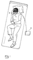
- the device has an optical unit 1, which is arranged on a, for example spectacle-frame-like, carrier 2 arranged in a fixed distance in front of the eyes of the user, so that the optical unit is arranged directly in front of one eye of the user. Leads run from the optical unit 1 to a central processing unit 3 located at an arbitrary, suitable place, which contains means for controlling different functions of the optical unit and to which further equipment is connectable.
- a central processing unit 3 located at an arbitrary, suitable place, which contains means for controlling different functions of the optical unit and to which further equipment is connectable.
- FIG. 1 the optical unit 1 arranged on the carrier and the central unit 3 each has been framed in by dashed lines.
- One of the eyes of the person is provided with the reference 4.
- a spectacle lens 5 is arranged in front of the eye 4 of the person for correcting possible visual defects.
- the eye 4 looks at the environment 6 through a first plane mirror 7 semitransparent to the visible light. The field of view is thereby restricted to 30° horizontally and vertically.
- Two light sources 8 emitting infrared light in this case in the form of a light emitting diode, the emitted light of which is led by a thin light fibre bundle to a small prism which finally reflects towards the eye, are arranged beside the eye 4 of the person to illuminate the eye 4 obliquely from the sides so as to achieve a good contrast between the dark pupil and the surrounding iris on the image of the eye thrown upon the first plane mirror 7.
- a system of lenses 9 acting as a convex lens is arranged along an optical axis extending through the rotational centre of the eye and in reflexion by the plane mirror 7 in such a way, that the pupil of the eye lies substantially in the focal plane of the system of lenses, which means that light beams emitted from one point of the pupil of the eye and reflected by the first plane mirror 7 towards the system of lenses 9 will be refracted by the system of lenses 9, so that they leave this in the form of parallel light beams.
- the first plane mirror 7 is preferably high-reflecting just for infrared light.
- a second plane mirror 10 also semitransparent to visible light and high-reflecting to infrared radiation is arranged along the optical axis passing through the system of lenses 9.
- the light beams emanating from the eye 4 and refracted by the system of lenses 9 are reflected by the second plane mirror 10 towards a third semitransparent plane mirror 11, through which the main part of the light beams pass, and through a band-pass filter 12, which is arranged to filter out the main part of the light not being in the wave-length field of the beams emanating from the light sources 8 - in this case about 880 nm.
- the parallel light beams emanating from the eye then arrive to the objective 13, in the form of a convex lens, of a video camera 14.
- the video camera 14 has a detector plane 15 located in the focal plane of the objective 13, on which the beams emanating from one point of the eye and made parallel by the system of lenses are refracted by the objective 13 together in one point.
- An image of the eye 4 is in this way created on the detector plane 15 and thanks to the light sources 8 there is a good contrast in this image between the dark pupil and the surrounding iris.
- the optical unit 1 also comprises a further light source 16 emitting infrared light of the same wave-length as the light sources 8.
- This light source 16 consists of a light emitting diode and is located in the focal plane of the system of lenses 9 and is directed so that the light emitted therefrom firstly will be reflected by the third plane mirror and then by the second plane mirror against the system of lenses 9 along the optical axis of the optical system. This means that the light beams emitted by the light source 16 will be refracted by the optical system of lenses into parallel light beams, which are reflected by the plane mirror 7 towards the cornea of the the eye.
- the cornea of the eye functions in such a way that it reflects a light beam inciding thereupon as if it came from a point on the half radius of curvature of the cornea, and by the fact that such a point lies in substantially the same plane as the pupil and thereby in the focal plane in the system of lenses 9 the light beams emanating from the light source 16 and reflected by the cornea of the eye will after repeated reflexion by the first plane mirror be refracted by the system of lenses 9 to parallel beams, which are reflected by the second plane mirror 10, pass through the third plane mirror 11 and the band-pass filter 12 and finally are refracted by the objective 13 into an image of the cornea reflex on the detector plane 15 of the video camera 14. It will be explained later on that the gaze direction of the eye may be determined from the pieces of information about the position of the cornea reflex and the pupil on the detector plane 15.
- a video monitor 17 is arranged in a fixed position on the carrier and with respect to the other optical elements just described.
- the video monitor 17 is arranged to show pictures with different symbols, which the person may hold his gaze at so as to communicate with the environment, control the video monitor or any machine or the like, to the eye 4 of the person.
- the video monitor 17 emits picture light passing through the second plane mirror 10 and the system of lenses 9 and is then reflected by the first plane mirror 7 towards the eye 4 of the person, so that a visible virtual picture 18 is obtained behind the plane mirror 7.
- the virtual picture 18 is located at a fixed distance with respect to the eye 4 of the person, but this distance may be variated by adjusting the display plane 19 of the video monitor 17.
- An electronic light limiter 20 is arranged behind the plane mirror 7 to regulate the extent of light from the environment 6.
- the electronic light limiter 20 may be controlled by the person by looking through the eye 4 at a suitable symbol on the virtual picture 18 displayed by the video monitor.
- the virtual picture is in reality of course located at a considerable distance in front of the optical unit, namely between 30 cm and at an indefinite sight distance therefrom.
- Picture signals emanating from the detector plane of the video camera 14 are led to a picture evaluating unit 21 included in the central processing unit 3 and arranged to evaluate these picture signals and from them and other information about the parameters in the optical system previously described calculate the gaze direction of the eye 4 of the person. Then the evaluating unit 21 sends information about at which point on the virtual picture the person is looking onto a fixation unit 22, which is arranged to determine whether the gaze direction of the user corresponds to any command, i.e. whether the gaze direction lies within or without the hit region centered around each fixation point. The fixation unit 22 also decides if the eye is completely still or roving and whether the user has fixed the gaze for a time long enough to make a command considered as selected.
- a command system 23 which in principle is a computer program package with different command procedures, which in the practice define what may be carried out with the product. Furthermore the carrying out of a command is indicated by immediate light signalization and/or by visual indication adjacent to the symbol in question on the virtual picture through a menu system 24.
- the command system 23 is arranged to send control signals to the menu system 24, which in its turn controls the video monitor 17 to display different menus to the eye 4 of the person. Furthermore, the command system 23 is also adapted to send control parameters to the fixation unit 22.
- the electronic light limiter 20 may also be controlled through the command system 23.
- the command system 23 also contains the routines 25, which enable two-way communication with equipments 26, which are connected to the central processing unit 3.
- the equipments 26 may comprise a pointing-out screen, an alarm and calling apparatus, optional accessories and the like.
- the purpose of the device according to the invention is to determine accurately towards which point on the virtual picture 18 the gaze of the eye 4 of the person is directed also when the carrier 2, i.e. the optical unit 1, is slightly laterally displaced with respect to the eye 4 of the person.
- the carrier 2 i.e. the optical unit 1
- the eye 4 When the user is studying a fixation point on the virtual picture the eye 4 is turned by an angle A with respect to the optical axis. In order to decide on which of the fixation points of the virtual picture the eye is fixed to, the angle of rotation A of the eye must be determined. It will now be explained how this may be achieved in an accurate manner despite a lateral displacement of the optical unit with respect to the eye.
- the parallel light emanating from the light source 16 and inciding towards the eye is partially reflected by the cornea of the eye, which acts as a convex, spherical mirror with the radius of curvature r.
- the beam intersecting the centre of the cornea globus is reflected directly in the opposite direction, while the other beams are reflected in varying directions, and for small angles it is true that they are reflected as if they came from a point at a distance r/2 from the front edge of the cornea.
- Such points at the distance r/2 from the front edge of the cornea lie in substantially the same plane being perpendicular to the optical axis of the optical system and coinciding with the focal plane of the system of lenses 9.
- the pupil pu is located at the distance q from the rotation centre of the eye (see Fig 5).
- the evaluating unit 21 calculates by means of this equation the angle A and thus the distortion of the eye.
- the detector used has the following data.
- the invention is based on the understanding that information may be obtained from an image of the eye being in a connection, which is independent of a lateral displacement of the optical unit with respect to the eye, and that these pieces of information may be used to calculate the distortion or angle of the eye, so that the result of such a calculation is independent of possible lateral displacements of said kind.
- information may be obtained from an image of the eye being in a connection, which is independent of a lateral displacement of the optical unit with respect to the eye, and that these pieces of information may be used to calculate the distortion or angle of the eye, so that the result of such a calculation is independent of possible lateral displacements of said kind.
- the particular properties of the cornea of the eye and particular arrangement of different components of the optical system with respect to each other and with respect to the eye are used, so that light emitted, or more accurate reflected, by the cornea as well as by the pupil will substantially emanate from the focal plane of the system of lenses.
- a contact lens provided with a mark may for instance be placed on the eye of the person and the position of this mark in the detector plane could be used instead of the position of the pupil.
Landscapes
- Engineering & Computer Science (AREA)
- Theoretical Computer Science (AREA)
- General Engineering & Computer Science (AREA)
- Human Computer Interaction (AREA)
- Health & Medical Sciences (AREA)
- Life Sciences & Earth Sciences (AREA)
- Veterinary Medicine (AREA)
- Biomedical Technology (AREA)
- Heart & Thoracic Surgery (AREA)
- Vascular Medicine (AREA)
- Physics & Mathematics (AREA)
- Animal Behavior & Ethology (AREA)
- General Health & Medical Sciences (AREA)
- Public Health (AREA)
- General Physics & Mathematics (AREA)
- Eye Examination Apparatus (AREA)
- Input Circuits Of Receivers And Coupling Of Receivers And Audio Equipment (AREA)
- Optical Communication System (AREA)
- Prostheses (AREA)
- Position Input By Displaying (AREA)
- Superconductors And Manufacturing Methods Therefor (AREA)
- Measuring Pulse, Heart Rate, Blood Pressure Or Blood Flow (AREA)
- Devices For Checking Fares Or Tickets At Control Points (AREA)
Claims (11)
- Vorrichtung, die es ermöglicht besonders behinderten Personen, ohne die Fähigkeit zu sprechen oder ihre Arme zu bewegen, mit ihrer Umgebung zu kommunizieren, die umfaßt: eine Einrichtung (7-15), die geeignet ist, die Blickrichtung eines der Augen (4) dieser Person zu erfassen, eine Einheit (21), die geeignet ist, die Richtungsinformation dieser Einrichtung auszuwerten und ein Signal abzugeben, dessen Eigenschaften von der Blickrichtung dieser Person abhängen, eine Vorrichtung (17, 24), die eingerichtet ist, der Person eines oder mehrere Bilder zu zeigen und die ein bildaussendendes Element (17) aufweist, wobei diese Bilder mit Symbolen oder Text versehen sind, die unterschiedlichen Informationen entsprechen, von denen angenommen wird, daß die Person sie beispielsweise einer anderen Person oder einer Maschine mitteilen will, wobei diese Auswerteeinheit geeignet ist zu ermitteln, worauf in diesem Bild die Person ihre Blickrichtung gerichtet hat, und wobei diese Erfassungseinrichtung ein lichtempfindliches Element (14) aufweist, auf das das von einem Auge dieser Person reflektierte Licht direkt oder indirekt fallen soll, wobei diese Erfassungseinrichtung außerdem ein optisches System (7, 9-11) umfaßt, das nahe vor einem der Augen dieser Person in einer festen Position bezüglich dieses Auges angeordnet ist, wobei dieses System Spiegel (7, 10, 11) und/oder Linsen (9) umfaßt und geeignet ist, ein Bild des Auges dieser Person direkt auf dieses lichtempfindliche Element zu werfen, wobei diese Auswerteeinheit angeordnet ist, um die Blickrichtung dieses Auges der Person aus Information von dem auf das lichtempfindliche Element geworfenen Bild des Auges zu errechnen, wobei diese Einrichtung einen Träger (2) umfaßt, etwa in Form eines Elements ähnlich einem Brillenrahmen, und wenigstens das bildaussendende Element (17) der Vorrichtung und das optische System der Erfassungseinrichtung und auch das lichtempfindliche Element auf diesem Träger in gegenseitigem festen Abstand angeordnet sind, wobei beabsichtigt ist, den Träger nahe vor den Augen dieser Person in einer vorher festgelegten Position relativ zu dem zu untersuchenden Auge anzubringen, dadurch gekennzeichnet, daß die Auswerteeinheit (21) eine Einrichtung umfaßt, um aus der Bildinformation, die aus dem von dem Auge der Person auf das lichtempfindliche Element (14, 15) ausgesandten Licht hervorgeht, zwei unterschiedliche Parameter der Bildinformation von dem Auge der Person auszuwählen, die einen gegenseitigen Abstand auf dem lichtempfindlichen Element aufweisen, der eine Funktion des Winkels (A) ist, der zwischen der Blickrichtung des Auges und der optischen Achse des Systems gebildet wird und unabhängig ist von kleinen seitlichen Abweichungen zwischen dem Träger und dem Auge der Person, und die Auswerteeinheit (21) eine Einrichtung zum Errechnen dieses Winkels und damit zur Blickrichtung der Person aus diesen Parametern der Bildinformation aufweist.
- Vorrichtung nach Anspruch 1, dadurch gekennzeichnet, daß einer dieser Parameter der Bildinformation ein Lichtreflex von der Hornhaut des Auges ist und der anderer dieser Parameter der Bildinformation das Bild eines Punktes ist, der dem Auge bei dessen Bewegung folgt.
- Vorrichtung nach Anspruch 2, dadurch gekennzeichnet, daß der dem Auge folgende Punkt die Pupillenöffnung (pu) des Auges ist.
- Vorrichtung nach Anspruch 2 oder 3, dadurch gekennzeichnet, daß das optische System ein System (9) von einer oder mehreren Linsen umfaßt, die sich wie eine konvexe Linse verhalten, daß diese Einrichtung eine Lichtquelle (16) umfaßt, die im Brennpunkt dieses Linsensystems auf einer ersten Seite davon angeordnet ist und daß das optische System geeignet ist, die parallelen Lichtstrahlen, die von der Lichtquelle ausgehen und auf der anderen Seite des Linsensystems austreten, auf das Auge der Person zu werfen.
- Vorrichtung nach Anspruch 4, dadurch gekennzeichnet, daß das Linsensystem (9) so auf dem Träger angeordnet ist, daß die Mitte des Hornhautbereichs des Auges (4) in einem Abstand von im wesentlichen des halben Krümmungsradius' der Hornhaut hinter der Brennebene des Linsensystems auf dieser zweiten Seite angeordnet ist, so daß die parallelen Lichtstrahlen der Lichtquelle, die auf das Auge fallen und von der Hornhaut reflektiert werden, als ob sie von einem Punkt auf der Hälfte des Krümmungsradius' der Hornhaut kämen, von dem Linsensystem (9) erneut gebrochen werden, so daß sie parallel zueinander verlaufen, wenn sie auf der ersten Seite austreten.
- Vorrichtung nach Anspruch 5, dadurch gekennzeichnet, daß das lichtempfindliche Element eine Kamera (14) umfaßt und daß das Objektiv (13) der Kamera auf dieser ersten Seite des Linsensystems angebracht ist, wobei sein optischer Mittelpunkt auf der optischen Achse des Linsensystems liegt, so daß die parallelen Lichtstrahlen, die von der Reflektion auf der Hornhaut herrühren, gebrochen werden auf einen Punkt in der Fokussierebene des Kameraobjektivs.
- Vorrichtung nach einem der Ansprüch 4-6, dadurch gekennzeichnet, daß das bildaussendende Element (17) der Vorrichtung längs der optischen Achse des Linsensystems auf dessen erster Seite angebracht ist und daß das bildaussendende Element so angeordnet ist, daß es ein Bild zeigt, indem es dieses durch das Linsensystem (9) längs dessen optischer Achse aussendet.
- Vorrichtung nach Anspruch 5, dadurch gekennzeichnet, daß das optische System einen ersten planen Spiegel (7) umfaßt, der in einer festgelegten Position vor dem Auge (4) der Person angebracht werden soll, und daß der Spiegel so angeordnet ist, um durch andere im optischen System enthaltene Elemente ein virtuelles, von der Vorrichtung hinter dem ersten planen Spiegel gezeigtes Bild zu erzeugen.
- Vorrichtung nach den Ansprüchen 4 und 8, dadurch gekennzeichnet, daß dieser erste plane Spiegel (7) angeordnet ist, um Lichtstrahlen, die von dem Linsensystem (9) kommen, in Richtung des Auges (4) der Person zu reflektieren und Lichtstrahlen, die vom Auge der Person reflektiert werden, in Richtung des Linsensystems zu reflektieren.
- Vorrichtung nach Anspruch 9, dadurch gekennzeichnet, daß das optische System einen zweiten planen Spiegel (10) umfaßt, der angeordnet ist, um Lichtstrahlen, die von dem Linsensystem gebrochen sind und von dem Auge in Richtung des lichtempfindlichen Elements ausgehen, zu reflektieren, und daß dieser plane Spiegel halbdurchlässig ist und angeordnet ist in dem Pfad, den das Bild von dem bildaussendenden Element in Richtung des Linsensystems nimmt.
- Vorrichtung nach Anspruch 10, dadurch gekennzeichnet, daß das optische System einen dritten planen Spiegel (11) umfaßt, der zwischen dem zweiten planen Spiegel (10) und dem lichtempfindlichen Element (14, 15) angeordnet ist, daß dieser plane Spiegel halbdurchlässig ist, um Lichtstrahlen, die von dem zweiten planen Spiegel in Richtung des lichtempfindlichen Elements reflekltiert werden, passieren zu lassen, und daß dieser dritte plane Spiegel so angeordnet ist, um Licht, das von der Lichtquelle (16) in Richtung des zweiten planen Spiegels (10) ausgesandt wird, zu reflektieren, so daß es hierdurch in Richtung des Linsensystems (9) reflektiert wird.
Applications Claiming Priority (3)
| Application Number | Priority Date | Filing Date | Title |
|---|---|---|---|
| SE8903713 | 1989-11-07 | ||
| SE8903713A SE464910B (sv) | 1989-11-07 | 1989-11-07 | Anordning foer moejliggoerande foer i synnerhet handikappade personer utan talfoermaaga och roerelsefoermaaga i armarna att kommunicera med omgivningen |
| PCT/SE1990/000718 WO1991006263A1 (en) | 1989-11-07 | 1990-11-06 | A communication device |
Publications (2)
| Publication Number | Publication Date |
|---|---|
| EP0500672A1 EP0500672A1 (de) | 1992-09-02 |
| EP0500672B1 true EP0500672B1 (de) | 1995-08-09 |
Family
ID=20377394
Family Applications (1)
| Application Number | Title | Priority Date | Filing Date |
|---|---|---|---|
| EP90916833A Expired - Lifetime EP0500672B1 (de) | 1989-11-07 | 1990-11-06 | Kommunikationsvorrichtung |
Country Status (7)
| Country | Link |
|---|---|
| EP (1) | EP0500672B1 (de) |
| JP (1) | JP3215415B2 (de) |
| AT (1) | ATE126044T1 (de) |
| AU (1) | AU6730790A (de) |
| DE (1) | DE69021581T2 (de) |
| SE (1) | SE464910B (de) |
| WO (1) | WO1991006263A1 (de) |
Families Citing this family (6)
| Publication number | Priority date | Publication date | Assignee | Title |
|---|---|---|---|---|
| GB2308212A (en) * | 1995-12-15 | 1997-06-18 | Christopher Wright | Visual keyboard communicator |
| DE19731301C2 (de) * | 1997-07-13 | 2001-05-10 | Smi Senso Motoric Instr Gmbh | Vorrichtung zum Steuern eines Mikroskopes mittels Blickrichtungsanalyse |
| US6426740B1 (en) | 1997-08-27 | 2002-07-30 | Canon Kabushiki Kaisha | Visual-axis entry transmission apparatus and method therefor |
| DE19812899C2 (de) * | 1997-12-18 | 2001-03-15 | Klaus Schultze | Vorrichtung und Verfahren zur Objektbildnachführung |
| FR2775588B1 (fr) * | 1998-03-03 | 2000-08-11 | Jacques Patrick Andres | Systeme permettant a des personnes handicapees de communiquer avec leur environnement en utilisant le mouvement de leurs yeux et paupieres |
| NO994445D0 (no) | 1999-09-13 | 1999-09-13 | Bjoern Franc Iversen | FremgangsmÕte samt verktöy for kontroll av innbyrdes vinkel mellom delene i hofteleddsprotese |
Family Cites Families (2)
| Publication number | Priority date | Publication date | Assignee | Title |
|---|---|---|---|---|
| WO1986001963A1 (en) * | 1984-09-24 | 1986-03-27 | The University Of Adelaide | Improvements relating to an apparatus and method related to control through eye gaze direction |
| SE453959B (sv) * | 1986-06-04 | 1988-03-21 | Gote Palsgard | Anordning for mojliggorande for i synnerhet handikappade personer utan talformaga och rorelseformaga i armarna att kommunicera med omgivningen |
-
1989
- 1989-11-07 SE SE8903713A patent/SE464910B/sv not_active IP Right Cessation
-
1990
- 1990-11-06 AT AT90916833T patent/ATE126044T1/de not_active IP Right Cessation
- 1990-11-06 JP JP51547390A patent/JP3215415B2/ja not_active Expired - Fee Related
- 1990-11-06 EP EP90916833A patent/EP0500672B1/de not_active Expired - Lifetime
- 1990-11-06 DE DE69021581T patent/DE69021581T2/de not_active Expired - Fee Related
- 1990-11-06 WO PCT/SE1990/000718 patent/WO1991006263A1/en not_active Ceased
- 1990-11-06 AU AU67307/90A patent/AU6730790A/en not_active Abandoned
Also Published As
| Publication number | Publication date |
|---|---|
| EP0500672A1 (de) | 1992-09-02 |
| JPH05501822A (ja) | 1993-04-08 |
| AU6730790A (en) | 1991-05-31 |
| ATE126044T1 (de) | 1995-08-15 |
| SE8903713L (sv) | 1991-05-08 |
| JP3215415B2 (ja) | 2001-10-09 |
| SE8903713D0 (sv) | 1989-11-07 |
| WO1991006263A1 (en) | 1991-05-16 |
| SE464910B (sv) | 1991-07-01 |
| DE69021581D1 (de) | 1995-09-14 |
| DE69021581T2 (de) | 1996-04-25 |
Similar Documents
| Publication | Publication Date | Title |
|---|---|---|
| US5225862A (en) | Visual axis detector using plural reflected image of a light source | |
| EP1131663B1 (de) | System für die blickrichtung der augen | |
| US6580448B1 (en) | Process and device for the parallel capture of visual information | |
| EP2503932B1 (de) | Augenverfolgung | |
| EP1700562B1 (de) | Vorrichtung zur Messung von Augenpunkten eines Subjektes im Bezug auf ein Brillengestell | |
| FI125445B (fi) | Katseenohjausjärjestely | |
| US7298414B2 (en) | Digital camera autofocus using eye focus measurement | |
| JP3445635B2 (ja) | 眼科装置 | |
| JPH0824358B2 (ja) | 画像ディスプレー装置 | |
| EP1088511A1 (de) | Augenuntersuchungsgerät | |
| KR20230003654A (ko) | 다중-레이어 뷰잉 시스템 및 방법 | |
| JP2006308674A (ja) | 画像表示装置 | |
| JP4616303B2 (ja) | 眼位置測定装置 | |
| US5767821A (en) | Communication device | |
| JP2004033744A (ja) | 携帯型の眼科装置用の調整システム | |
| EP0500672B1 (de) | Kommunikationsvorrichtung | |
| US4175861A (en) | System for the alignment of a laser beam transmitter with a sighting mechanism set up in another place | |
| JPH08286141A (ja) | 注視点検出システム及びそれを用いた制御システム | |
| EP0177005A2 (de) | Augenuntersuchungsgerät | |
| JPH11197108A (ja) | 視機能検査装置 | |
| JP2550128B2 (ja) | 視線方向検出方法 | |
| JP2507913B2 (ja) | 投射方式による眼球運動追従型視覚提示装置 | |
| KR20020073655A (ko) | 홍채 인식 시스템의 촛점 각도 표시장치 | |
| JPH0315438A (ja) | 眼科機器のアライメント装置 | |
| JP2995878B2 (ja) | 視線検出装置を有した光学装置 |
Legal Events
| Date | Code | Title | Description |
|---|---|---|---|
| PUAI | Public reference made under article 153(3) epc to a published international application that has entered the european phase |
Free format text: ORIGINAL CODE: 0009012 |
|
| 17P | Request for examination filed |
Effective date: 19920514 |
|
| AK | Designated contracting states |
Kind code of ref document: A1 Designated state(s): AT BE CH DE DK ES FR GB IT LI LU NL SE |
|
| 17Q | First examination report despatched |
Effective date: 19931119 |
|
| GRAA | (expected) grant |
Free format text: ORIGINAL CODE: 0009210 |
|
| AK | Designated contracting states |
Kind code of ref document: B1 Designated state(s): AT BE CH DE DK ES FR GB IT LI LU NL SE |
|
| PG25 | Lapsed in a contracting state [announced via postgrant information from national office to epo] |
Ref country code: IT Free format text: LAPSE BECAUSE OF FAILURE TO SUBMIT A TRANSLATION OF THE DESCRIPTION OR TO PAY THE FEE WITHIN THE PRE;WARNING: LAPSES OF ITALIAN PATENTS WITH EFFECTIVE DATE BEFORE 2007 MAY HAVE OCCURRED AT ANY TIME BEFORE 2007. THE CORRECT EFFECTIVE DATE MAY BE DIFFERENT FROM THE ONE RECORDED.SCRIBED TIME-LIMIT Effective date: 19950809 Ref country code: BE Effective date: 19950809 Ref country code: ES Free format text: THE PATENT HAS BEEN ANNULLED BY A DECISION OF A NATIONAL AUTHORITY Effective date: 19950809 Ref country code: DK Effective date: 19950809 Ref country code: NL Free format text: LAPSE BECAUSE OF NON-PAYMENT OF DUE FEES Effective date: 19950809 Ref country code: AT Effective date: 19950809 |
|
| REF | Corresponds to: |
Ref document number: 126044 Country of ref document: AT Date of ref document: 19950815 Kind code of ref document: T |
|
| REF | Corresponds to: |
Ref document number: 69021581 Country of ref document: DE Date of ref document: 19950914 |
|
| PG25 | Lapsed in a contracting state [announced via postgrant information from national office to epo] |
Ref country code: SE Effective date: 19951109 |
|
| PG25 | Lapsed in a contracting state [announced via postgrant information from national office to epo] |
Ref country code: LU Free format text: LAPSE BECAUSE OF NON-PAYMENT OF DUE FEES Effective date: 19951130 |
|
| PGFP | Annual fee paid to national office [announced via postgrant information from national office to epo] |
Ref country code: CH Payment date: 19951130 Year of fee payment: 6 |
|
| ET | Fr: translation filed | ||
| NLV1 | Nl: lapsed or annulled due to failure to fulfill the requirements of art. 29p and 29m of the patents act | ||
| PLAV | Examination of admissibility of opposition |
Free format text: ORIGINAL CODE: EPIDOS OPEX |
|
| PLBQ | Unpublished change to opponent data |
Free format text: ORIGINAL CODE: EPIDOS OPPO |
|
| PLBI | Opposition filed |
Free format text: ORIGINAL CODE: 0009260 |
|
| PLAV | Examination of admissibility of opposition |
Free format text: ORIGINAL CODE: EPIDOS OPEX |
|
| PLBF | Reply of patent proprietor to notice(s) of opposition |
Free format text: ORIGINAL CODE: EPIDOS OBSO |
|
| 26 | Opposition filed |
Opponent name: CANON KABUSHIKI KAISHA Effective date: 19960509 |
|
| PG25 | Lapsed in a contracting state [announced via postgrant information from national office to epo] |
Ref country code: CH Free format text: LAPSE BECAUSE OF FAILURE TO SUBMIT A TRANSLATION OF THE DESCRIPTION OR TO PAY THE FEE WITHIN THE PRESCRIBED TIME-LIMIT Effective date: 19961130 Ref country code: LI Free format text: LAPSE BECAUSE OF FAILURE TO SUBMIT A TRANSLATION OF THE DESCRIPTION OR TO PAY THE FEE WITHIN THE PRESCRIBED TIME-LIMIT Effective date: 19961130 |
|
| PLBF | Reply of patent proprietor to notice(s) of opposition |
Free format text: ORIGINAL CODE: EPIDOS OBSO |
|
| PLBF | Reply of patent proprietor to notice(s) of opposition |
Free format text: ORIGINAL CODE: EPIDOS OBSO |
|
| PLBF | Reply of patent proprietor to notice(s) of opposition |
Free format text: ORIGINAL CODE: EPIDOS OBSO |
|
| PLBL | Opposition procedure terminated |
Free format text: ORIGINAL CODE: EPIDOS OPPC |
|
| PLBM | Termination of opposition procedure: date of legal effect published |
Free format text: ORIGINAL CODE: 0009276 |
|
| STAA | Information on the status of an ep patent application or granted ep patent |
Free format text: STATUS: OPPOSITION PROCEDURE CLOSED |
|
| 27C | Opposition proceedings terminated |
Effective date: 19970803 |
|
| REG | Reference to a national code |
Ref country code: GB Ref legal event code: IF02 |
|
| PGFP | Annual fee paid to national office [announced via postgrant information from national office to epo] |
Ref country code: FR Payment date: 20021129 Year of fee payment: 13 |
|
| PGFP | Annual fee paid to national office [announced via postgrant information from national office to epo] |
Ref country code: DE Payment date: 20021217 Year of fee payment: 13 |
|
| PGFP | Annual fee paid to national office [announced via postgrant information from national office to epo] |
Ref country code: GB Payment date: 20030430 Year of fee payment: 13 |
|
| PG25 | Lapsed in a contracting state [announced via postgrant information from national office to epo] |
Ref country code: GB Free format text: LAPSE BECAUSE OF NON-PAYMENT OF DUE FEES Effective date: 20031106 |
|
| PG25 | Lapsed in a contracting state [announced via postgrant information from national office to epo] |
Ref country code: DE Free format text: LAPSE BECAUSE OF NON-PAYMENT OF DUE FEES Effective date: 20040602 |
|
| GBPC | Gb: european patent ceased through non-payment of renewal fee |
Effective date: 20031106 |
|
| PG25 | Lapsed in a contracting state [announced via postgrant information from national office to epo] |
Ref country code: FR Free format text: LAPSE BECAUSE OF NON-PAYMENT OF DUE FEES Effective date: 20040730 |
|
| REG | Reference to a national code |
Ref country code: FR Ref legal event code: ST |