EP0500912B1 - Baggerzahnspitze mit elastischer verriegelung - Google Patents
Baggerzahnspitze mit elastischer verriegelung Download PDFInfo
- Publication number
- EP0500912B1 EP0500912B1 EP91917505A EP91917505A EP0500912B1 EP 0500912 B1 EP0500912 B1 EP 0500912B1 EP 91917505 A EP91917505 A EP 91917505A EP 91917505 A EP91917505 A EP 91917505A EP 0500912 B1 EP0500912 B1 EP 0500912B1
- Authority
- EP
- European Patent Office
- Prior art keywords
- point
- wall
- lock
- pin
- cavity
- Prior art date
- Legal status (The legal status is an assumption and is not a legal conclusion. Google has not performed a legal analysis and makes no representation as to the accuracy of the status listed.)
- Expired - Lifetime
Links
- 230000001154 acute effect Effects 0.000 claims 1
- 230000037431 insertion Effects 0.000 claims 1
- 238000003780 insertion Methods 0.000 claims 1
- 239000013598 vector Substances 0.000 description 5
- 230000014759 maintenance of location Effects 0.000 description 4
- 238000009434 installation Methods 0.000 description 3
- XEEYBQQBJWHFJM-UHFFFAOYSA-N Iron Chemical compound [Fe] XEEYBQQBJWHFJM-UHFFFAOYSA-N 0.000 description 2
- 238000010276 construction Methods 0.000 description 2
- 238000010586 diagram Methods 0.000 description 2
- 229920001971 elastomer Polymers 0.000 description 2
- 239000000806 elastomer Substances 0.000 description 2
- 229920005830 Polyurethane Foam Polymers 0.000 description 1
- 239000013536 elastomeric material Substances 0.000 description 1
- 229910052742 iron Inorganic materials 0.000 description 1
- 230000013011 mating Effects 0.000 description 1
- 239000002184 metal Substances 0.000 description 1
- 229910052751 metal Inorganic materials 0.000 description 1
- 238000000034 method Methods 0.000 description 1
- 230000004048 modification Effects 0.000 description 1
- 238000012986 modification Methods 0.000 description 1
- 230000000149 penetrating effect Effects 0.000 description 1
- 239000011496 polyurethane foam Substances 0.000 description 1
- 238000009420 retrofitting Methods 0.000 description 1
- 230000002441 reversible effect Effects 0.000 description 1
Images


Classifications
-
- E—FIXED CONSTRUCTIONS
- E02—HYDRAULIC ENGINEERING; FOUNDATIONS; SOIL SHIFTING
- E02F—DREDGING; SOIL-SHIFTING
- E02F9/00—Component parts of dredgers or soil-shifting machines, not restricted to one of the kinds covered by groups E02F3/00 - E02F7/00
- E02F9/28—Small metalwork for digging elements, e.g. teeth scraper bits
- E02F9/2808—Teeth
- E02F9/2816—Mountings therefor
- E02F9/2833—Retaining means, e.g. pins
- E02F9/2841—Retaining means, e.g. pins resilient
-
- Y—GENERAL TAGGING OF NEW TECHNOLOGICAL DEVELOPMENTS; GENERAL TAGGING OF CROSS-SECTIONAL TECHNOLOGIES SPANNING OVER SEVERAL SECTIONS OF THE IPC; TECHNICAL SUBJECTS COVERED BY FORMER USPC CROSS-REFERENCE ART COLLECTIONS [XRACs] AND DIGESTS
- Y10—TECHNICAL SUBJECTS COVERED BY FORMER USPC
- Y10T—TECHNICAL SUBJECTS COVERED BY FORMER US CLASSIFICATION
- Y10T403/00—Joints and connections
- Y10T403/70—Interfitted members
- Y10T403/7075—Interfitted members including discrete retainer
- Y10T403/7077—Interfitted members including discrete retainer for telescoping members
- Y10T403/7079—Transverse pin
- Y10T403/7086—Wedge pin
Definitions
- This invention relates to an excavating tooth point and, more particularly, one advantageously employed on large dragline buckets where the teeth are of substantial size.
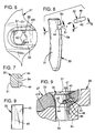
- FIG. 1 represents the prior art as seen in Patent 4,326,348, the numeral 20 designates generally an adapter while the numeral 21 generally designates a tooth point having a forward end earth engaging edge 22.
- the adapter 20 is protected by wear caps 23 and 24.
- the point 21 is secured to the adapter 20 by means of side pins as at 25 which are equipped with snap rings as at 26.
- a tooth point generally designated 27 is mounted on the nose 28 of an adapter generally designated 29.
- the point and adapter nose are releasably secured together by locking means generally designated 30 which include a vertically extending pin 31 (see also FIG. 6) and a lock generally designated 32.
- the point 27 is equipped with a top wall 33 and a bottom wall 34 which terminate forwardly in an earth-engaging edge 22 and at the rear end 22a cooperate with sidewalls as at 35 in defining a socket 36 for the receipt of the adapter nose 28.
- top and bottom walls 33, 34 are equipped with vertically aligned pin receiving openings as at 37 and 38 respectively.
- the nose 28 is equipped with an alignable opening 39 for the receipt of the locking pin 31.
- the top wall 33 of the point has an outside surface 41a and an inner surface 41b.
- the latter in part, defines the socket 36.
- a boss 42 which, as can be readily appreciated from FIG. 4, is located on both sides of the vertical-longitudinal midplane 43. It is in the pocket 40 within the boss 42 that the lock 32 is positioned and the lock 32 extends forwardly outwardly of the pocket 40 to engage a slot 44 in the pin 31 --see FIG. 6.
- the lock 32 features a dowel 45 (compare FIGS. 6 and 8) which is essentially cylindrical with the remainder of the lock being constructed of elastomeric material (polyurethane foam) which encases and backs the dowel 45 as at 46. Under certain circumstances, a spring may also be used to advantage with the elastomer to back the dowel 45.
- the circular cross-sectional shape of the dowel 45 is advantageous although other geometric shapes could be used.
- the lock cavity or pocket 40 is located so that the lock dowel 45 is aligned with the lock retention slot or notch 44 in the pin 31. Further, the cavity 40 is equipped with opposing surfaces as at 47 and 48 (see the right hand side of FIG. 4) which support both ends of the lock 32.
- the opposing wall surfaces 47, 48 are connected at their rear ends by a transverse wall surface 40c which is generally parallel to the rear wall surface 41c of the opening 37 and perpendicular to the side walls 35 (see FIGS. 3-5).
- the opposing surfaces 47, 48 are arranged in such a way that they act in conjunction with the lock retention slot to pinch or hold the dowel 45 in place when the pin 31 attempts to move up or down. This positively prevents undesirable pin ejection during service.
- the lock elastomer 46 also assists in holding the dowel 45 in place.
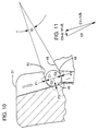
- the arrangement shown has an approximately 10 degree pinching or holding angle 0 (see FIG. 10) between the lock retention slot surface 50 and the cavity surface 48 and which provide an interference 49. Conversely, when the pin attempts to eject upwardly, the pinching or holding angle 0 is between the lock retention surface 51 and the cavity surface 47.
- FIG. 10 shows a diagram of the forces acting on the dowel 45 when the pin 31 attempts to move downwardly.
- the downward force vector P1 exerted by the pin 31 is opposed by the force vectors P2 and P3.
- P2 is exerted by the point surfaces 48 and P3 by the pin 31.
- FIG. 10 also shows the reaction forces in the dowel 45 itself, being respectively C1, C2 and C3 -- each one being normal to the surface contacting the dowel 45.
- the interference 49 is based upon the fact that the point has parallel lower cavity surfaces 48 which are at an angle 0 with respect to the parallel surfaces 50 defining the upper extent of the slot 44. Both the force C3 and the interference 49 hold the dowel 45 in place. As just explained, this interference is caused by the angle between the pin slot upper surfaces and lock cavity bottom surfaces. Thus, this is the reason for calling this feature the "dowel pinching or holding angle" which advantageously may be of the order of about 5° to 10°, optimally about 10°.
- This same type of action occurs when the pin attempts to eject upwardly.
- the same dowel pinching or holding function can be alternatively achieved by using arcuate surfaces or small protrusions or other geometries to work in conjunction with other than circular dowel cross sectional shapes.
- FIGS. 12-14 A modified form of lock means can be seen in FIGS. 12-14 where the elements are the same except for the fact that the nose opening is enlarged to accommodate a spring collar as at 152. This is advantageous for retrofitting installations already in the field.
- the lock 32 is inserted into the lock cavity 40.
- the point 27 is mounted on the nose 28 and the openings 37-39 aligned.
- the pin 31 is inserted into the top opening 37 and driven downward to compress the dowel pin 45 back into the lock cavity 40 until the dowel 45 snaps into the lock slot 44.
- FIGS. 15 and 16 Disassembly is illustrated in FIGS. 15 and 16 wherein a tool 53 (which also may be a screwdriver, small crowbar or sharp end of a tire iron), is inserted into aligned recesses 54, 55 in pin 31 and top wall 33, respectively - compare FIGS. 5 and 7, also FIGS. 15 and 16. As appropriate, either pry or wedge the dowel 45 back into the plug cavity 40 and then drive the pin 31 down and out as illustrated in FIGS. 15 and 16. An earlier version of this removal technique can be seen in my Patent 4,271,615.
- a tool 53 which also may be a screwdriver, small crowbar or sharp end of a tire iron
- the invention also accommodates rotation of the point, i.e., reversing the same to position the former bottom side uppermost.
- a second cavity 40' may be provided in the lower wall 34.
- the point 27 is symmetrical about the horizontal mid-plane 56 (see FIG. 16) but with non-reversible constructions, this is omitted.
- the size of the cavity 40 is readily controlled so that the advantageous pinching action referred to occurs predictably which is not always the case with a lock in positioned in a worn adapter.
- the lock by virtue of mounting the lock within the point rather than the worn adapter, a reproducible result in operation is obtained.
- the manufacturer's designed fit of the point and the locking system is employed new -- thus doing as much as possible to provide the strongest possible two-part tooth.
Landscapes
- Engineering & Computer Science (AREA)
- Mining & Mineral Resources (AREA)
- Civil Engineering (AREA)
- General Engineering & Computer Science (AREA)
- Structural Engineering (AREA)
- Component Parts Of Construction Machinery (AREA)
- Table Equipment (AREA)
- Shovels (AREA)
- Dental Tools And Instruments Or Auxiliary Dental Instruments (AREA)
- Devices For Conveying Motion By Means Of Endless Flexible Members (AREA)
- Snaps, Bayonet Connections, Set Pins, And Snap Rings (AREA)
- Purses, Travelling Bags, Baskets, Or Suitcases (AREA)
- Mechanical Pencils And Projecting And Retracting Systems Therefor, And Multi-System Writing Instruments (AREA)
- Gears, Cams (AREA)
- Earth Drilling (AREA)
- Respiratory Apparatuses And Protective Means (AREA)
- Orthopedics, Nursing, And Contraception (AREA)
- Dowels (AREA)
- Fluid-Damping Devices (AREA)
- Artificial Filaments (AREA)
- Massaging Devices (AREA)
- Manufacture Of Alloys Or Alloy Compounds (AREA)
- Materials For Medical Uses (AREA)
Claims (10)
- Zahnspitze mit einem verhältnismäßig langgestreckten unitären Körper (27) mit einer Erdeingriffskante (22) an dem vorderen Ende und mit einer Muffe (36), die sich von dem hinteren Ende (22a) des Körpers nach vorne erstreckt, wobei die Spitze (27) durch eine Oberseite (33), eine Unterseite (34) und ein Seitenwandpaar (35) begrenzt ist, und wobei ausgerichtete Bolzenaufnahmeöffnungen (37, 38) in der oberen und der unteren Wand (34, 35) ausgebildet sind, die vor dem hinteren Ende mit Abstand angeordnet sind und in Verbindung mit der Muffe (36) stehen, wobei die Oberseite (33) in der Nachbarschaft der Öffnung (37) in der Oberseite eine obere Oberfläche (41a) vorsieht, die einen Teil des Äußeren der Spitze bildet, und wobei eine untere Oberfläche (41b) einen Teil der Muffe vorsieht, wobei die genannte Oberseitenöffnung (37) eine allgemein vertikale Oberfläche (41c) vorsieht, welche die obere und die untere Oberfläche (41a, 41b) verbindet, dadurch gekennzeichnet, daß die allgemein vertikale Oberfläche (41c) mit einer Vertiefung (40) zur Aufnahme einer Verriegelungseinrichtung (32) versehen ist, die mit einem Bolzen (31) in den Öffnungen der Spitze eingreifen kann, wobei die Vertiefung obere und untere Seiten (47, 48) aufweist, die sich allgemein senkrecht zu den Seitenwänden (35) erstrecken, wodurch die oberen und unteren Seiten (47, 48) eine Verriegelungseinrichtung (32) vor dem Eingriff mit einem Bolzen (31) in den Öffnungen (37, 38) alleine stützen können.
- Spitze nach Anspruch 1, wobei sich die oberen und unteren Seiten (47, 48) der Vertiefung allgemein parallel zu den oberen und unteren Oberflächen (41a, 41b) erstrecken.
- Spitze nach Anspruch 1, wobei die Spitze um die sich der Länge nach erstreckende horizontale Mittelebene (56) des Zahns allgemein symmetrisch ist, wobei die Unterseite (34) ebenfalls mit einer Vertiefung (40') versehen ist, die von der Öffnung (38) in der Unterseite vorsteht.
- Spitze nach Anspruch 1, wobei die Oberseite (33) einen integralen runden Vorsprung (42) aufweist, der von der unteren Oberfläche (41b) symmetrisch um eine sich längs erstreckende vertikale Mittelebene (43) abhängig ist, wobei sich die Vertiefung (40) in dem runden Vorsprung (43) befindet.
- Spitze nach Anspruch 1, wobei die allgemein vertikale Oberfläche an der sich längs erstreckenden vertikalen Mittelebene (43) eine Rille (55) zur Einführung eines Ausbauwerkzeugs (53) aufweist.
- Spitze nach Anspruch 1, wobei in der Vertiefung eine Verriegelungseinrichtung (32) angebracht ist.
- Spitze nach Anspruch 6, wobei die Verriegelungseinrichtung (32) mit einem Paßstift (45) versehen ist.
- Spitze nach Anspruch 1, wobei eine Anschlußnase (28) in der Muffe (36) aufgenommen wird, wobei die Nase eine sich vertikal erstreckende Öffnung (39) aufweist, die mit den Spitzenöffnungen (37, 38) ausgerichtet ist, wobei ein Bolzen (31) in den ausgerichteten Öffnungen (37-39) angebracht und mit einer Kerbe (44) versehen ist, und wobei eine elastische Verriegelungseinrichtung (32) in der Vertiefung (40) mit der Kerbe (50) eingreift.
- Spitze nach Anspruch 8, wobei die Kerbe (44) obere und untere Wände (50) aufweist, wobei die untere Wand (48) der Vertiefung zu der oberen Wand (50) der Kerbe einen kleinen spitzen Winkel aufweist.
- Erdeingreifendes, auswechselbares Element mit einem unitären Körper (27) mit einer Erdeingriffskante (22) an dem vorderen Ende und mit einer Muffe (36), die sich von dem hinteren Ende (22a) des Körpers nach vorne erstreckt, wobei das Element teilweise durch erste und zweite, sich vorwärts erstreckende Wände (33, 34) definiert ist, wobei die Bolzenaufnahmeöffnungen (37, 38) in den ersten und zweiten Wänden vor dem hinteren Ende (22a) mit Abstand angeordnet sind und mit der Muffe (36) in Verbindung stehen, wobei sich die erste Wand (33) in der Nachbarschaft der Öffnung (37) befindet und darin eine erste Oberfläche (41a) vorsieht, die einen Teil des Äußeren des Elements bildet, und wobei eine zweite Oberfläche (41b) einen Teil der Muffe (36) bildet, wobei die erste Wandöffnung (37) eine Oberfläche (41c) vorsieht, die sich allgemein transversal zu der ersten und zweiten Oberfläche (41a, 41b) erstreckt und die ersten und zweiten Oberflächen verbindet, dadurch gekennzeichnet, daß die allgemein transversale Oberfläche (41c) mit einer Tasche (40) versehen ist, die eine Verriegelungseinrichtung (32) zum Eingriff mit einem Bolzen (31) in den Öffnungen des erdeingreifenden, auswechselbaren Elements aufnehmen kann, wobei die Tasche (40) erste und zweite Wandoberflächen (47, 48) aufweist, die sich allgemein parallel zu den ersten und zweiten Oberflächen (41a, 41b) erstrecken, wobei die ersten und zweiten Wandoberflächen durch eine allgemein transversale Wandoberfläche (40a) verbunden sind, die einen Abstand zu der allgemein transversalen Oberfläche (41c) der Öffnung aufweist und parallel zu dieser ist, wodurch die ersten und zweiten Wandoberflächen (47, 48) eine Verriegelungseinrichtung vor dem Eingriff mit einem Bolzen (31) in den ersten und zweiten Wandöffnungen (37, 38) alleine stützen können.
Applications Claiming Priority (3)
| Application Number | Priority Date | Filing Date | Title |
|---|---|---|---|
| US574799 | 1984-01-27 | ||
| US07/574,799 US5068986A (en) | 1990-08-30 | 1990-08-30 | Excavating tooth point particularly suited for large dragline buckets |
| PCT/US1991/006212 WO1992004507A1 (en) | 1990-08-30 | 1991-08-28 | Excavating tooth point with resilient lock |
Publications (3)
| Publication Number | Publication Date |
|---|---|
| EP0500912A1 EP0500912A1 (de) | 1992-09-02 |
| EP0500912A4 EP0500912A4 (en) | 1992-09-23 |
| EP0500912B1 true EP0500912B1 (de) | 1995-04-05 |
Family
ID=24297690
Family Applications (1)
| Application Number | Title | Priority Date | Filing Date |
|---|---|---|---|
| EP91917505A Expired - Lifetime EP0500912B1 (de) | 1990-08-30 | 1991-08-28 | Baggerzahnspitze mit elastischer verriegelung |
Country Status (21)
| Country | Link |
|---|---|
| US (1) | US5068986A (de) |
| EP (1) | EP0500912B1 (de) |
| JP (1) | JPH0696869B2 (de) |
| KR (1) | KR970001730B1 (de) |
| CN (1) | CN2122174U (de) |
| AT (1) | ATE120825T1 (de) |
| AU (1) | AU637941B2 (de) |
| BR (1) | BR9105885A (de) |
| CA (1) | CA2067818C (de) |
| DE (1) | DE69108707T2 (de) |
| DK (1) | DK0500912T3 (de) |
| ES (1) | ES2056011B1 (de) |
| FI (1) | FI101002B (de) |
| HK (1) | HK1005599A1 (de) |
| MX (1) | MX9100895A (de) |
| NO (1) | NO300337B1 (de) |
| NZ (1) | NZ239566A (de) |
| PT (1) | PT98832B (de) |
| TR (1) | TR26307A (de) |
| WO (1) | WO1992004507A1 (de) |
| ZA (1) | ZA916640B (de) |
Families Citing this family (54)
| Publication number | Priority date | Publication date | Assignee | Title |
|---|---|---|---|---|
| US6735890B2 (en) * | 2001-07-06 | 2004-05-18 | Esco Corporation | Wear assembly |
| JP2527624Y2 (ja) * | 1990-08-10 | 1997-03-05 | 太陽鍛工 株式会社 | 表土均し装置 |
| US5177886A (en) * | 1992-03-16 | 1993-01-12 | Caterpillar Inc. | Tooth with clearances in socket |
| US5469648A (en) * | 1993-02-02 | 1995-11-28 | Esco Corporation | Excavating tooth |
| FR2708973B1 (fr) * | 1993-03-29 | 1995-10-27 | Pasqualini Charles | Dispositif et procédé de liaison entre des dents amovibles et des adapteurs formés aux extrémités d'outils et réceptacles en usage sur les engins de travaux publics. |
| US5272824A (en) * | 1993-05-10 | 1993-12-28 | Caterpillar Inc. | Tooth assembly with leaf spring retainer |
| US5435084A (en) * | 1994-02-17 | 1995-07-25 | Harnischfeger Corporation | Apparatus and method for attaching a digging tooth tip |
| SE504157C2 (sv) * | 1994-03-21 | 1996-11-25 | Componenta Wear Parts Ab | Tandarrangemang; sammanfogning med sprint |
| AU652524B1 (en) * | 1994-04-08 | 1994-08-25 | Natural Resources Engineering Pty Ltd | A self-sharpening ripper point |
| JP3210552B2 (ja) * | 1995-06-07 | 2001-09-17 | ダイワ精工株式会社 | 魚釣用両軸受型リ−ル |
| US6032390A (en) * | 1995-06-07 | 2000-03-07 | Bierwith; Robert | Tooth assembly for excavation bucket |
| US5634285A (en) * | 1995-09-29 | 1997-06-03 | Caterpillar Inc. | Base edge cover for a bucket and apparatus for retaining same |
| US5806216A (en) * | 1995-09-29 | 1998-09-15 | Caterpillar Inc. | Base edge cover for a bucket and apparatus for retaining same |
| US5852888A (en) * | 1996-11-08 | 1998-12-29 | Caterpillar Inc. | Apparatus for protecting a base of a bucket of an earth working machine |
| US5913605A (en) * | 1997-09-17 | 1999-06-22 | G. H. Hensley Industries, Inc. | Rotary lock system for wear runner assembly |
| US6151812A (en) * | 1997-10-30 | 2000-11-28 | Bierwith; Robert S. | Bucket assembly with an improved lip |
| US5966849A (en) * | 1997-11-07 | 1999-10-19 | Columbia Steel Casting Co., Inc. | Lock system for excavating tooth point and adapter and for rigging |
| US5937551A (en) * | 1997-11-07 | 1999-08-17 | Columbia Steel Casting Co., Inc. | Lock system for excavating tooth point and adapter |
| CA2219036C (en) * | 1997-11-13 | 2001-09-04 | Quality Steel Foundries Ltd. | Coupling device for locking an excavation tooth onto an adaptor |
| US5909962A (en) * | 1997-11-26 | 1999-06-08 | Caterpillar Inc. | Tip assembly for an edge of an implement of a work machine |
| ES2146541B1 (es) * | 1998-06-08 | 2001-04-01 | Metalogenia Sa | Dispositivo para el acoplamiento de dientes de excavadoras. |
| ES2146174B1 (es) | 1998-07-03 | 2002-01-16 | Metalogenia Sa | Acoplamiento para dientes de excavadoras y similares. |
| US6145224A (en) * | 1998-11-06 | 2000-11-14 | Caterpillar Inc. | Ground engaging tools for earthworking implements and retainer therefor |
| AU766850B2 (en) * | 1999-01-15 | 2003-10-23 | Quality Steel Limited | Coupling device for locking an excavation tooth onto an adaptor |
| FR2792343B1 (fr) | 1999-04-19 | 2001-06-22 | Charles Pasqualini | Dispositif de liaison entre des pieces d'usure aux extremites d'outils et receptacles en usage sur les engins et materiels de travaux publics |
| ES2158805B1 (es) | 1999-10-01 | 2002-04-01 | Metalogenia Sa | Perfeccionamientos en los acoplamientos para dientes de maquinas para movimiento de tierras. |
| US6422782B1 (en) * | 1999-12-16 | 2002-07-23 | Earth Tool Company, L.L.C. | Apparatus for mounting an electronic device for use in directional drilling |
| AU2004200257B2 (en) * | 2000-06-27 | 2006-06-08 | Quality Steel Limited | A Wear Member |
| CA2312550C (en) | 2000-06-27 | 2010-01-05 | Quality Steel Foundries Ltd. | Torque locking system for fastening a wear member to a support structure |
| AU2013205223B2 (en) * | 2001-07-06 | 2016-03-10 | Esco Group Llc | Coupling for excavating wear part |
| ES2336897T3 (es) * | 2001-07-06 | 2010-04-19 | Esco Corporation | Acoplamiento para pieza desgastable de excavadora. |
| US6993861B2 (en) | 2001-07-06 | 2006-02-07 | Esco Corporation | Coupling for excavating wear part |
| AU2002951728A0 (en) * | 2002-09-30 | 2002-10-17 | Cutting Edges Replacement Parts Pty Ltd | Component interlocking |
| AR046804A1 (es) | 2003-04-30 | 2005-12-28 | Esco Corp | Conjunto de acoplamiento desenganchable para pala de excavadora |
| US7171771B2 (en) | 2003-04-30 | 2007-02-06 | Esco Corporation | Releasable coupling assembly |
| US6986216B2 (en) * | 2003-04-30 | 2006-01-17 | Esco Corporation | Wear assembly for the digging edge of an excavator |
| CN1910324B (zh) * | 2003-12-05 | 2010-06-02 | 梅塔罗格尼亚股份公司 | 可用于移动诸如泥土和石块的材料的机器的磨损组件及其部件 |
| US20050229442A1 (en) * | 2004-03-30 | 2005-10-20 | Esco Corporation | Wear edge assembly |
| US20060255653A1 (en) * | 2004-09-02 | 2006-11-16 | John Gibbins | Replacement Part Assembly |
| CN101768992B (zh) * | 2008-12-30 | 2011-12-21 | 宁波浙东精密铸造有限公司 | 挖掘齿组件、齿座及斗齿 |
| US7980011B2 (en) * | 2009-03-23 | 2011-07-19 | Black Cat Blades Ltd. | Fully stabilized excavator tooth attachment |
| JO3763B1 (ar) | 2010-04-20 | 2021-01-31 | Esco Group Llc | تجميعة إقتران مع أداة تعليق مُدَعَّمة |
| JO3726B1 (ar) * | 2011-07-14 | 2021-01-31 | Esco Group Llc | مجموعة بطانه |
| AP3732A (en) * | 2011-07-14 | 2016-06-30 | Esco Corp | Wear assembly |
| CN102359139B (zh) * | 2011-09-26 | 2013-04-24 | 三一重机有限公司 | 一种挖掘机铲斗齿组件 |
| FR2983880B1 (fr) | 2011-12-08 | 2014-11-21 | Afe Metal | Systeme mecanique comprenant une piece d'usure et un support, et godet comprenant au moins un tel systeme mecanique |
| CN102815316A (zh) * | 2012-08-22 | 2012-12-12 | 北京二七轨道交通装备有限责任公司 | 磨耗板及转向架 |
| WO2014098057A1 (ja) * | 2012-12-18 | 2014-06-26 | 株式会社小松製作所 | 掘削ツース取付け体及び掘削ツース |
| USD737339S1 (en) * | 2013-04-03 | 2015-08-25 | H&L Tooth Company | Digging tooth assembly securement member |
| KR20170116141A (ko) | 2015-02-13 | 2017-10-18 | 에스코 코포레이션 | 토공 장비용 지면 결합 제품의 모니터링 |
| USD766336S1 (en) | 2015-06-01 | 2016-09-13 | H&L Tooth Company | Digging tooth assembly securement member |
| CN108951751A (zh) * | 2018-07-16 | 2018-12-07 | 宁波市鄞州精铸五金厂 | 挖掘机斗齿 |
| JP7607428B2 (ja) | 2020-10-07 | 2024-12-27 | 株式会社小松製作所 | リッパポイント取付構造、リッパポイント、およびロック部材 |
| CN120251092B (zh) * | 2025-06-06 | 2025-08-08 | 上海达坦能源科技股份有限公司四川分公司 | 一种井下自动更换齿的pdc钻头及更换方法 |
Citations (1)
| Publication number | Priority date | Publication date | Assignee | Title |
|---|---|---|---|---|
| US4187065A (en) * | 1978-03-20 | 1980-02-05 | Roman Machine Co. | Blow molding machine |
Family Cites Families (21)
| Publication number | Priority date | Publication date | Assignee | Title |
|---|---|---|---|---|
| CA641404A (en) * | 1962-05-22 | Duplessis Gerard | Locking key for excavating tooth and the like | |
| CA729862A (en) * | 1966-03-15 | Duplessis Gerard | Resilient keeper for two-part excavating teeth | |
| US1874783A (en) * | 1931-12-24 | 1932-08-30 | Mekeel Van Cortright | Digger tooth |
| US2312802A (en) * | 1942-01-31 | 1943-03-02 | Arthur N Crawford | Locking device for bucket teeth |
| US2483032A (en) * | 1945-06-06 | 1949-09-27 | Electric Steel Foundry | Excavating tooth |
| US2635366A (en) * | 1947-01-24 | 1953-04-21 | Morgan D Hostetter | Digger tooth construction |
| US2727663A (en) * | 1953-11-19 | 1955-12-20 | Gribben Patrick | Sewing cabinet |
| US2846790A (en) * | 1955-01-13 | 1958-08-12 | Electric Steel Foundry Co | Tooth assembly |
| US2919506A (en) * | 1958-04-21 | 1960-01-05 | Electric Steel Foundry Co | Excavating tooth and base support therefor |
| US3121289A (en) * | 1962-02-23 | 1964-02-18 | Esco Corp | Retainer for excavating tooth |
| US3212289A (en) * | 1963-02-12 | 1965-10-19 | Refrigeration Research | Combination accumulator and receiver |
| US3388488A (en) * | 1965-11-29 | 1968-06-18 | Duplessis Gerard | Bucket and adaptor assembly for digging teeth |
| ES377611A1 (es) * | 1970-03-17 | 1973-01-01 | Villechenon | Un dispositivo de enclavamiento de una punta de desgaste enel adaptador de un util de excavacion o de explanacion. |
| GB1263030A (en) * | 1970-06-15 | 1972-02-09 | Louis Villechenon | Tooth-holder assembly |
| JPS54111726A (en) * | 1978-02-22 | 1979-09-01 | Hitachi Ltd | Control unit for multiplex virtual memory |
| US4187035A (en) * | 1979-02-14 | 1980-02-05 | Colburn Edward N | Keeper pin system for shovel teeth |
| US4271615A (en) * | 1980-01-24 | 1981-06-09 | Esco Corporation | Locking device for excavating equipment |
| US4326348A (en) * | 1980-07-30 | 1982-04-27 | Esco Corporation | Excavating tooth assembly |
| US4727663A (en) * | 1985-10-24 | 1988-03-01 | Esco Corporation | Excavating tooth having a lock including a basket spring |
| US4716668A (en) * | 1985-10-24 | 1988-01-05 | Esco Corporation | Excavating tooth point for use with basket spring retainer |
| GB8717116D0 (en) * | 1987-07-20 | 1987-08-26 | Wimet Mining Ltd | Cutter picks |
-
1990
- 1990-08-30 US US07/574,799 patent/US5068986A/en not_active Expired - Lifetime
-
1991
- 1991-08-22 ZA ZA916640A patent/ZA916640B/xx unknown
- 1991-08-28 HK HK98104776A patent/HK1005599A1/en not_active IP Right Cessation
- 1991-08-28 KR KR1019920700973A patent/KR970001730B1/ko not_active Expired - Fee Related
- 1991-08-28 NZ NZ239566A patent/NZ239566A/xx not_active IP Right Cessation
- 1991-08-28 AU AU86416/91A patent/AU637941B2/en not_active Expired
- 1991-08-28 EP EP91917505A patent/EP0500912B1/de not_active Expired - Lifetime
- 1991-08-28 JP JP3516152A patent/JPH0696869B2/ja not_active Expired - Lifetime
- 1991-08-28 CA CA002067818A patent/CA2067818C/en not_active Expired - Lifetime
- 1991-08-28 BR BR919105885A patent/BR9105885A/pt not_active IP Right Cessation
- 1991-08-28 ES ES09101946A patent/ES2056011B1/es not_active Expired - Fee Related
- 1991-08-28 DE DE69108707T patent/DE69108707T2/de not_active Expired - Lifetime
- 1991-08-28 DK DK91917505.9T patent/DK0500912T3/da active
- 1991-08-28 WO PCT/US1991/006212 patent/WO1992004507A1/en not_active Ceased
- 1991-08-28 AT AT91917505T patent/ATE120825T1/de not_active IP Right Cessation
- 1991-08-29 TR TR91/0856A patent/TR26307A/xx unknown
- 1991-08-30 CN CN91225178U patent/CN2122174U/zh active Granted
- 1991-08-30 PT PT98832A patent/PT98832B/pt not_active IP Right Cessation
- 1991-08-30 MX MX9100895A patent/MX9100895A/es unknown
-
1992
- 1992-04-28 FI FI921899A patent/FI101002B/fi active
- 1992-04-29 NO NO921675A patent/NO300337B1/no unknown
Patent Citations (1)
| Publication number | Priority date | Publication date | Assignee | Title |
|---|---|---|---|---|
| US4187065A (en) * | 1978-03-20 | 1980-02-05 | Roman Machine Co. | Blow molding machine |
Also Published As
| Publication number | Publication date |
|---|---|
| KR970001730B1 (ko) | 1997-02-14 |
| PT98832B (pt) | 1999-02-26 |
| AU637941B2 (en) | 1993-06-10 |
| ES2056011A1 (es) | 1994-09-01 |
| FI921899L (fi) | 1992-04-28 |
| JPH0696869B2 (ja) | 1994-11-30 |
| NZ239566A (en) | 1993-06-25 |
| JPH05502280A (ja) | 1993-04-22 |
| BR9105885A (pt) | 1992-10-20 |
| ES2056011B1 (es) | 1995-04-01 |
| ZA916640B (en) | 1992-05-27 |
| ATE120825T1 (de) | 1995-04-15 |
| US5068986A (en) | 1991-12-03 |
| KR920702456A (ko) | 1992-09-04 |
| TR26307A (tr) | 1995-03-15 |
| FI101002B (fi) | 1998-03-31 |
| WO1992004507A1 (en) | 1992-03-19 |
| EP0500912A4 (en) | 1992-09-23 |
| FI921899A0 (fi) | 1992-04-28 |
| NO921675D0 (no) | 1992-04-29 |
| DK0500912T3 (da) | 1995-08-28 |
| HK1005599A1 (en) | 1999-01-15 |
| AU8641691A (en) | 1992-03-30 |
| NO300337B1 (no) | 1997-05-12 |
| NO921675L (no) | 1992-06-29 |
| CA2067818C (en) | 1997-02-04 |
| EP0500912A1 (de) | 1992-09-02 |
| CN2122174U (zh) | 1992-11-18 |
| MX9100895A (es) | 1992-04-01 |
| PT98832A (pt) | 1993-11-30 |
| CA2067818A1 (en) | 1992-03-01 |
| DE69108707T2 (de) | 1995-11-23 |
| DE69108707D1 (de) | 1995-05-11 |
Similar Documents
| Publication | Publication Date | Title |
|---|---|---|
| EP0500912B1 (de) | Baggerzahnspitze mit elastischer verriegelung | |
| HK1005599B (en) | Excavating tooth point with resilient lock | |
| EP1579083B1 (de) | Verschleißanordnung und Verriegelung für eine Baggerschaufel. | |
| EP1121495B1 (de) | Mehrteiliger baggerzahn | |
| EP0270325B1 (de) | Baggerzahnanordnung | |
| EP2589713B1 (de) | Verschleisselement für eine Schneidkante eines Baggers | |
| US4587751A (en) | Wear cap style excavating tooth | |
| EP0651837B1 (de) | Baggerzahn zur adapter schnittstelle | |
| US4282665A (en) | Excavator tooth assembly | |
| US5152088A (en) | Excavating tooth point and method of replacement | |
| US6079132A (en) | Excavating tooth assembly | |
| CA2315098C (en) | Improved locking pin for excavating equipment | |
| MXPA05004770A (es) | Ensamble adaptador/punta del diente de excavacion con estructura de conector girablemente trabable. | |
| US5617655A (en) | Securement pin for earth excavation teeth | |
| US6725582B2 (en) | Assembly for fastening a ground engaging tool to a support structure | |
| EP1852557B1 (de) | Verschleißanordnung und Verriegelung für eine Baggerschaufel. | |
| US20040111927A1 (en) | Tip and adapter assembly | |
| AU778981B2 (en) | Locking pin for ground engaging tool components |
Legal Events
| Date | Code | Title | Description |
|---|---|---|---|
| PUAI | Public reference made under article 153(3) epc to a published international application that has entered the european phase |
Free format text: ORIGINAL CODE: 0009012 |
|
| AK | Designated contracting states |
Kind code of ref document: A1 Designated state(s): AT BE CH DE DK FR GB IT LI SE |
|
| A4 | Supplementary search report drawn up and despatched |
Effective date: 19920806 |
|
| AK | Designated contracting states |
Kind code of ref document: A4 Designated state(s): AT BE CH DE DK FR GB IT LI SE |
|
| 17P | Request for examination filed |
Effective date: 19920918 |
|
| 17Q | First examination report despatched |
Effective date: 19930818 |
|
| GRAA | (expected) grant |
Free format text: ORIGINAL CODE: 0009210 |
|
| AK | Designated contracting states |
Kind code of ref document: B1 Designated state(s): AT BE CH DE DK FR GB IT LI SE |
|
| REF | Corresponds to: |
Ref document number: 120825 Country of ref document: AT Date of ref document: 19950415 Kind code of ref document: T |
|
| REF | Corresponds to: |
Ref document number: 69108707 Country of ref document: DE Date of ref document: 19950511 |
|
| ITF | It: translation for a ep patent filed | ||
| ET | Fr: translation filed | ||
| REG | Reference to a national code |
Ref country code: DK Ref legal event code: T3 |
|
| PLBE | No opposition filed within time limit |
Free format text: ORIGINAL CODE: 0009261 |
|
| STAA | Information on the status of an ep patent application or granted ep patent |
Free format text: STATUS: NO OPPOSITION FILED WITHIN TIME LIMIT |
|
| 26N | No opposition filed | ||
| PGFP | Annual fee paid to national office [announced via postgrant information from national office to epo] |
Ref country code: DK Payment date: 19970616 Year of fee payment: 7 |
|
| PGFP | Annual fee paid to national office [announced via postgrant information from national office to epo] |
Ref country code: AT Payment date: 19970723 Year of fee payment: 7 |
|
| PGFP | Annual fee paid to national office [announced via postgrant information from national office to epo] |
Ref country code: BE Payment date: 19970908 Year of fee payment: 7 |
|
| PGFP | Annual fee paid to national office [announced via postgrant information from national office to epo] |
Ref country code: CH Payment date: 19971014 Year of fee payment: 7 |
|
| PG25 | Lapsed in a contracting state [announced via postgrant information from national office to epo] |
Ref country code: AT Free format text: LAPSE BECAUSE OF NON-PAYMENT OF DUE FEES Effective date: 19980828 Ref country code: DK Free format text: LAPSE BECAUSE OF NON-PAYMENT OF DUE FEES Effective date: 19980828 |
|
| PG25 | Lapsed in a contracting state [announced via postgrant information from national office to epo] |
Ref country code: CH Free format text: LAPSE BECAUSE OF NON-PAYMENT OF DUE FEES Effective date: 19980831 Ref country code: BE Free format text: LAPSE BECAUSE OF NON-PAYMENT OF DUE FEES Effective date: 19980831 Ref country code: LI Free format text: LAPSE BECAUSE OF NON-PAYMENT OF DUE FEES Effective date: 19980831 |
|
| BERE | Be: lapsed |
Owner name: ESCO CORP. Effective date: 19980831 |
|
| REG | Reference to a national code |
Ref country code: CH Ref legal event code: PL |
|
| REG | Reference to a national code |
Ref country code: DK Ref legal event code: EBP |
|
| REG | Reference to a national code |
Ref country code: GB Ref legal event code: IF02 |
|
| PGFP | Annual fee paid to national office [announced via postgrant information from national office to epo] |
Ref country code: SE Payment date: 20100827 Year of fee payment: 20 Ref country code: IT Payment date: 20100826 Year of fee payment: 20 Ref country code: FR Payment date: 20100831 Year of fee payment: 20 Ref country code: DE Payment date: 20100827 Year of fee payment: 20 |
|
| PGFP | Annual fee paid to national office [announced via postgrant information from national office to epo] |
Ref country code: GB Payment date: 20100825 Year of fee payment: 20 |
|
| REG | Reference to a national code |
Ref country code: DE Ref legal event code: R071 Ref document number: 69108707 Country of ref document: DE |
|
| REG | Reference to a national code |
Ref country code: DE Ref legal event code: R071 Ref document number: 69108707 Country of ref document: DE |
|
| REG | Reference to a national code |
Ref country code: GB Ref legal event code: PE20 Expiry date: 20110827 |
|
| REG | Reference to a national code |
Ref country code: SE Ref legal event code: EUG |
|
| PG25 | Lapsed in a contracting state [announced via postgrant information from national office to epo] |
Ref country code: GB Free format text: LAPSE BECAUSE OF EXPIRATION OF PROTECTION Effective date: 20110827 |
|
| PG25 | Lapsed in a contracting state [announced via postgrant information from national office to epo] |
Ref country code: DE Free format text: LAPSE BECAUSE OF EXPIRATION OF PROTECTION Effective date: 20110829 |