EP0501018A1 - Circuit d'huile d'une machine ou d'un véhicule - Google Patents
Circuit d'huile d'une machine ou d'un véhicule Download PDFInfo
- Publication number
- EP0501018A1 EP0501018A1 EP91119829A EP91119829A EP0501018A1 EP 0501018 A1 EP0501018 A1 EP 0501018A1 EP 91119829 A EP91119829 A EP 91119829A EP 91119829 A EP91119829 A EP 91119829A EP 0501018 A1 EP0501018 A1 EP 0501018A1
- Authority
- EP
- European Patent Office
- Prior art keywords
- line
- oil
- oil cooler
- flow
- circuit
- Prior art date
- Legal status (The legal status is an assumption and is not a legal conclusion. Google has not performed a legal analysis and makes no representation as to the accuracy of the status listed.)
- Granted
Links
- 230000006835 compression Effects 0.000 description 3
- 238000007906 compression Methods 0.000 description 3
- 238000001816 cooling Methods 0.000 description 2
- 230000015572 biosynthetic process Effects 0.000 description 1
- 230000000903 blocking effect Effects 0.000 description 1
- 230000001419 dependent effect Effects 0.000 description 1
- 238000011161 development Methods 0.000 description 1
- 230000018109 developmental process Effects 0.000 description 1
- 238000010586 diagram Methods 0.000 description 1
- 239000012530 fluid Substances 0.000 description 1
- 238000013021 overheating Methods 0.000 description 1
- 230000000149 penetrating effect Effects 0.000 description 1
- 230000000246 remedial effect Effects 0.000 description 1
Images
Classifications
-
- F—MECHANICAL ENGINEERING; LIGHTING; HEATING; WEAPONS; BLASTING
- F01—MACHINES OR ENGINES IN GENERAL; ENGINE PLANTS IN GENERAL; STEAM ENGINES
- F01M—LUBRICATING OF MACHINES OR ENGINES IN GENERAL; LUBRICATING INTERNAL COMBUSTION ENGINES; CRANKCASE VENTILATING
- F01M5/00—Heating, cooling, or controlling temperature of lubricant; Lubrication means facilitating engine starting
- F01M5/005—Controlling temperature of lubricant
Definitions
- Such an oil circuit can be made significantly simpler if the bypass line takes over the function of the short-circuit line, since the latter can then be omitted.
- the flow determining element provided in the bypass line is a simple throttle, the flow cross section of which is matched to that of the oil cooler pipes.
- the pressure control valve provided in DE 37 14 230 A1 can therefore be omitted without replacement.
- the respective flow cross-sections are coordinated with one another, taking into account the respective temperature-dependent oil viscosity, so that only the bypass line is acted upon in the case of cold oil and the oil cooler pipes are primarily acted on in the case of hot oil.
- Such an oil circuit uses the known advantages of the bypass line described above and at the same time offers high security in the event of a failure of the thermostatic element controlling the short-circuit line or bypass line. If this thermostatic element should always remain in its position blocking the oil cooler pipes, then at least one arises through the bypass line slight oil cooling, which significantly reduces the risk of the oil overheating and thus the risk of damage to the machine or vehicle.
- the thermostatic element controls only the flow cross-section of a supply line or return line leading to the oil cooler pipes. If the throttle cross-section is adjusted differently, it is also possible to influence the flow cross-section of the bypass line by the thermostat element alone. In this case, the actuator of the thermostat element can also take over the function of the throttle with a suitable geometric design. At this point, the state of the art known from DE 37 14 230 A1 will be discussed again. Also there is shown in an alternative embodiment the possibility of designing the flow determining element of the bypass line as a thermostatic valve, but two thermostatic valves are still required there, while a single valve is sufficient in the configuration according to the present invention.
- this thermostatic element has an actuator which controls the flow cross-section of the bypass line simultaneously with and in the opposite direction to the flow cross-section of the feed line or return line to or from the oil cooler pipes.
- the actuator can of course also take over the function of the bypass line throttle.
- the heat transfer connection between the bypass line and the oil cooler pipes is preferably made via the header boxes for the oil cooler pipes.
- the bridging line can be flanged directly to the wall of a collecting tank or be integrated in this, but it is also possible for the bridging line to essentially completely cross a collecting tank. This traversing can take place in a separately inserted pipe, but it is also possible that the collecting box itself forms part of the bypass line.
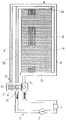
- the actuator 11 assumes different positions. In the position shown, the actuator lies against its left stop under the influence of a compression spring 12 and thus releases an outlet opening 13 of the return line 7b. Under the influence of a wax element, not shown, the actuator 11 can also be moved to the right against the force of the compression spring 12, so that the outlet opening 13 is closed.
Landscapes
- Engineering & Computer Science (AREA)
- Mechanical Engineering (AREA)
- General Engineering & Computer Science (AREA)
- General Details Of Gearings (AREA)
- Fluid-Pressure Circuits (AREA)
Applications Claiming Priority (4)
| Application Number | Priority Date | Filing Date | Title |
|---|---|---|---|
| DE19914105774 DE4105774A1 (de) | 1991-02-23 | 1991-02-23 | Oelkreislauf einer maschine oder eines fahrzeuges |
| DE4105774 | 1991-02-23 | ||
| DE4105773 | 1991-02-23 | ||
| DE4105773 | 1991-02-23 |
Publications (2)
| Publication Number | Publication Date |
|---|---|
| EP0501018A1 true EP0501018A1 (fr) | 1992-09-02 |
| EP0501018B1 EP0501018B1 (fr) | 1995-01-11 |
Family
ID=25901304
Family Applications (1)
| Application Number | Title | Priority Date | Filing Date |
|---|---|---|---|
| EP91119829A Expired - Lifetime EP0501018B1 (fr) | 1991-02-23 | 1991-11-21 | Circuit d'huile d'une machine ou d'un véhicule |
Country Status (3)
| Country | Link |
|---|---|
| EP (1) | EP0501018B1 (fr) |
| DE (1) | DE59104256D1 (fr) |
| ES (1) | ES2067125T3 (fr) |
Cited By (2)
| Publication number | Priority date | Publication date | Assignee | Title |
|---|---|---|---|---|
| FR2896531A1 (fr) * | 2006-01-26 | 2007-07-27 | Peugeot Citroen Automobiles Sa | Dispositif permettant d'accelerer la montee en temperature d'huile de lubrification d'un moteur a combustion interne a turbocompresseur a gaz d'echappement |
| EP2305974A1 (fr) * | 2009-09-24 | 2011-04-06 | Eaton Truck Components Sp. z.o.o. | Système de refroidissement de lubrification et procédé |
Citations (2)
| Publication number | Priority date | Publication date | Assignee | Title |
|---|---|---|---|---|
| US2394672A (en) * | 1943-01-25 | 1946-02-12 | United Aircraft Prod | Valve mechanism |
| DE3806888A1 (de) * | 1987-04-29 | 1989-09-14 | Kloeckner Humboldt Deutz Ag | Oelwaermetauscher, insbesondere als oelkuehler fuer eine brennkraftmaschine |
Family Cites Families (1)
| Publication number | Priority date | Publication date | Assignee | Title |
|---|---|---|---|---|
| JPH01253515A (ja) * | 1987-11-19 | 1989-10-09 | Honda Motor Co Ltd | 内燃機関の動弁装置 |
-
1991
- 1991-11-21 ES ES91119829T patent/ES2067125T3/es not_active Expired - Lifetime
- 1991-11-21 DE DE59104256T patent/DE59104256D1/de not_active Expired - Fee Related
- 1991-11-21 EP EP91119829A patent/EP0501018B1/fr not_active Expired - Lifetime
Patent Citations (2)
| Publication number | Priority date | Publication date | Assignee | Title |
|---|---|---|---|---|
| US2394672A (en) * | 1943-01-25 | 1946-02-12 | United Aircraft Prod | Valve mechanism |
| DE3806888A1 (de) * | 1987-04-29 | 1989-09-14 | Kloeckner Humboldt Deutz Ag | Oelwaermetauscher, insbesondere als oelkuehler fuer eine brennkraftmaschine |
Cited By (3)
| Publication number | Priority date | Publication date | Assignee | Title |
|---|---|---|---|---|
| FR2896531A1 (fr) * | 2006-01-26 | 2007-07-27 | Peugeot Citroen Automobiles Sa | Dispositif permettant d'accelerer la montee en temperature d'huile de lubrification d'un moteur a combustion interne a turbocompresseur a gaz d'echappement |
| WO2007085752A3 (fr) * | 2006-01-26 | 2008-03-27 | Peugeot Citroen Automobiles Sa | Dispositif permettant d'accelerer la montee en temperature d'huile de lubrification d'un moteur a combustion interne a turbocompresseur a gaz d'echappement |
| EP2305974A1 (fr) * | 2009-09-24 | 2011-04-06 | Eaton Truck Components Sp. z.o.o. | Système de refroidissement de lubrification et procédé |
Also Published As
| Publication number | Publication date |
|---|---|
| EP0501018B1 (fr) | 1995-01-11 |
| ES2067125T3 (es) | 1995-03-16 |
| DE59104256D1 (de) | 1995-02-23 |
Similar Documents
| Publication | Publication Date | Title |
|---|---|---|
| EP1482222B1 (fr) | Robinet à voies multiples pour un dispositif de refroidissement/chauffage d'un véhicule | |
| DE19956893A1 (de) | Kühlkreis für einen Verbrennungsmotor | |
| DE112011105266T5 (de) | Fluidsteuersystem | |
| DE102020204271A1 (de) | Wärmetauscheranordnung mit integriertem Ventil und Druckbypass | |
| DE102004020589A1 (de) | Temperaturabhängige Strömungsregelventile für Motorkühlsysteme | |
| DE2623621C2 (de) | Einrichtung zum Beheizen der Bedienungskabine einer Maschine | |
| DE102005048286B4 (de) | Verfahren zum Betrieb eines Kühlsystems für eine Verbrennungskraftmaschine | |
| DE19821256C1 (de) | Verfahren zum Betreiben einer Umlaufflüssigkeitsheizung oder -kühlung und Umlaufflüssigkeitsheizung oder -kühlung | |
| DE69512892T2 (de) | Thermostatgeregeltes mischventil | |
| DE102008004161A1 (de) | Verfahren zum Betreiben einer Brennkraftmaschine | |
| DE2841249C2 (fr) | ||
| WO1988002442A1 (fr) | Echangeur de chaleur pour refroidissement de carburant | |
| DE69924647T2 (de) | Plattenwärmetauscher mit integriertem ventil | |
| EP0501018A1 (fr) | Circuit d'huile d'une machine ou d'un véhicule | |
| DE3241536C2 (fr) | ||
| DE19802362C2 (de) | Verfahren und Einrichtung zur Reduzierung der Wartezeit für das Zapfen von warmem Brauchwasser | |
| DE2943064C2 (de) | Vorrichtung zum Betrieb eines Flüssigkeitskreislaufes | |
| DE10244256A1 (de) | Heizanlage und/oder Kühlanlage mit mindestens einer Wärmequelle | |
| DE4105774A1 (de) | Oelkreislauf einer maschine oder eines fahrzeuges | |
| DE8002070U1 (de) | Kompressorkuehlanordnung | |
| DE19855926A1 (de) | Rücklauf-Raumtemperatur Regelventil | |
| DE2144501C3 (de) | Warmwasserumlaufheizung mit selbsttätiger Temperaturregelung für Räume von Fahrzeugen mit Verbrennungsmotoren, vorzugsweise Schienenfahrzeugen | |
| DE102015217236B4 (de) | Thermostatventil für Kühlmittel von Verbrennungsmotoren | |
| CH622337A5 (en) | Method and installation for heating rooms of a building | |
| AT405329B (de) | Wasserheizanlage mit einem primärwärmetauscher |
Legal Events
| Date | Code | Title | Description |
|---|---|---|---|
| PUAI | Public reference made under article 153(3) epc to a published international application that has entered the european phase |
Free format text: ORIGINAL CODE: 0009012 |
|
| AK | Designated contracting states |
Kind code of ref document: A1 Designated state(s): DE ES FR GB IT SE |
|
| 17P | Request for examination filed |
Effective date: 19921017 |
|
| 17Q | First examination report despatched |
Effective date: 19930721 |
|
| GRAA | (expected) grant |
Free format text: ORIGINAL CODE: 0009210 |
|
| AK | Designated contracting states |
Kind code of ref document: B1 Designated state(s): DE ES FR GB IT SE |
|
| EAL | Se: european patent in force in sweden |
Ref document number: 91119829.9 |
|
| ET | Fr: translation filed | ||
| GBT | Gb: translation of ep patent filed (gb section 77(6)(a)/1977) |
Effective date: 19950119 |
|
| REF | Corresponds to: |
Ref document number: 59104256 Country of ref document: DE Date of ref document: 19950223 |
|
| REG | Reference to a national code |
Ref country code: ES Ref legal event code: FG2A Ref document number: 2067125 Country of ref document: ES Kind code of ref document: T3 |
|
| ITF | It: translation for a ep patent filed | ||
| PLBE | No opposition filed within time limit |
Free format text: ORIGINAL CODE: 0009261 |
|
| STAA | Information on the status of an ep patent application or granted ep patent |
Free format text: STATUS: NO OPPOSITION FILED WITHIN TIME LIMIT |
|
| 26N | No opposition filed | ||
| REG | Reference to a national code |
Ref country code: GB Ref legal event code: IF02 |
|
| PGFP | Annual fee paid to national office [announced via postgrant information from national office to epo] |
Ref country code: ES Payment date: 20081030 Year of fee payment: 18 |
|
| PGFP | Annual fee paid to national office [announced via postgrant information from national office to epo] |
Ref country code: IT Payment date: 20081127 Year of fee payment: 18 Ref country code: SE Payment date: 20081107 Year of fee payment: 18 |
|
| PGFP | Annual fee paid to national office [announced via postgrant information from national office to epo] |
Ref country code: FR Payment date: 20081128 Year of fee payment: 18 |
|
| PGFP | Annual fee paid to national office [announced via postgrant information from national office to epo] |
Ref country code: DE Payment date: 20081211 Year of fee payment: 18 |
|
| PGFP | Annual fee paid to national office [announced via postgrant information from national office to epo] |
Ref country code: GB Payment date: 20081127 Year of fee payment: 18 |
|
| EUG | Se: european patent has lapsed | ||
| GBPC | Gb: european patent ceased through non-payment of renewal fee |
Effective date: 20091121 |
|
| REG | Reference to a national code |
Ref country code: FR Ref legal event code: ST Effective date: 20100730 |
|
| PG25 | Lapsed in a contracting state [announced via postgrant information from national office to epo] |
Ref country code: FR Free format text: LAPSE BECAUSE OF NON-PAYMENT OF DUE FEES Effective date: 20091130 |
|
| PG25 | Lapsed in a contracting state [announced via postgrant information from national office to epo] |
Ref country code: DE Free format text: LAPSE BECAUSE OF NON-PAYMENT OF DUE FEES Effective date: 20100601 |
|
| PG25 | Lapsed in a contracting state [announced via postgrant information from national office to epo] |
Ref country code: GB Free format text: LAPSE BECAUSE OF NON-PAYMENT OF DUE FEES Effective date: 20091121 |
|
| REG | Reference to a national code |
Ref country code: ES Ref legal event code: FD2A Effective date: 20110328 |
|
| PG25 | Lapsed in a contracting state [announced via postgrant information from national office to epo] |
Ref country code: IT Free format text: LAPSE BECAUSE OF NON-PAYMENT OF DUE FEES Effective date: 20091121 |
|
| PG25 | Lapsed in a contracting state [announced via postgrant information from national office to epo] |
Ref country code: SE Free format text: LAPSE BECAUSE OF NON-PAYMENT OF DUE FEES Effective date: 20091122 |
|
| PG25 | Lapsed in a contracting state [announced via postgrant information from national office to epo] |
Ref country code: ES Free format text: LAPSE BECAUSE OF NON-PAYMENT OF DUE FEES Effective date: 20110315 |
|
| PG25 | Lapsed in a contracting state [announced via postgrant information from national office to epo] |
Ref country code: ES Free format text: LAPSE BECAUSE OF NON-PAYMENT OF DUE FEES Effective date: 20091122 |