EP0501041A2 - Procédé et dispositif de mesure de la tension d'un câble - Google Patents
Procédé et dispositif de mesure de la tension d'un câble Download PDFInfo
- Publication number
- EP0501041A2 EP0501041A2 EP91122200A EP91122200A EP0501041A2 EP 0501041 A2 EP0501041 A2 EP 0501041A2 EP 91122200 A EP91122200 A EP 91122200A EP 91122200 A EP91122200 A EP 91122200A EP 0501041 A2 EP0501041 A2 EP 0501041A2
- Authority
- EP
- European Patent Office
- Prior art keywords
- supports
- support points
- rope
- pair
- strand
- Prior art date
- Legal status (The legal status is an assumption and is not a legal conclusion. Google has not performed a legal analysis and makes no representation as to the accuracy of the status listed.)
- Granted
Links
Images

Classifications
-
- G—PHYSICS
- G01—MEASURING; TESTING
- G01L—MEASURING FORCE, STRESS, TORQUE, WORK, MECHANICAL POWER, MECHANICAL EFFICIENCY, OR FLUID PRESSURE
- G01L5/00—Apparatus for, or methods of, measuring force, work, mechanical power, or torque, specially adapted for specific purposes
- G01L5/04—Apparatus for, or methods of, measuring force, work, mechanical power, or torque, specially adapted for specific purposes for measuring tension in flexible members, e.g. ropes, cables, wires, threads, belts or bands
Definitions
- the invention relates to a method for measuring the rope tension in a rope strand, in which the force is measured which is necessary to generate a predetermined deflection of the rope strand between two support points. It also relates to a device for performing such a method.
- the rope tension in a rope strand which is used, for example, as a control rope in an aircraft, is usually measured by means of a mechanical measuring device, which is also known under the name tensiometer.
- a mechanical measuring device which is also known under the name tensiometer.
- the Cable strand brought between two spaced support points, pressed against the support points by a force acting perpendicular to the connecting line of the two support points and centrally between them and thereby deflected from the connecting line of the support points by a predetermined amount.
- the rope tension can then be determined from the force required to generate this deflection using a calibration table.
- the object of the invention is to provide a method with which the rope tension can be determined free of systematic measurement errors and which moreover enables an exact determination of this rope tension without the need for additional information. Furthermore, it is an object of the invention to provide a device which allows such a method to be carried out.
- the invention solves the first object by a method having the characterizing features of claim 1.
- the second object is achieved by a device according to the characterizing part of claim 2.
- Advantageous further developments of the device according to the invention, which above all aim to further optimize and simplify the Serve measuring process are specified in the further claims.
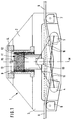
- Figures 1 and 2 show a schematic representation of a device for measuring the rope tension in two mutually perpendicular views, the same components being provided with the same reference numerals in both figures.
- the device consists of a housing 1, which carries a force measuring device to be explained in more detail in its upper part and supports two pairs of supports 4 and 5 or 6 and 7 for a cable strand 8, the tension of which is to be measured, on its lower, remote partial region 3 are.
- the support pairs 4, 5 and 6, 7 are each arranged symmetrically with respect to the vertical central axis M of the housing 1 in the drawing, with different distances, the support pair 4 and 5, as shown in FIG. 1, below the level of the connecting line the support points formed by the support pairs 4.5 and 6.7 can be folded down.
- the upper part 2 of the housing 1 in the drawing carries in a rotatably mounted receiving device 9 a measuring cylinder 11 provided with a measuring block.
- a load cell 12 is arranged.
- the measuring cylinder 11 is held in a height-adjustable manner in the receiving device 9 via an adjusting device, in the case of the exemplary embodiment shown here a spindle nut 13, a drive unit 14 being provided for the adjustment, which can be driven by an electric motor, not shown here.
- the load cell 12 is connected via a signal line 15 to an evaluation and supply unit, not shown in the figure, in which the measurement signals are processed and which provides the required electrical energy and which is partly accommodated in the interior of the housing 2.
- an adjusting device 16 is provided, by means of which the inner pair of supports 4 and 5 can be pivoted from the measuring position into the inactive position and back again.
- the measuring cylinder 11 or the measuring block 10 moves down in a second measuring stroke by an amount h2 which is a multiple of the first measuring stroke h1.
- the force F 2 is measured, which is required to achieve the predetermined deflection of the cable strand 8.
- the measuring device has only one pair of supports, which is held in the direction of the cable strand 8 so as to be longitudinally adjustable, and which thus allows the setting of different spans. It is important in any case that the measuring device has the rigidity required for an exact measurement.
Landscapes
- Physics & Mathematics (AREA)
- General Physics & Mathematics (AREA)
- Force Measurement Appropriate To Specific Purposes (AREA)
Applications Claiming Priority (2)
| Application Number | Priority Date | Filing Date | Title |
|---|---|---|---|
| DE4106266 | 1991-02-28 | ||
| DE4106266A DE4106266A1 (de) | 1991-02-28 | 1991-02-28 | Verfahren zur seilspannungsmessung und vorrichtung zu seiner durchfuehrung |
Publications (3)
| Publication Number | Publication Date |
|---|---|
| EP0501041A2 true EP0501041A2 (fr) | 1992-09-02 |
| EP0501041A3 EP0501041A3 (en) | 1993-03-24 |
| EP0501041B1 EP0501041B1 (fr) | 1995-03-01 |
Family
ID=6426061
Family Applications (1)
| Application Number | Title | Priority Date | Filing Date |
|---|---|---|---|
| EP91122200A Expired - Lifetime EP0501041B1 (fr) | 1991-02-28 | 1991-12-23 | Procédé et dispositif de mesure de la tension d'un câble |
Country Status (4)
| Country | Link |
|---|---|
| US (1) | US5251492A (fr) |
| EP (1) | EP0501041B1 (fr) |
| JP (1) | JP2563152B2 (fr) |
| DE (1) | DE4106266A1 (fr) |
Cited By (2)
| Publication number | Priority date | Publication date | Assignee | Title |
|---|---|---|---|---|
| EP0611706A1 (fr) * | 1993-02-16 | 1994-08-24 | Illinois Tool Works Inc. | Lien pour le cerclage de balles, comportant une partie ondulée, emballage comportant une balle et un pareil lien et appareil pour former un tel lien |
| CN101387600B (zh) * | 2008-10-17 | 2010-10-27 | 东南大学 | 基于混合监测的索结构中索系统的健康监测方法 |
Families Citing this family (17)
| Publication number | Priority date | Publication date | Assignee | Title |
|---|---|---|---|---|
| DE4426405C1 (de) * | 1994-07-26 | 1995-08-31 | Freudenberg Carl Fa | Vorrichtung und Verfahren zur Messung der Reißfestigkeit von textilen Flächengebilden |
| US6029798A (en) * | 1998-03-05 | 2000-02-29 | Jervis B. Webb Company | Methods and system for detecting and determining the location of a chain jam |
| US5932811A (en) * | 1998-06-16 | 1999-08-03 | Comten Industries, Inc. | Portable foam compression tester |
| CA2265193C (fr) * | 1999-03-11 | 2003-11-25 | Pawan R. Gupta | Dispositif et methode d'essai de tension de cables dans des structures en beton |
| US20030066362A1 (en) * | 2001-08-29 | 2003-04-10 | Lee Shih Yuan | Seat belt tension sensor |
| DE102004057675B3 (de) * | 2004-11-29 | 2006-06-22 | Henning Gmbh | Vorrichtung zur Bestimmung der Zugkraft in gespannten Zugmitteln, insbesondere Seilen in Aufzügen |
| DE102007005859A1 (de) * | 2007-02-06 | 2008-08-07 | Siemens Ag | Vorrichtung zum Erkennen eines mechanischen Defekts in einem Draht einer Oberleitung |
| DE102013014265A1 (de) * | 2013-08-27 | 2015-03-05 | Liebherr-Components Biberach Gmbh | Vorrichtung zur Erkennung der Ablegereife eines hochfesten Faserseils beim Einsatz an Hebezeugen |
| US9576475B2 (en) | 2013-09-10 | 2017-02-21 | Southwire Company, Llc | Wireless-enabled tension meter |
| US10288538B2 (en) | 2015-09-30 | 2019-05-14 | Samson Rope Technologies | Non-destructive evaluation of cordage products |
| CN106610329A (zh) * | 2015-10-23 | 2017-05-03 | 中国飞行试验研究院 | 一种机载钢丝绳张力测量装置 |
| US10782198B2 (en) | 2016-07-06 | 2020-09-22 | Greenlee Texron Inc. | Pulley assembly with gauge device and communication environment for messaging |
| CH714596A1 (de) * | 2018-01-26 | 2019-07-31 | Ferag Ag | Messvorrichtung zum Erfassen von Messwerten zur Messung einer Zugspannung in einem Fördersystem, sowie Fördereinheit und Förderanlage. |
| CN109443673B (zh) * | 2018-12-18 | 2024-06-25 | 四川省建筑科学研究院有限公司 | 挠度测量装置及其测量方法 |
| CN110261029A (zh) * | 2019-07-24 | 2019-09-20 | 合肥市尚技体育用品有限公司 | 一种便捷式羽毛球拍磅数检测设备 |
| CN113884233B (zh) * | 2020-07-01 | 2023-12-22 | 中国石油天然气股份有限公司 | 一种管道悬索跨越结构模型主缆索应力调节装置 |
| DE102023134151B4 (de) * | 2023-12-06 | 2025-09-11 | Honigmann Industrielle Elektronik Gmbh | Zugkraftmessvorrichtung |
Family Cites Families (7)
| Publication number | Priority date | Publication date | Assignee | Title |
|---|---|---|---|---|
| DD93642A (fr) * | ||||
| US2659575A (en) * | 1952-10-20 | 1953-11-17 | Standard Oil Dev Co | Live line load weight indicator assembly |
| US2743606A (en) * | 1953-01-28 | 1956-05-01 | Martin Decker Corp | Hydraulic tension sensing and indicating means |
| US4171640A (en) * | 1978-05-16 | 1979-10-23 | W. C. Dillon And Company, Inc. | Tension measuring device |
| US4509376A (en) * | 1979-05-18 | 1985-04-09 | Coles Cranes Limited | Safe load indicator |
| US4492363A (en) * | 1979-12-20 | 1985-01-08 | Niskin Shale J | Multiple pulley sheave assembly with retainer pulleys |
| US4587855A (en) * | 1985-02-15 | 1986-05-13 | Shimpo Kogyo Kabushiki Kaisha | Tensionmeter |
-
1991
- 1991-02-28 DE DE4106266A patent/DE4106266A1/de active Granted
- 1991-12-23 EP EP91122200A patent/EP0501041B1/fr not_active Expired - Lifetime
-
1992
- 1992-02-24 JP JP4036477A patent/JP2563152B2/ja not_active Expired - Lifetime
- 1992-02-27 US US07/842,446 patent/US5251492A/en not_active Expired - Fee Related
Cited By (2)
| Publication number | Priority date | Publication date | Assignee | Title |
|---|---|---|---|---|
| EP0611706A1 (fr) * | 1993-02-16 | 1994-08-24 | Illinois Tool Works Inc. | Lien pour le cerclage de balles, comportant une partie ondulée, emballage comportant une balle et un pareil lien et appareil pour former un tel lien |
| CN101387600B (zh) * | 2008-10-17 | 2010-10-27 | 东南大学 | 基于混合监测的索结构中索系统的健康监测方法 |
Also Published As
| Publication number | Publication date |
|---|---|
| JP2563152B2 (ja) | 1996-12-11 |
| JPH04326030A (ja) | 1992-11-16 |
| EP0501041B1 (fr) | 1995-03-01 |
| US5251492A (en) | 1993-10-12 |
| DE4106266A1 (de) | 1992-09-10 |
| DE4106266C2 (fr) | 1992-12-10 |
| EP0501041A3 (en) | 1993-03-24 |
Similar Documents
| Publication | Publication Date | Title |
|---|---|---|
| EP0501041B1 (fr) | Procédé et dispositif de mesure de la tension d'un câble | |
| EP1498691B1 (fr) | Procédé pour corriger des appareils de mesure de coordonnées | |
| EP2201328B1 (fr) | Procédé pour corriger les valeurs de mesure d'un appareil de mesure de coordonnées et appareil de mesure de coordonnées | |
| DE69920759T2 (de) | Lastmessung | |
| EP2196828B1 (fr) | Appareil de localisation | |
| DE3213319A1 (de) | Einrichtung zum messen von kraft- und momentkomponenten in mehreren richtungen | |
| DE69111289T2 (de) | Reifenprofil-Kraft- und Bewegungsmessvorrichtung. | |
| DE3141767A1 (de) | Kraftwandler | |
| WO2019170483A1 (fr) | Mesure de variatons mécaniques | |
| DE10206259B4 (de) | Verfahren zur Korrektur von Lateralkraftmesswerten | |
| DE2926213C2 (de) | Pyramidenwaage zur Ermittlung von Kräften und Momenten, insbesondere in Windkanälen | |
| DE2106997A1 (de) | Vorrichtung zum Messen von Verschie bungen im zweidimensional Bereich | |
| DE10008202B4 (de) | Anlage zum Prüfen der Biegefestigkeit eines Mastes | |
| DE10120881B4 (de) | Kabelprüfstand für ein Kabel bei Wechselbelastungen | |
| DE3143061C2 (de) | Verfahren zur individuellen Bemessung der Länge der Zugstange und des Segmenthebels eines Überdruckmeßgerätes | |
| DE4327260C2 (de) | Manuell zu betätigender Härteprüfer | |
| EP2720021B1 (fr) | Dispositif de mesure de force | |
| DE102018107720A1 (de) | Messtastelement | |
| EP0365799A2 (fr) | Procédé et dispositif de mesure du courant autour d'une maquette tridimensionnelle à grand volume d'un véhicule terrestre dans une soufflerie | |
| EP0766075B1 (fr) | Procédé pour tester simultanément plusieurs capteurs de forces, en particulier capteurs de pesage, utilisant une charge | |
| DE102008040921A1 (de) | Referenzkörper zur Überprüfung von optischen oder taktilen Messsonden | |
| DE2902798A1 (de) | Verfahren zum herstellen flexibler lagerbuchsen und vorrichtung zur verwendung bei der herstellung von flexiblen lagerbuchsen | |
| DE102022105378B4 (de) | Vorrichtung und Verfahren zur Ermittlung einer Längenänderung und/oder einer Deformation innerhalb eines Bauteils | |
| AT522572B1 (de) | Vorrichtung zur messung von kräften entlang der längsachse eines fahrzeuges | |
| DE102019112909B4 (de) | Prüfstand für die Brücke eines Karosserietunnels und Verwendung eines solchen Prüfstandes |
Legal Events
| Date | Code | Title | Description |
|---|---|---|---|
| PUAI | Public reference made under article 153(3) epc to a published international application that has entered the european phase |
Free format text: ORIGINAL CODE: 0009012 |
|
| AK | Designated contracting states |
Kind code of ref document: A2 Designated state(s): FR GB IT NL |
|
| PUAL | Search report despatched |
Free format text: ORIGINAL CODE: 0009013 |
|
| 17P | Request for examination filed |
Effective date: 19930107 |
|
| AK | Designated contracting states |
Kind code of ref document: A3 Designated state(s): FR GB IT NL |
|
| RAP1 | Party data changed (applicant data changed or rights of an application transferred) |
Owner name: DEUTSCHE AEROSPACE AIRBUS GMBH |
|
| 17Q | First examination report despatched |
Effective date: 19940609 |
|
| GRAA | (expected) grant |
Free format text: ORIGINAL CODE: 0009210 |
|
| AK | Designated contracting states |
Kind code of ref document: B1 Designated state(s): FR GB IT NL |
|
| ITF | It: translation for a ep patent filed | ||
| RAP2 | Party data changed (patent owner data changed or rights of a patent transferred) |
Owner name: DAIMLER-BENZ AEROSPACE AIRBUS GESELLSCHAFT MIT BES |
|
| GBT | Gb: translation of ep patent filed (gb section 77(6)(a)/1977) |
Effective date: 19950426 |
|
| ITF | It: translation for a ep patent filed | ||
| ET | Fr: translation filed | ||
| NLT2 | Nl: modifications (of names), taken from the european patent patent bulletin |
Owner name: DAIMLER-BENZ AEROSPACE AIRBUS GESELLSCHAFT MIT BES |
|
| PGFP | Annual fee paid to national office [announced via postgrant information from national office to epo] |
Ref country code: GB Payment date: 19951214 Year of fee payment: 5 |
|
| PGFP | Annual fee paid to national office [announced via postgrant information from national office to epo] |
Ref country code: FR Payment date: 19951219 Year of fee payment: 5 |
|
| PGFP | Annual fee paid to national office [announced via postgrant information from national office to epo] |
Ref country code: NL Payment date: 19951230 Year of fee payment: 5 |
|
| PLBE | No opposition filed within time limit |
Free format text: ORIGINAL CODE: 0009261 |
|
| STAA | Information on the status of an ep patent application or granted ep patent |
Free format text: STATUS: NO OPPOSITION FILED WITHIN TIME LIMIT |
|
| NLT1 | Nl: modifications of names registered in virtue of documents presented to the patent office pursuant to art. 16 a, paragraph 1 |
Owner name: DAIMLER-BENZ AEROSPACE AIRBUS GESELLSCHAFT MIT BES |
|
| 26N | No opposition filed | ||
| NLT2 | Nl: modifications (of names), taken from the european patent patent bulletin |
Owner name: DAIMLER-BENZ AEROSPACE AIRBUS GESELLSCHAFT MIT BES |
|
| PG25 | Lapsed in a contracting state [announced via postgrant information from national office to epo] |
Ref country code: GB Effective date: 19961223 |
|
| PG25 | Lapsed in a contracting state [announced via postgrant information from national office to epo] |
Ref country code: NL Effective date: 19970701 |
|
| GBPC | Gb: european patent ceased through non-payment of renewal fee |
Effective date: 19961223 |
|
| PG25 | Lapsed in a contracting state [announced via postgrant information from national office to epo] |
Ref country code: FR Effective date: 19970829 |
|
| NLV4 | Nl: lapsed or anulled due to non-payment of the annual fee |
Effective date: 19970701 |
|
| REG | Reference to a national code |
Ref country code: FR Ref legal event code: ST |
|
| PG25 | Lapsed in a contracting state [announced via postgrant information from national office to epo] |
Ref country code: IT Free format text: LAPSE BECAUSE OF NON-PAYMENT OF DUE FEES;WARNING: LAPSES OF ITALIAN PATENTS WITH EFFECTIVE DATE BEFORE 2007 MAY HAVE OCCURRED AT ANY TIME BEFORE 2007. THE CORRECT EFFECTIVE DATE MAY BE DIFFERENT FROM THE ONE RECORDED. Effective date: 20051223 |