EP0501043B1 - Butée encliquetée pour ressort pneumatique - Google Patents
Butée encliquetée pour ressort pneumatique Download PDFInfo
- Publication number
- EP0501043B1 EP0501043B1 EP91122417A EP91122417A EP0501043B1 EP 0501043 B1 EP0501043 B1 EP 0501043B1 EP 91122417 A EP91122417 A EP 91122417A EP 91122417 A EP91122417 A EP 91122417A EP 0501043 B1 EP0501043 B1 EP 0501043B1
- Authority
- EP
- European Patent Office
- Prior art keywords
- air spring
- bumper
- spring according
- post
- fingers
- Prior art date
- Legal status (The legal status is an assumption and is not a legal conclusion. Google has not performed a legal analysis and makes no representation as to the accuracy of the status listed.)
- Expired - Lifetime
Links
- 230000035939 shock Effects 0.000 claims description 12
- 239000004033 plastic Substances 0.000 claims description 10
- 239000012530 fluid Substances 0.000 claims description 9
- 230000003014 reinforcing effect Effects 0.000 claims description 7
- 239000013536 elastomeric material Substances 0.000 claims description 2
- 229910052751 metal Inorganic materials 0.000 claims description 2
- 239000002184 metal Substances 0.000 claims description 2
- 238000010276 construction Methods 0.000 description 5
- 239000011324 bead Substances 0.000 description 3
- 239000000463 material Substances 0.000 description 3
- 238000007789 sealing Methods 0.000 description 3
- 229920001971 elastomer Polymers 0.000 description 2
- 239000000314 lubricant Substances 0.000 description 2
- 238000005461 lubrication Methods 0.000 description 2
- 230000002093 peripheral effect Effects 0.000 description 2
- 229910001209 Low-carbon steel Inorganic materials 0.000 description 1
- 229910000831 Steel Inorganic materials 0.000 description 1
- 239000006096 absorbing agent Substances 0.000 description 1
- 229910052782 aluminium Inorganic materials 0.000 description 1
- XAGFODPZIPBFFR-UHFFFAOYSA-N aluminium Chemical compound [Al] XAGFODPZIPBFFR-UHFFFAOYSA-N 0.000 description 1
- 238000005219 brazing Methods 0.000 description 1
- 239000000806 elastomer Substances 0.000 description 1
- 238000009434 installation Methods 0.000 description 1
- 229920000728 polyester Polymers 0.000 description 1
- 229920000642 polymer Polymers 0.000 description 1
- 239000010959 steel Substances 0.000 description 1
Images

Classifications
-
- F—MECHANICAL ENGINEERING; LIGHTING; HEATING; WEAPONS; BLASTING
- F16—ENGINEERING ELEMENTS AND UNITS; GENERAL MEASURES FOR PRODUCING AND MAINTAINING EFFECTIVE FUNCTIONING OF MACHINES OR INSTALLATIONS; THERMAL INSULATION IN GENERAL
- F16F—SPRINGS; SHOCK-ABSORBERS; MEANS FOR DAMPING VIBRATION
- F16F9/00—Springs, vibration-dampers, shock-absorbers, or similarly-constructed movement-dampers using a fluid or the equivalent as damping medium
- F16F9/02—Springs, vibration-dampers, shock-absorbers, or similarly-constructed movement-dampers using a fluid or the equivalent as damping medium using gas only or vacuum
- F16F9/04—Springs, vibration-dampers, shock-absorbers, or similarly-constructed movement-dampers using a fluid or the equivalent as damping medium using gas only or vacuum in a chamber with a flexible wall
-
- B—PERFORMING OPERATIONS; TRANSPORTING
- B60—VEHICLES IN GENERAL
- B60G—VEHICLE SUSPENSION ARRANGEMENTS
- B60G7/00—Pivoted suspension arms; Accessories thereof
- B60G7/04—Buffer means for limiting movement of arms
-
- B—PERFORMING OPERATIONS; TRANSPORTING
- B60—VEHICLES IN GENERAL
- B60G—VEHICLE SUSPENSION ARRANGEMENTS
- B60G11/00—Resilient suspensions characterised by arrangement, location or kind of springs
- B60G11/26—Resilient suspensions characterised by arrangement, location or kind of springs having fluid springs only, e.g. hydropneumatic springs
- B60G11/27—Resilient suspensions characterised by arrangement, location or kind of springs having fluid springs only, e.g. hydropneumatic springs wherein the fluid is a gas
-
- F—MECHANICAL ENGINEERING; LIGHTING; HEATING; WEAPONS; BLASTING
- F16—ENGINEERING ELEMENTS AND UNITS; GENERAL MEASURES FOR PRODUCING AND MAINTAINING EFFECTIVE FUNCTIONING OF MACHINES OR INSTALLATIONS; THERMAL INSULATION IN GENERAL
- F16B—DEVICES FOR FASTENING OR SECURING CONSTRUCTIONAL ELEMENTS OR MACHINE PARTS TOGETHER, e.g. NAILS, BOLTS, CIRCLIPS, CLAMPS, CLIPS OR WEDGES; JOINTS OR JOINTING
- F16B37/00—Nuts or like thread-engaging members
- F16B37/04—Devices for fastening nuts to surfaces, e.g. sheets, plates
- F16B37/041—Releasable devices
- F16B37/043—Releasable devices with snap action
-
- F—MECHANICAL ENGINEERING; LIGHTING; HEATING; WEAPONS; BLASTING
- F16—ENGINEERING ELEMENTS AND UNITS; GENERAL MEASURES FOR PRODUCING AND MAINTAINING EFFECTIVE FUNCTIONING OF MACHINES OR INSTALLATIONS; THERMAL INSULATION IN GENERAL
- F16F—SPRINGS; SHOCK-ABSORBERS; MEANS FOR DAMPING VIBRATION
- F16F9/00—Springs, vibration-dampers, shock-absorbers, or similarly-constructed movement-dampers using a fluid or the equivalent as damping medium
- F16F9/02—Springs, vibration-dampers, shock-absorbers, or similarly-constructed movement-dampers using a fluid or the equivalent as damping medium using gas only or vacuum
- F16F9/04—Springs, vibration-dampers, shock-absorbers, or similarly-constructed movement-dampers using a fluid or the equivalent as damping medium using gas only or vacuum in a chamber with a flexible wall
- F16F9/05—Springs, vibration-dampers, shock-absorbers, or similarly-constructed movement-dampers using a fluid or the equivalent as damping medium using gas only or vacuum in a chamber with a flexible wall the flexible wall being of the rolling diaphragm type
- F16F9/052—Springs, vibration-dampers, shock-absorbers, or similarly-constructed movement-dampers using a fluid or the equivalent as damping medium using gas only or vacuum in a chamber with a flexible wall the flexible wall being of the rolling diaphragm type characterised by the bumper
-
- B—PERFORMING OPERATIONS; TRANSPORTING
- B60—VEHICLES IN GENERAL
- B60G—VEHICLE SUSPENSION ARRANGEMENTS
- B60G2202/00—Indexing codes relating to the type of spring, damper or actuator
- B60G2202/10—Type of spring
- B60G2202/14—Plastic spring, e.g. rubber
- B60G2202/143—Plastic spring, e.g. rubber subjected to compression
-
- B—PERFORMING OPERATIONS; TRANSPORTING
- B60—VEHICLES IN GENERAL
- B60G—VEHICLE SUSPENSION ARRANGEMENTS
- B60G2202/00—Indexing codes relating to the type of spring, damper or actuator
- B60G2202/10—Type of spring
- B60G2202/15—Fluid spring
- B60G2202/152—Pneumatic spring
-
- B—PERFORMING OPERATIONS; TRANSPORTING
- B60—VEHICLES IN GENERAL
- B60G—VEHICLE SUSPENSION ARRANGEMENTS
- B60G2204/00—Indexing codes related to suspensions per se or to auxiliary parts
- B60G2204/40—Auxiliary suspension parts; Adjustment of suspensions
- B60G2204/45—Stops limiting travel
- B60G2204/4502—Stops limiting travel using resilient buffer
-
- B—PERFORMING OPERATIONS; TRANSPORTING
- B60—VEHICLES IN GENERAL
- B60G—VEHICLE SUSPENSION ARRANGEMENTS
- B60G2206/00—Indexing codes related to the manufacturing of suspensions: constructional features, the materials used, procedures or tools
- B60G2206/01—Constructional features of suspension elements, e.g. arms, dampers, springs
- B60G2206/40—Constructional features of dampers and/or springs
- B60G2206/42—Springs
- B60G2206/424—Plunger or top retainer construction for bellows or rolling lobe type air springs
Definitions
- the invention relates to air spring according to the preamble of claim 1.
- Pneumatic springs commonly referred to as air springs
- air springs have been used for motor vehicles and various machines and other equipment for a number of years to provide cushioning between movable parts, primarily to absorb shock loads imparted thereon.
- the air spring usually consists of a flexible rubber sleeve which extends between a pair of end members which contains a supply of compressed air and may have one or more pistons located within the flexible sleeve.
- the end members mount the air spring on spaced components or parts of the vehicle or equipment on which the air spring is mounted.
- the internal pressurized fluid which is generally air, absorbs most of the shock impressed upon or experienced by one of the spaced end members by which the air spring is mounted, with the end members moving axially towards and away from each other upon absorbing the imparted shock. Examples of such air springs are shown in U.S. Patent Nos. 4,852,861 and 4,946,144.
- U.S. Patent No. 4,478,396 discloses an elastomeric bumper which is mounted on the top of a vehicle strut.
- U.S. Patent No. 3,658,314 discloses a fluid shock absorber having an elastomeric member mounted between two concentrically movable tubes with an elastomeric bumper mounted beneath the inner tube to absorb impact from the tube.
- U.S. Patent No. 4,342,264 shows another type of air spring using an elastomeric bumper mounted on one of the end members.
- U.S. Patent No. 4,218,599 discloses a polymer spring for use in a drawer of a cabinet to ensure that when the drawer is closed it does not rebound to a partially opened position.
- An objective of the invention includes providing an improved air spring construction for motor vehicles and other types of equipment having spaced movable end members and a plastic bumper mounted within a pressurized chamber extending between the end members for absorbing excessive shock imparted on the end members.
- a further objective of the invention is to provide such an improved air spring in which the shock absorbing bumper is formed of a high strength plastic material to absorb sudden large deflections and to act as a backup device in case of air spring failure.
- Still another objective of the invention is to provide such an improved air spring in which the internal bumper is snap-fitted into position on a stud which is attached to one of the end members and extends into the fluid chamber, eliminating the use of expensive installation equipment and lubrication heretofore required for installing elastomeric bumpers on the mounting studs.
- a still further objective of the invention is to provide such an improved air spring which is lighter in weight, easier and less expensive to assemble, and which can carry greater loads at equivalent deflections than the heretofore used elastomeric bumpers.
- a further objective of the invention is to provide such an improved air spring in which the internal bumper is an integral one-piece member formed of plastic having concentrically spaced inner and outer walls connected by radially extending reinforcing ribs.
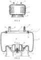
- Air spring 1 includes an upper end cap member and an opposed axially spaced piston member, indicated generally at 2 and 3, respectively (FIG. 2).
- Piston 3 is of a usual construction, preferably having an inverted generally bowl-shaped configuration formed of a suitable material such as aluminum, steel, high strength plastic or the like. Piston 3 includes a base 4 and an annular wall 5 extending downwardly from the base, terminating in a peripheral edge 6. A central supporting structure 7 is joined with and extends downwardly from base 4.
- a flexible sleeve which is indicated generally at 10 terminates in a lower bead 11 which is clamped on base 4 of piston 3 by a clamping plate 12 in an air tight sealing relationship with piston 3.
- the other end of sleeve 10 has an end bead 13 which is secured in a curled marginal edge 14 of mounting end cap 2 in an air tight sealing relationship therewith, providing a fluid tight chamber 15 within elastomeric sleeve 10.
- Other types of end sealing arrangements may be utilized without effecting the concept of the invention, such as shown in U.S. Patent Nos. 4,852,861, 4,787,606 and 4,946,144, which are assigned to the same entity as is the present invention, which do not require a beaded end seal.
- a source of pressurized air or other fluid communicates with chamber 15 through a hollow bore 17 of a mounting stud 18 extending outwardly from end plate 2.
- One or more additional mounting studs 19 are mounted on end cap 2 and extend upwardly therefrom for mounting air spring 1 on a vehicle, machine tool or other application in which it is to be used.
- an improved snap-on bumper indicated generally at 20 is mounted on base 4 of piston 3 and extends upwardly therefrom into chamber 15. Bumper 20 engages end cap 2 in the event of a failure of the pressurized fluid within air chamber 15, or assists in absorbing excessive shock forces exerted on either of the end members.
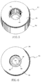
- Bumper 20 includes inner and outer generally cylindrical walls 23 and 24, respectively, concentrically arranged with each other which terminate in an integral dome-shaped connecting top wall 25.
- a plurality of radially extending reinforcing ribs 26 are formed integrally with inner and outer walls 23 and 24 and extend therebetween to provide a rigid integrally formed one-piece bumper member.
- a second plurality of reinforcing ribs 27 are located between adjacent pairs of reinforcing ribs 26, and extend radially inwardly toward inner wall 23 from outer wall 24 only a short distance to provide increased strength for outer wall 24.
- Inner wall 23 terminates in an annular base 29 which lies in the same plane as does the annular peripheral edge 30 of outer wall 24 as shown particularly in FIG. 6.
- Plate 12 is secured in a fluid tight clamping relationship with sleeve bead 11 by a threaded clamping stud 32 which extends through an opening 33 formed in base 4 in cooperation with an end cap, indicated generally at 34.
- Cap 34 preferably is formed of a mild steel and is secured to clamp plate 12 by brazing at 35.
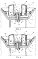
- the interior of end cap 34 has a threaded bore 37 for threaded connection with threaded shaft 38 of clamping stud 32, and together form a central bumper attachment post 36.
- Other types of attachment posts 36 may be utilized than that shown in the drawings, without effecting the concept of the invention.
- post 36 could be molded of a high strength plastic integral with a plastic piston member 3, or could be welded or brazed to an inside surface of a metal piston member. Both of these constructions would eliminate an opening being required through the base of the piston.
- end cap 34 is formed with an enlarged outer end 39 which forms an annular undercut 40 adjacent the outwardly tapering annular side wall 41 of post 36.
- bumper 20 is formed with a plurality of flexible angled fingers 43 which extend upwardly inwardly into a hollow interior 44 formed by inner wall 23.
- Arcuate edges preferably have arcuate lengths or angles of approximately 75 degrees each, and are inclined inwardly and form an included angle of approximately 20 degrees with inner wall 23.
- Post 36 forms a vertically extending member located within the interior 44 of bumper 20 with flexible fingers 43 enabling bumper 20 to be snap-fitted on end cap 34 of the mounting post as shown in FIGS. 3 and 4, by flexing outwardly as it is being forced downwardly on the mounting post.
- the flexibility of the fingers will enable them to snap into position in undercut 40.
- annular base 29 will seat upon clamp plate 12, firmly mounting bumper 20 in position within pressure chamber 15.
- fingers 43 are secured between undercut 40 and clamp plate 12 and the flexibility of fingers 43 retain the arcuate edges thereof, in undercut 40, with the slope surfaces of the fingers lying along tapered side wall 41 of end cap 34.
- Bumper 20 is formed of a high strength polyester elastomer or plastic such as sold under the trademark HYTREL, by Du Pont de Nemorus Company of Wilmington, Delaware.
- the type of HYTREL found most suitable is Dupont's grade 8238 which has a hardness Durometer D of 82, a tensile strength at break of 6800 psi and an elongation at break of 350%.
- Bumper 20 also may be configured square, cloverleaf etc., and need not be cylindrical as described above and shown in the drawings, without effecting the concept of the invention.
- the improved air spring of the invention and in particular snap-on bumper 20 thereof, enables the bumper to be installed easily on center post 36 by snap-fitting the bumper in a vertical downward direction over enlarged end 39 of the post, with flexible fingers 43 snapping into position into undercut 40 formed beneath enlarged end 39.
- This provides a bumper and resulting air spring, which is lighter in weight than prior art bumpers formed of an elastomeric material and, most importantly, enables the bumper to be snap-fitted into position without requiring lubricant and extra equipment heretofore required for installing the elastomeric bumper.
- the high strength plastic of bumper 20 enables it to absorb greater load shocks at equivalent deflections than that absorbed by the prior elastomeric bumpers.
- the improved snap-on bumper is simplified, provides an effective, safe, inexpensive, and efficient device which achieves all the enumerated objectives, provides for eliminating difficulties encountered with prior devices, and solves problems and obtains new results in the art.
Landscapes
- Engineering & Computer Science (AREA)
- General Engineering & Computer Science (AREA)
- Mechanical Engineering (AREA)
- Fluid-Damping Devices (AREA)
Claims (16)
- Ressort pneumatique (1) destiné à être monté entre des structures de support espacées l'une de l'autre, le ressort pneumatique (1) comprenant une paire d'éléments terminaux (2, 3) espacés l'un de l'autre, une gaine flexible (10) réalisée à partir d'une matière élastomérique, en engagement étanche avec les éléments terminaux (2, 3) de manière à former entre ceux-ci une chambre (15) à fluide sous pression, et comprenant en outre une colonne (36) qui est montée sur l'un (3) des éléments terminaux (2, 3) et s'étend vers l'intérieur de la chambre (15) à fluide et porte une butée-amortisseur (20) montée sur la colonne (36) en vue d'un engagement d'impact possible avec l'autre (2) desdits éléments terminaux (2, 3); où la colonne (36) présente une partie terminale élargie (39) et un dégagement (40) taillé sous ladite partie terminale (39), et où la butée est constituée par un élément monobloc comprenant une embase (29) conformée avec une ouverture centrale, ladite ouverture centrale étant emboîtée par-dessus la partie terminale élargie (39) de la colonne (36), de façon telle que ladite butée (20) se loge dans le dégagement (40) ménagé dans ladite colonne (36);
caractérisé en ce que la butée (20) est fabriquée en une matière plastique et comprend des parois intérieure et extérieure (23, 24), qui se terminent dans une paroi intégrée supérieure (25), et en ce que ladite ouverture centrale est définie par plusieurs doigts flexibles (43) espacés circonférentiellement les uns des autres, s'étendant vers le haut, vers l'intérieur de l'espace intérieur creux (44) formé par la paroi intérieure (23), lesdits doigts (43) s'encliquetant sur ladite colonne (36). - Ressort pneumatique selon la revendication 1, caractérisé en ce que plusieurs premières nervures (26) de renfort s'étendent radialement entre lesdites parois espacées (23, 24) et sont reliées à celles-ci.
- Ressort pneumatique selon la revendication 2, caractérisé en ce que la paroi intérieure (23) définit un alésage central; et dans lequel l'embase (29) fait partie intégrante de ladite paroi intérieure (23), et les doigts flexibles (43) s'étendent vers l'intérieur dudit alésage central.
- Ressort pneumatique selon la revendication 3, caractérisé en ce que les doigts (43) présentent une forme d'arc et sont inclinés vers l'intérieur, les uns vers les autres.
- Ressort pneumatique selon la revendication 3, caractérisé en ce que les doigts (43) se terminent sous forme de bords arqués (46) se situant dans un cercle imaginaire; et dans lequel les bords courbes se logent dans le dégagement (40) ménagé dans la colonne (36) et entrent en engagement avec la partie terminale élargie de ladite colonne (36).
- Ressort pneumatique selon la revendication 1, caractérisé en ce que quatre doigts (43) en forme d'arc, circonférentiellement espacés les uns des autres, sont prévus; et dans lequel chacun desdits doigts (43) couvre un angle d'arc d'environ 75°.
- Ressort pneumatique selon la revendication 4, caractérisé en ce que chacun des doigts flexibles (43) définit en conjonction avec les parois intérieures (23) un angle inclus d'environ 20°.
- Ressort pneumatique selon la revendication 1, caractérisé en ce que la paroi supérieure (25) présente la forme d'un dôme.
- Ressort pneumatique selon la revendication 2, caractérisé en ce que plusieurs secondes nervures (27) de renfort sont formées sur la paroi extérieure (24) et sont logées entre des paires correspondantes des premières nervures (26) de renfort et s'étendent radialement vers la paroi intérieure (23).
- Ressort pneumatique selon la revendication 3, caractérisé en ce que la paroi extérieure (24) se termine sous forme d'un bord annulaire (30); et dans lequel ledit bord annulaire (30) et ladite embase (29) se situent dans un plan commun.
- Ressort pneumatique selon la revendication 1, caractérisé en ce que la colonne (36) comprend une tige centrale montée sur ledit un élément terminal, et un chapeau d'embout séparé monté sur ladite tige, formant la partie terminale élargie.
- Ressort pneumatique selon la revendication 1, caractérisé en ce que le chapeau d'embout (34) est réalisé en métal; et dans lequel la tige comporte une extrémité filetée sur laquelle doit être monté le chapeau d'embout.
- Ressort pneumatique selon la revendication 1, caractérisé en ce que l'un des éléments terminaux (2, 3) est un piston.
- Ressort pneumatique selon la revendication 1, caractérisé en ce que la butée (20) présente une dureté durométrique D de 82 environ.
- Ressort pneumatique selon la revendication 1, caractérisé en ce que la butée (20) présente une résistance à la traction de 6800 psi environ à la rupture.
- Ressort pneumatique selon la revendication 1, caractérisé en ce que la butée (20) présente un allongement à la rupture de 350 % environ.
Applications Claiming Priority (2)
| Application Number | Priority Date | Filing Date | Title |
|---|---|---|---|
| US661280 | 1991-02-26 | ||
| US07/661,280 US5201500A (en) | 1991-02-26 | 1991-02-26 | Snap-on bumper for air spring |
Publications (2)
| Publication Number | Publication Date |
|---|---|
| EP0501043A1 EP0501043A1 (fr) | 1992-09-02 |
| EP0501043B1 true EP0501043B1 (fr) | 1995-08-30 |
Family
ID=24652942
Family Applications (1)
| Application Number | Title | Priority Date | Filing Date |
|---|---|---|---|
| EP91122417A Expired - Lifetime EP0501043B1 (fr) | 1991-02-26 | 1991-12-31 | Butée encliquetée pour ressort pneumatique |
Country Status (11)
| Country | Link |
|---|---|
| US (1) | US5201500A (fr) |
| EP (1) | EP0501043B1 (fr) |
| JP (1) | JP3174377B2 (fr) |
| KR (1) | KR100259391B1 (fr) |
| AU (1) | AU649292B2 (fr) |
| BR (1) | BR9200624A (fr) |
| CA (1) | CA2060644C (fr) |
| DE (1) | DE69112603T2 (fr) |
| ES (1) | ES2076456T3 (fr) |
| MX (1) | MX9102793A (fr) |
| NZ (1) | NZ240968A (fr) |
Cited By (1)
| Publication number | Priority date | Publication date | Assignee | Title |
|---|---|---|---|---|
| WO2021007795A1 (fr) * | 2019-07-17 | 2021-01-21 | Zhejiang Sanhua Intelligent Controls Co., Ltd. | Amortisseur de vibrations |
Families Citing this family (44)
| Publication number | Priority date | Publication date | Assignee | Title |
|---|---|---|---|---|
| IT1271517B (it) * | 1993-10-11 | 1997-05-30 | Psa Sist Antivibranti Spa | Pistone per molle pneumatiche particolarmente per sospensioni di veicoli |
| US5535994A (en) * | 1993-11-30 | 1996-07-16 | The Goodyear Tire & Rubber Company | Composite air spring piston |
| US5921532A (en) * | 1994-10-07 | 1999-07-13 | Neway Anchorlok International, Inc. | Air spring with internal support member |
| DE29619081U1 (de) * | 1996-11-04 | 1997-01-09 | ContiTech Luftfedersysteme GmbH, 30165 Hannover | Rollbalg-Luftfeder |
| US5795094A (en) * | 1996-11-19 | 1998-08-18 | Lockheed Martin Corporation | Composite metallic tension fitting |
| CA2281694C (fr) * | 1996-12-17 | 2005-08-09 | Btr Industries Limited | Ressort elastomere renforce |
| CA2229629C (fr) * | 1997-03-13 | 2007-08-14 | The Goodyear Tire & Rubber Company | Composition de courroies a haut module et courroies obtenues avec cette composition |
| US6070861A (en) * | 1998-03-12 | 2000-06-06 | Bridgestone/Firestone, Inc | Bumper extension for use with a bumper on an air spring |
| US6199837B1 (en) | 1998-05-01 | 2001-03-13 | Bridgestone/Firestone, Inc. | Thermoplastic elastomer air spring |
| US5934652A (en) * | 1998-05-28 | 1999-08-10 | The Goodyear Tire & Rubber Company | Air spring bumper and method of mounting |
| US5941510A (en) | 1998-06-30 | 1999-08-24 | Bridgestone/Firestone, Inc. | Metal/elastomeric bumper for air springs |
| US6113081A (en) * | 1998-06-30 | 2000-09-05 | Bridgestone/Firestone, Inc. | Snap-on bumper for air spring |
| SE9802767D0 (sv) * | 1998-08-19 | 1998-08-19 | Anders Sjoelund | Framvagnsfjädring |
| NL1010384C2 (nl) * | 1998-10-23 | 2000-04-26 | Weweler Nv | Luchtveer, in het bijzonder voor een luchtveersysteem voor een wielas van een voertuig. |
| US6733022B2 (en) * | 1998-12-01 | 2004-05-11 | Curtis S. Bradshaw | Air bag for sprint car |
| EP1179146B1 (fr) | 1999-05-12 | 2004-03-31 | The Goodyear Tire & Rubber Company | Ressort pneumatique et dispositif de retenue pour ressort pneumatique |
| US6109598A (en) * | 1999-06-29 | 2000-08-29 | Bridgestone/Firestone, Inc. | Air spring bumper utilizing a combination of materials |
| DE50006950D1 (de) | 1999-07-07 | 2004-08-05 | Phoenix Ag | Luftfederanordnung |
| US6234460B1 (en) | 1999-08-23 | 2001-05-22 | The Goodyear Tire & Rubber Company | Push-on air spring bumper |
| US6682058B1 (en) | 1999-12-09 | 2004-01-27 | Phoenix Ag | Air-spring assembly |
| US6386525B1 (en) * | 2000-10-24 | 2002-05-14 | The Boler Company. | Dual volume air spring for suspensions |
| US6746004B2 (en) | 2001-12-05 | 2004-06-08 | Bfs Diversified Products, Llc | Vehicle air spring assembly |
| US7040520B2 (en) * | 2002-09-12 | 2006-05-09 | Illinois Tool Works Inc. | Fan motor suspension mount for a combustion-powered tool |
| KR20040048784A (ko) * | 2002-12-12 | 2004-06-10 | 조영채 | 화물차량의 적재함용 에어 스프링 |
| ITMI20050211A1 (it) * | 2005-02-14 | 2006-08-15 | Stuani S P A | Pistone perfezionato per molle ad aria applicabile a sospensioni di autoveicoli rimorchi semirimorchi |
| US8978841B2 (en) * | 2005-07-06 | 2015-03-17 | Wabtec Holding Corp | Universal brake assembly |
| US7931130B2 (en) * | 2005-07-06 | 2011-04-26 | Wabtec Holding Corp | Universal brake assembly |
| US7896320B2 (en) * | 2007-06-19 | 2011-03-01 | Bfs Diversified Products, Llc | Jounce bumper assembly and gas spring assembly including same |
| US20090200717A1 (en) * | 2008-02-08 | 2009-08-13 | Veyance Technologies, Inc. | Air spring piston |
| RU2012109137A (ru) | 2009-08-19 | 2013-09-27 | Акташ Хава Сюспансийон Системлери Санайи Ве Тиджарет Аноним Ширкети | Амортизатор для пневматической пружины |
| TR201000543A2 (tr) | 2010-01-26 | 2011-01-21 | Aktaş Hava Süspansi̇yon Si̇stemleri̇ Sanayi̇ Ve Ti̇caret A.Ş. | Havalı süspansiyon tertibatlarında kullanılan, termoplastik malzeme esaslı takozlu alt tas |
| WO2012097354A1 (fr) * | 2011-01-14 | 2012-07-19 | Firestone Industrial Products Company, Llc | Ensemble amortisseur de cahots et ensemble ressort à gaz le comprenant |
| WO2012148892A1 (fr) * | 2011-04-25 | 2012-11-01 | Wabtec Holding Corp. | Agencement et procédé permettant de sceller les extrémités d'un ressort pneumatique |
| DE102011055351A1 (de) * | 2011-11-15 | 2013-05-16 | Contitech Luftfedersysteme Gmbh | Abrollkolben für einen Luftfederbalg |
| CN102562902B (zh) * | 2012-02-22 | 2015-12-16 | 喜临门家具股份有限公司 | 一种环接式气压弹簧 |
| WO2014036316A1 (fr) * | 2012-08-29 | 2014-03-06 | Firestone Industrial Products Company, Llc | Eléments d'extrémité et blocs ressorts à gaz les contenant |
| EP2903839B1 (fr) * | 2012-10-02 | 2019-06-05 | Basf Se | Ensemble de butée anti-chocs |
| US10578181B2 (en) * | 2015-11-09 | 2020-03-03 | Firestone Industrial Products Company, Llc | Flexible spring members as well as gas spring assemblies and methods of manufacture |
| JP2017110753A (ja) * | 2015-12-17 | 2017-06-22 | アイシン精機株式会社 | 空気ばね |
| CN106985407B (zh) * | 2016-01-21 | 2019-05-07 | 株洲时代新材料科技股份有限公司 | 一种制造空气弹簧的方法 |
| US10618366B2 (en) * | 2016-07-08 | 2020-04-14 | Continental Automotive Systems, Inc. | Vehicle air strut with twist lock closure cover |
| US10830306B2 (en) * | 2016-12-30 | 2020-11-10 | Firestone Industrial Products Company, Llc | Jounce bumper assemblies as well as gas spring assemblies including same |
| JP2018109434A (ja) * | 2017-01-05 | 2018-07-12 | 東洋ゴム工業株式会社 | 空気ばね |
| US10690209B2 (en) * | 2018-08-02 | 2020-06-23 | Contitech Luftfedersysteme Gmbh | Press-on composite bumper to composite piston |
Family Cites Families (14)
| Publication number | Priority date | Publication date | Assignee | Title |
|---|---|---|---|---|
| GB964138A (en) * | 1961-12-22 | 1964-07-15 | Firestone Tire & Rubber Co | Air springs for suspension systems and bellows therefor |
| US3565456A (en) * | 1968-12-16 | 1971-02-23 | Motor Coach Ind Ltd | Rear suspension for vehicles |
| US3658314A (en) * | 1969-08-18 | 1972-04-25 | Clevite Corp | Elastomeric fluid shock absorber |
| US4218599A (en) * | 1977-11-30 | 1980-08-19 | Steelcase Inc. | Polymer spring |
| US4342264A (en) * | 1980-02-28 | 1982-08-03 | Bi-Modal Corporation | Convertible rail-highway semi-trailer fluid suspension |
| JPS5865342A (ja) * | 1981-10-09 | 1983-04-19 | Nissan Motor Co Ltd | 弾性支持構造 |
| US4506910A (en) * | 1982-09-21 | 1985-03-26 | Granning Suspensions, Inc. | Automotive vehicle suspension |
| US4639159A (en) * | 1983-03-05 | 1987-01-27 | Trw Ehrenreich Gmbh & Co. Kg | Device for attaching bellows to a cylindrical member |
| US4787606A (en) * | 1987-06-17 | 1988-11-29 | The Firestone Tire & Rubber Company | Beadless air spring |
| EP0320149A1 (fr) * | 1987-12-09 | 1989-06-14 | Lord Corporation | Support à une plaque à montage rapide |
| US4805886A (en) * | 1988-04-11 | 1989-02-21 | Chrysler Motors Corporation | Jounce bumper assembly for vehicle suspension strut |
| US4852861A (en) * | 1988-12-29 | 1989-08-01 | The Firestone Tire & Rubber Company | End cap assembly for air spring |
| US4925224A (en) * | 1989-03-06 | 1990-05-15 | Romeo-Rim, Inc. | Energy absorbing vehicle bumper |
| US4946144A (en) * | 1989-03-30 | 1990-08-07 | Bridgestone/Firestone, Inc. | External clamping band for air spring |
-
1991
- 1991-02-26 US US07/661,280 patent/US5201500A/en not_active Expired - Lifetime
- 1991-12-05 AU AU88822/91A patent/AU649292B2/en not_active Expired
- 1991-12-13 NZ NZ240968A patent/NZ240968A/en not_active IP Right Cessation
- 1991-12-26 MX MX9102793A patent/MX9102793A/es not_active IP Right Cessation
- 1991-12-31 ES ES91122417T patent/ES2076456T3/es not_active Expired - Lifetime
- 1991-12-31 EP EP91122417A patent/EP0501043B1/fr not_active Expired - Lifetime
- 1991-12-31 DE DE69112603T patent/DE69112603T2/de not_active Expired - Lifetime
-
1992
- 1992-01-07 KR KR1019920000063A patent/KR100259391B1/ko not_active Expired - Fee Related
- 1992-01-27 JP JP03404092A patent/JP3174377B2/ja not_active Expired - Fee Related
- 1992-02-24 CA CA002060644A patent/CA2060644C/fr not_active Expired - Fee Related
- 1992-02-25 BR BR929200624A patent/BR9200624A/pt not_active IP Right Cessation
Cited By (1)
| Publication number | Priority date | Publication date | Assignee | Title |
|---|---|---|---|---|
| WO2021007795A1 (fr) * | 2019-07-17 | 2021-01-21 | Zhejiang Sanhua Intelligent Controls Co., Ltd. | Amortisseur de vibrations |
Also Published As
| Publication number | Publication date |
|---|---|
| AU8882291A (en) | 1992-08-27 |
| BR9200624A (pt) | 1992-10-27 |
| EP0501043A1 (fr) | 1992-09-02 |
| KR920016741A (ko) | 1992-09-25 |
| DE69112603T2 (de) | 1996-02-15 |
| CA2060644C (fr) | 2002-11-19 |
| CA2060644A1 (fr) | 1992-08-27 |
| DE69112603D1 (de) | 1995-10-05 |
| JP3174377B2 (ja) | 2001-06-11 |
| JPH04307134A (ja) | 1992-10-29 |
| MX9102793A (es) | 1992-08-01 |
| US5201500A (en) | 1993-04-13 |
| AU649292B2 (en) | 1994-05-19 |
| ES2076456T3 (es) | 1995-11-01 |
| NZ240968A (en) | 1993-07-27 |
| KR100259391B1 (ko) | 2000-06-15 |
Similar Documents
| Publication | Publication Date | Title |
|---|---|---|
| EP0501043B1 (fr) | Butée encliquetée pour ressort pneumatique | |
| EP0943836B1 (fr) | Extension pour un pare-chocs d'un ressort pneumatique | |
| EP0969223B1 (fr) | Pare-choc à encliquetage, pour ressort pneumatique | |
| EP0969224B1 (fr) | Un pare-choc métallique/élastomerique pour ressorts pneumatiques | |
| EP1190183B1 (fr) | Butee elastique de suspension pneumatique utilisant une combinaison de matieres | |
| EP0318696B1 (fr) | Sustension à ressort à air avec isolation à deux voies | |
| US5934652A (en) | Air spring bumper and method of mounting | |
| US5456454A (en) | Support bearing for automotive vehicles | |
| EP0291720B1 (fr) | Système de suspension pour véhicules comportant un élément formant support isolateur et organe d'étanchéité de ressort pneumatique | |
| US5431260A (en) | Shock absorber having an elastic gasket upper mounting assembly | |
| US6186486B1 (en) | Jounce bumper plate | |
| EP2088009A2 (fr) | Piston à ressort pneumatique | |
| EP0364411B1 (fr) | Dispositif de suspension pour véhicules comprenant un amortisseur telescopique et un ressort à air | |
| CN110792715B (zh) | 组合活塞的压紧组合缓冲器 | |
| JP3695153B2 (ja) | コイルスプリングの防振支持装置 | |
| MXPA99005740A (en) | A metal / elastomeric bumper for air and muel shock absorbers | |
| MXPA99005196A (en) | Rapid coupling bumper for air and muel shock absorber |
Legal Events
| Date | Code | Title | Description |
|---|---|---|---|
| PUAI | Public reference made under article 153(3) epc to a published international application that has entered the european phase |
Free format text: ORIGINAL CODE: 0009012 |
|
| AK | Designated contracting states |
Kind code of ref document: A1 Designated state(s): DE ES FR GB IT NL SE |
|
| 17P | Request for examination filed |
Effective date: 19920720 |
|
| 17Q | First examination report despatched |
Effective date: 19940505 |
|
| GRAA | (expected) grant |
Free format text: ORIGINAL CODE: 0009210 |
|
| AK | Designated contracting states |
Kind code of ref document: B1 Designated state(s): DE ES FR GB IT NL SE |
|
| REF | Corresponds to: |
Ref document number: 69112603 Country of ref document: DE Date of ref document: 19951005 |
|
| ET | Fr: translation filed | ||
| REG | Reference to a national code |
Ref country code: ES Ref legal event code: FG2A Ref document number: 2076456 Country of ref document: ES Kind code of ref document: T3 |
|
| ITF | It: translation for a ep patent filed | ||
| PLBE | No opposition filed within time limit |
Free format text: ORIGINAL CODE: 0009261 |
|
| STAA | Information on the status of an ep patent application or granted ep patent |
Free format text: STATUS: NO OPPOSITION FILED WITHIN TIME LIMIT |
|
| 26N | No opposition filed | ||
| PGFP | Annual fee paid to national office [announced via postgrant information from national office to epo] |
Ref country code: ES Payment date: 20011211 Year of fee payment: 11 |
|
| REG | Reference to a national code |
Ref country code: GB Ref legal event code: IF02 |
|
| NLS | Nl: assignments of ep-patents |
Owner name: BFS DIVERSIFIED PRODUCTS, LLC;BRIDGESTONE/FIRESTON |
|
| PG25 | Lapsed in a contracting state [announced via postgrant information from national office to epo] |
Ref country code: ES Free format text: LAPSE BECAUSE OF NON-PAYMENT OF DUE FEES Effective date: 20030102 |
|
| REG | Reference to a national code |
Ref country code: GB Ref legal event code: 732E |
|
| REG | Reference to a national code |
Ref country code: FR Ref legal event code: TP |
|
| REG | Reference to a national code |
Ref country code: ES Ref legal event code: FD2A Effective date: 20030102 |
|
| REG | Reference to a national code |
Ref country code: FR Ref legal event code: TP |
|
| PG25 | Lapsed in a contracting state [announced via postgrant information from national office to epo] |
Ref country code: IT Free format text: LAPSE BECAUSE OF NON-PAYMENT OF DUE FEES Effective date: 20051231 |
|
| PGFP | Annual fee paid to national office [announced via postgrant information from national office to epo] |
Ref country code: NL Payment date: 20101124 Year of fee payment: 20 Ref country code: FR Payment date: 20101203 Year of fee payment: 20 |
|
| PGFP | Annual fee paid to national office [announced via postgrant information from national office to epo] |
Ref country code: SE Payment date: 20101122 Year of fee payment: 20 Ref country code: GB Payment date: 20101123 Year of fee payment: 20 |
|
| PGFP | Annual fee paid to national office [announced via postgrant information from national office to epo] |
Ref country code: DE Payment date: 20101230 Year of fee payment: 20 |
|
| REG | Reference to a national code |
Ref country code: DE Ref legal event code: R071 Ref document number: 69112603 Country of ref document: DE |
|
| REG | Reference to a national code |
Ref country code: DE Ref legal event code: R071 Ref document number: 69112603 Country of ref document: DE |
|
| REG | Reference to a national code |
Ref country code: NL Ref legal event code: V4 Effective date: 20111231 |
|
| REG | Reference to a national code |
Ref country code: GB Ref legal event code: PE20 Expiry date: 20111230 |
|
| PG25 | Lapsed in a contracting state [announced via postgrant information from national office to epo] |
Ref country code: GB Free format text: LAPSE BECAUSE OF EXPIRATION OF PROTECTION Effective date: 20111230 |
|
| REG | Reference to a national code |
Ref country code: SE Ref legal event code: EUG |
|
| PG25 | Lapsed in a contracting state [announced via postgrant information from national office to epo] |
Ref country code: DE Free format text: LAPSE BECAUSE OF EXPIRATION OF PROTECTION Effective date: 20120101 |