EP0501049B1 - Dispositif de mesure de températures à l'intérieur de récipients de transformation contenant un milieu hostile - Google Patents
Dispositif de mesure de températures à l'intérieur de récipients de transformation contenant un milieu hostile Download PDFInfo
- Publication number
- EP0501049B1 EP0501049B1 EP91301514A EP91301514A EP0501049B1 EP 0501049 B1 EP0501049 B1 EP 0501049B1 EP 91301514 A EP91301514 A EP 91301514A EP 91301514 A EP91301514 A EP 91301514A EP 0501049 B1 EP0501049 B1 EP 0501049B1
- Authority
- EP
- European Patent Office
- Prior art keywords
- sight
- tubular element
- gas
- valve
- purge gas
- Prior art date
- Legal status (The legal status is an assumption and is not a legal conclusion. Google has not performed a legal analysis and makes no representation as to the accuracy of the status listed.)
- Expired - Lifetime
Links
Images
Classifications
-
- G—PHYSICS
- G01—MEASURING; TESTING
- G01J—MEASUREMENT OF INTENSITY, VELOCITY, SPECTRAL CONTENT, POLARISATION, PHASE OR PULSE CHARACTERISTICS OF INFRARED, VISIBLE OR ULTRAVIOLET LIGHT; COLORIMETRY; RADIATION PYROMETRY
- G01J5/00—Radiation pyrometry, e.g. infrared or optical thermometry
- G01J5/0014—Radiation pyrometry, e.g. infrared or optical thermometry for sensing the radiation from gases, flames
-
- G—PHYSICS
- G01—MEASURING; TESTING
- G01J—MEASUREMENT OF INTENSITY, VELOCITY, SPECTRAL CONTENT, POLARISATION, PHASE OR PULSE CHARACTERISTICS OF INFRARED, VISIBLE OR ULTRAVIOLET LIGHT; COLORIMETRY; RADIATION PYROMETRY
- G01J5/00—Radiation pyrometry, e.g. infrared or optical thermometry
- G01J5/02—Constructional details
-
- G—PHYSICS
- G01—MEASURING; TESTING
- G01J—MEASUREMENT OF INTENSITY, VELOCITY, SPECTRAL CONTENT, POLARISATION, PHASE OR PULSE CHARACTERISTICS OF INFRARED, VISIBLE OR ULTRAVIOLET LIGHT; COLORIMETRY; RADIATION PYROMETRY
- G01J5/00—Radiation pyrometry, e.g. infrared or optical thermometry
- G01J5/02—Constructional details
- G01J5/04—Casings
- G01J5/041—Mountings in enclosures or in a particular environment
-
- G—PHYSICS
- G01—MEASURING; TESTING
- G01J—MEASUREMENT OF INTENSITY, VELOCITY, SPECTRAL CONTENT, POLARISATION, PHASE OR PULSE CHARACTERISTICS OF INFRARED, VISIBLE OR ULTRAVIOLET LIGHT; COLORIMETRY; RADIATION PYROMETRY
- G01J5/00—Radiation pyrometry, e.g. infrared or optical thermometry
- G01J5/02—Constructional details
- G01J5/05—Means for preventing contamination of the components of the optical system; Means for preventing obstruction of the radiation path
- G01J5/051—Means for preventing contamination of the components of the optical system; Means for preventing obstruction of the radiation path using a gas purge
-
- G—PHYSICS
- G01—MEASURING; TESTING
- G01J—MEASUREMENT OF INTENSITY, VELOCITY, SPECTRAL CONTENT, POLARISATION, PHASE OR PULSE CHARACTERISTICS OF INFRARED, VISIBLE OR ULTRAVIOLET LIGHT; COLORIMETRY; RADIATION PYROMETRY
- G01J5/00—Radiation pyrometry, e.g. infrared or optical thermometry
- G01J5/02—Constructional details
- G01J5/08—Optical arrangements
-
- G—PHYSICS
- G01—MEASURING; TESTING
- G01J—MEASUREMENT OF INTENSITY, VELOCITY, SPECTRAL CONTENT, POLARISATION, PHASE OR PULSE CHARACTERISTICS OF INFRARED, VISIBLE OR ULTRAVIOLET LIGHT; COLORIMETRY; RADIATION PYROMETRY
- G01J5/00—Radiation pyrometry, e.g. infrared or optical thermometry
- G01J5/02—Constructional details
- G01J5/08—Optical arrangements
- G01J5/0818—Waveguides
-
- G—PHYSICS
- G01—MEASURING; TESTING
- G01J—MEASUREMENT OF INTENSITY, VELOCITY, SPECTRAL CONTENT, POLARISATION, PHASE OR PULSE CHARACTERISTICS OF INFRARED, VISIBLE OR ULTRAVIOLET LIGHT; COLORIMETRY; RADIATION PYROMETRY
- G01J5/00—Radiation pyrometry, e.g. infrared or optical thermometry
- G01J5/02—Constructional details
- G01J5/04—Casings
- G01J5/041—Mountings in enclosures or in a particular environment
- G01J5/042—High-temperature environment
-
- G—PHYSICS
- G01—MEASURING; TESTING
- G01J—MEASUREMENT OF INTENSITY, VELOCITY, SPECTRAL CONTENT, POLARISATION, PHASE OR PULSE CHARACTERISTICS OF INFRARED, VISIBLE OR ULTRAVIOLET LIGHT; COLORIMETRY; RADIATION PYROMETRY
- G01J5/00—Radiation pyrometry, e.g. infrared or optical thermometry
- G01J5/02—Constructional details
- G01J5/04—Casings
- G01J5/048—Protective parts
Definitions
- This invention is generally concerned with means for measuring temperature in gas filled enclosures or conduits. More specifically, it is concerned with an improvement for a system involving a pyrometer which is used to measure elevated temperatures in reaction chambers.
- a pyrometer which is used to measure elevated temperatures in reaction chambers.
- An example of such chambers is in generators used for the production of synthesis gas via the gasification of hydrocarbon fuels in a partial oxidation process.
- a gasification process may include the gasification of gaseous, liquid or solid hydrocarbons containing varying concentrations of ungasifiable ash material.
- the gasification reactions are carried out at high temperatures and pressures within a reactor vessel which is lined internally with successive courses of refractory material.
- the hot gases produced in such a process normally contain entrained particles of unconverted carbon, reacting hydrocarbon fuel, molten ash, and/or non-molten high melting temperature ash material.
- the interior refractory wall of the reaction chamber used in such a process tends to develop a layer of molten ash which runs down the vertical wall towards a bottom exit.
- a reliable measurement of reaction chamber temperature is very important.
- the reliability of the temperature measurement affects many aspects of the gasification operation including control of the reactions, safe process operation, control of the rate of deterioration of the refractory lining and control of the viscosity of the molten ash in order to ensure adequate ash removal through the bottom of the reactor.
- radiation pyrometers have been used to measure the temperatures of hot surfaces and hot atmospheres such as the interior of gasification reactors or the like. Radiation pyrometric techniques involve measuring the thermal radiation emitted by the hot environment and inferring the temperature from a knowledge of the radiation laws and a knowledge of, or justifiable assumptions about, the emitting characteristics of the surfaces and/or gases being measured.
- the solid state radiation detectors used to measure the radiation are fairly delicate and need to be isolated from the hostile atmospheres whose temperatures are being measured.
- the isolation normally takes the form of a sight glass window and a gas purged sight hole formed through the vessel shell and lining. This provides the detector with a clear optical line-of-sight into the vessel interior.
- U.S. Patent No. 4,411,533 One prior art patent addressed to the problem of maintaining an open line-of-sight between a pyrometer and a high temperature reactor is U.S. Patent No. 4,411,533.
- the invention comprises a projecting shelf formed integral with the wall and top of the sight hole for diverting molten material away from the top of the hole, and a sloped recess formed integral with the bottom of the sight hole for draining molten material away from the bottom of the hole.
- the purge gas which protects the optical window and sight hole from the high temperature gases inside the reaction chamber, tends to also cool the projecting shelf. As a result, the shelf becomes a cold spot which promotes the freezing of any molten material coming in contact with it. Eventually enough frozen material accumulates so that the entire sight hole becomes occluded.
- the features of the first part of the appended claim 1 are, in combination, known from the U.S. Patent No. 4,400,097.
- the authors disclose a radiation measuring apparatus including a pyrometer.
- the latter receives radiation from a gasifier or reactor by way of an elongated measuring duct which is recessed in the refractory lining of the vessel.
- the measuring duct provides a safety chamber for the prevention of gas leaks from the vessel.
- the safety chamber is a hermetic housing having two optical windows which are protected from dust and condensation by a purge flow of nitrogen in an inner optical tube. Steam flowing in a second, outer optical tube is used to maintain a clear opening into the reactor.
- a third, heat resistant window is used to prevent steam from backflowing into the inner optical tube and condensing on the windows comprising the safety chamber.
- the apparatus is incapable of readily disposing of, or displacing, material which might accumulate on the inner wall of the reaction chamber near the sight hole opening. Both the nitrogen and the steam will tend to freeze molten material around the hole, thus occluding the sight path.
- the third heat resistant window is, nevertheless, a relatively fragile element located in a potentially very destructive region of the vessel. If it were to break during operation, the optical sight path could become distorted and there would be no way to safely replace the window without shutting the process down and removing the entire measuring duct.
- the apparatus provided in the prior art are subject to having their optical sight paths blocked either by accumulation of frozen material around the sight hole opening or by distortion of, or damage to, the portion of the refractory hole nearest the reaction chamber.
- An object of this invention is to provide an improved temperature monitoring system for hostile environments in which a pyrometer is employed.
- Another object is to provide an improved optical access port into harsh, particle laden environments for optical measurement devices requiring a clean sight path for accuracy and reliability.
- a further object is to provide a durable optical access port into hostile environments which will not be subject to damage or distortion by the environment.
- a still further object is to provide means for periodically clearing a pyrometer's sight path which is subject to becoming occluded.
- the invention concerns means for measuring temperatures of hot gases laden with entrained solids contained inside refractory lined chambers or conduits. It is addressed particularly to chambers wherein the molten fraction of the entrained solids tends to form a layer of molten material on the walls of the chamber or conduit.
- the apparatus consists of a pyrometer, such as an infrared ratio pyrometer, sighted into the chamber or conduit through a spool piece containing two sight glasses, a full port line-of-sight safety valve and a refractory metal sight tube.
- a hole is drilled through the one or more layers of refractory material comprising the lining of the vessel or conduit. This hole is drilled coaxially with a flanged nozzle connection on the side of the vessel or conduit.
- the sight tube is inserted through the nozzle connection and hole so that its foremost end is flush with the inner surface of the lined vessel or conduit.
- the size of the hole in the refractory lining is such that a small annular gap exists between the sight tube and the hole in the lining.
- means are provided for purging the sight glasses, valve and both interior and exterior surfaces of the sight tube with a suitable purge gas, or combination of purge gases, such as nitrogen or a slip stream of cooled and cleaned product synthesis gas.
- a suitable purge gas such as nitrogen or a slip stream of cooled and cleaned product synthesis gas.
- the sight glass spool piece, valve, sight tube, and purge means are all connected to one another and to the above said vessel nozzle in such a manner as to ensure the pressure integrity of the vessel containing the hot gases. All components of the system are maintained in precise optical alignment by the flange rings, a pyrometer alignment ring and a sight tube centering ring.
- a control system that not only monitors all flows and pressures within the purge system, but also provides a means to dynamically regulate the purge streams and pulses in response to changing conditions with the chamber or conduit.
- a primary aspect of this invention is that purge gas flow rates and pulses can be controlled in such a way as to not only keep the sight path clear, but also to open it up again if it has become occluded as the result of difficult operating conditions within the chamber or conduit.
- a safety system is also provided and consists of a means to monitor the integrity of both sight glasses, as well as a means to take remedial action in the unlikely event that one or both of the sight glasses fails.
- the temperature inside vessels or conduits containing hot, solids laden gases and a layer of molten material on the walls can be measured using a pyrometer.
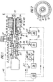
- a pyrometer not only must the pyrometer be protected but the sight path into the vessel must be maintained straight, clear and free from all occludions. Therefore, a system of elements like those illustrated in Figure 1 is required.
- Figure 1 shows a portion the vertical wall of a refractory lined vessel or conduit 8 in which a layer of molten material 24 develops on the innermost surface 25 of the lining.
- a pyrometer 1 attached to vessel 8 via flanged nozzle 12 and several of the other elements of the system, receives radiation from the interior 11 of vessel 8 through sight hole 15 formed by the interior of nozzle 12 and a coaxially aligned hole drilled through refractory layers 9 and 10 .
- a sight tube 7 Inserted through the sight hole 15 and flush with the most interior surface 25 of the refractory layers is a sight tube 7 which is made from a refractory metal, such as an alloy of molybdenum having a high recrystallization temperature.
- the sight tube 7 extends through all layers of the refractory lining of the vessel and connects to a sight tube centering ring 6 which is co-axially affixed to the flanged vessel nozzle 12 .
- the sight tube centering ring 6 is constructed like a hollow doughnut, having a smaller, doughnut-shaped internal passage 16 which communicates with a side entry port 17 for connection to a supply of purge gas 26 , such as nitrogen, via line 37 .
- the internal passage 16 also communicates with the annular space 14 formed between the sight hole 15 and the sight tube 7 via several hole 27 which are equally spaced around the circumference of the centering ring.
- the space formed by the purge gas source 26 , the side entry connecting port 17 , the internal passage 16 , the holes 27 and the annular space 14 provides a passage called the secondary purge stream, which provides a means for maintaining either a continuous or an intermittent flow of purge gas over the external surface of the sight tube 7 .
- This secondary purge stream also doubles as an inert gas blanket which is used to protect the molybdenum alloy sight tube 7 in the case where it may be exposed to an oxidizing atmosphere.
- the supply of purge gas 26 is maintained at a pressure 69 kPa to 6.9 MPa (10 to 1000 psi) higher, but preferably 690 kPa to 3.45 MPa (100 to 500 psi) higher, than the pressure in the interior 11 of vessel 8 ; and the flow rate of purge gas is controlled by valve 43 .
- valve 5 Connected to the sight tube centering ring 6 is a valve 5 which can close very rapidly in case of an emergency. It is understood that the valve 5 is constructed in such a way that, when the valve is in the open position, the interior space 18 provides no obstruction to the optical sight path between the interior of the vessel 11 and the pyrometer 1 .
- the actuator 47 of valve 5 is sized so that it can close the valve even if full differential pressure exists between the interior and the outside of the vessel. Closing of the valve 5 can be initiated either manually or by a control system 28 which supervises and controls the performance of the entire system.
- the other side of the valve 5 is connected to a primary purge ring 4 which is in turn connected to a double sight glass spool piece 3 .
- the double sight glass spool piece contains two high pressure sight glasses 21 and 22 which serve to pass thermal radiation from the vessel interior 11 to the pyrometer 1 while at the same time maintaining the pressure integrity of the vessel 8 .
- the two sight glasses 21 and 22 , the spool piece 3 , the primary purge ring 4 , the valve 5 and the sight tube centering ring 6 are all constructed, both separately and as a unit, to be able to withstand the high pressures which may be found inside vessel 8 .
- the sight glasses 21 and 22 themselves may be constructed from any suitable material, such as quartz or sapphire, which has high transmissivity in the appropriate spectral region, as well as the necessary mechanical properties.
- the primary purge ring 4 is constructed like a hollow doughnut, having a smaller, doughnut-shaped internal passage 20 which communicates with a side entry port 19 for connection to a supply of purge gas 29 , such as nitrogen, via line 36 .
- purge gas 29 such as nitrogen
- the source of gas 29 may be the same as the source of gas 26 for the sight tube centering ring 6 ; but it does not have to be.
- the supply of purge gas 29 is maintained at a pressure 69 kPa to 6.9 MPa (10 to 1000 psi) higher, but preferably 690 kPa to 3.45 MPa (100 to 500 psi) higher, than the pressure in the interior 11 of vessel 8 ; and the flow rate of purge gas is controlled by valve 44 .
- the internal passage 20 of the primary purge ring 4 also communicates with the cylindrical space 30 formed along the cylindrical axis of the doughnut-shaped purge ring 4 via several equally spaced holes 31 . These holes are oriented circumferentially around the purge ring and at an angle with respect to the interior face of the primary sight glass 21 .
- the primary purge stream which performs at least two functions.
- the interior face of the primary sight glass 21 is kept cool and optically clean by the sweeping action of the gas as it flows from the holes 31 over the face of the sight glass 21 and then into the space 30 in the interior of the primary purge ring 4 .
- the interior of the sight tube 7 and the sight tube opening 13 are purged and kept open and free of occlusions by the purging action of the gas flowing through the optical passage originating at the interior face of the primary sight glass 21 and continuing through the cylindrical space 30 , the interior space 18 of valve 5 , the interior space 32 of the sight tube centering ring 6 , the interior of the sight tube 7 and the sight tube opening 13 .
- the flow of purge gas in these spaces can be either continuous or intermittent as will be explained later.
- Purge gas exiting both openings 13 and 14 enters vessel interior 11 and mixes with the reaction gases.
- the double sight glass spool piece 3 , the primary purge ring 4 , the valve 5 and the sight tube centering ring 6 are all fitted on each end with ring joint type flanged fittings which tend to automatically align all these elements coaxially with each other.
- the sight tube 7 is constructed so that it is also coaxially aligned with the above mentioned elements.
- the pyrometer 1 is attached to and held in precise optical alignment with the rest of the elements in the system by an optical alignment ring 2 which is also fitted with a ring joint type flanged fitting for connection to the exterior end of the double sight glass spool piece 6 .
- Optical alignment of the pyrometer 1 is accomplished by turning adjustment screws on the optical alignment ring 2 .
- the optical sight path from the pyrometer 1 to the interior 11 of vessel 8 originates at the objective lens of the pyrometer and passes through the optical alignment ring 2 , the two coaxially aligned high pressure sight glasses 21 and 22 of the double sight glass spool piece 3 , the cylindrical space 30 of the interior of the primary purge ring 4 , the interior space 18 of the valve 5 , the cylindrical space 32 of the interior of the sight tube centering ring 6 , the cylindrical interior of the sight tube 7 , and the sight tube opening 13 .
- the system claimed herein provides means to safely isolate the pyrometer 1 and sight glasses 21 and 22 from the vessel 8 in case of an emergency.
- the safety system consists of a means to monitor the condition of both sight glasses as well as a means to take remedial action in the unlikely event that one or both of the sight glasses fails.
- the primary element of the safety system is the double sight glass spool piece 3 .
- the primary sight glass 21 and the secondary sight glass 22 are separated by a small, sealed, gas-tight space 33 which communicates with a side entry port 23 for connection to a high pressure source of gas 34 via line 35 .
- the source of gas 34 may be the same as the gas sources 29 and/or 26 , but need not be. In general, however, the gas from source 34 will be an inert gas.
- the pressure of gas source 34 is controlled in such a way that it is always at a pressure 69 kPa to 3.45 MPa (10 to 500 psi) higher, and preferably 690 kPa to 1.38 MPa (100 to 200 psi) higher, than the pressure in the interior 11 of vessel 8 .
- flow sensor 38 would detect a flow greater than zero in line 35
- pressure sensor 39 would detect a pressure decrease from the set pressure. In such an instance, sensors 38 and 39 would send signals via signal lines 40 and 41 respectively to control system 28 .
- control system 28 Upon receiving a signal from either line 40 or line 41 , or from both, control system 28 causes valve 5 to close via line 42 .
- the safety system also provides a means to determine which one has failed. If the primary sight glass 21 has failed, the pressure in line 35 , as detected by pressure sensor 39 , will decrease by no more than the difference between the pressure of source 34 and the pressure in vessel interior 11 . However, if the secondary sight glass 22 fails, the pressure in line 35 will decrease to a level below the pressure in vessel interior 11 .
- valve 5 closes quickly when the sensors 38 and 39 detect the change in line 35 and activate control system 28 .
- a most important aspect of this invention is the means whereby the various purge gas streams are controlled in order to maintain a clear optical sight path into a vessel containing hot, particle laden gases and having a layer of molten material which tends to run down the vertical wall of the vessel into the opening of the sight tube.
- both solid particles and molten material will tend to enter the sight tube opening 13 causing it to become obstructed and causing the optical sight path to the pyrometer 1 to become occluded.
- the group of elements comprised of the purge gas supply 29 , the control valve 44 , the supply line 36 , the primary purge ring 4 and the open spaces 20 , 31 , 30 , 18 , 32 , and 13 is called the primary purge stream.
- the means provided by this system of elements to remedy the problem just described consists of two steps: first, the accumulated material is allowed to reheat so that it begins to become molten again; and second, the accumulation is forced, or blown, out of the way and into the vessel interior 11 by a high volume impulse of high pressure purge gas directed at the accumulation along the optical sight path as well as through the annular space 14 .
- control system 28 closes valves 5 and 43 via lines 42 and 45 respectively. This action stops the flow of purge gas in both the primary purge stream, i.e. the optical sight path, as well as in the secondary purge stream, i.e. the annular space 14 . It also momentarily interrupts the temperature reading; however, if two identical systems are used on the same vessel, one system can always be measuring temperature while the other one is executing this impulse procedure. Note also that valve 5 is closed, rather than valve 44 , in order to protect the primary sight glass 21 while the primary purge stream is stopped.
- control system 28 After an appropriate amount of time has elapsed, normally between 1 and 60 minutes, but preferably 1 to 15 minutes, control system 28 quickly opens valves 5 , 43 and 44 wide open via lines 42 , 45 and 46 respectively. This high volume flow of gas is maintained for a period of time normally lasting from 1 to 60 seconds, but preferably from 5 to 15 seconds. The pyrometer reading returns to its previous value during this period as the occlusion is blown away. Following this period, control system 28 readjusts the valve positions of valves 43 and 44 to their previous operating positions, and lowers the pressures of gas sources 26 and 29 to their normal levels.
Landscapes
- Physics & Mathematics (AREA)
- General Physics & Mathematics (AREA)
- Spectroscopy & Molecular Physics (AREA)
- Radiation Pyrometers (AREA)
Claims (11)
- Un réacteur pour faire réagir un mélange hydrocarboné dans la chambre de réaction du réacteur pour produire un gaz synthétique et une matière particulaire, ledit réacteur présentant une paroi interne (8), un revêtement féfractaire (9, 10) tout autour de la chambre de réaction, et un orifice perforé (15) qui traverse ledit revêtement à partir d'un orifice dans la paroi du réacteur et qui débouche dans la chambre de réaction, et un assemblage formant tube de visée amovible positionné dans ledit orifice perforé (15) pour permettre un accès visuel à la chambre de réaction pour conduire un rayonnement à partir de celle-ci, l'assemblage formant tube de visée comprenant un élément tubulaire allongé (7) quie définit un passage de visée cylindrique interne quie présente une face et une extrémité intérieure ouverte et une extrémité extérieure ouverte, ledit élément tubulaire allongé (7) étant longitudinalement à fleur dans ledit orifice perforé (15), un premier distributeur toroïdal (6) attaché à ledite extrémité extérieure ouverte dudit élément tubulaire allongé (7) et présentant un orifice d'entrée (17) qui communique avec une source sous pression (26) d'un gaz de purge, et au moins un orifice d'échappement (27), une vanne d'arrêt (5) présentant un orifice d'entrée, attachée audit distributeur (6), qui, une fois ouverte, permet un accès visuel en ligne de visée droite à travers la vanne et l'élément tubulaire allongé et présentant une extrémité extérieure, un second distributeur toroïdal (4) attaché à ladite extrémité extérieure de ladite vanne (5), et présentant un orifice d'entrée (19) qui peut être mis en communication avec une source sous pression (29) de gaz de purge, et au moins un orifice d'échappement (31) qui est relié à un espace axial (30) entouré par le second distributeur toroïdal, ledit espace axialement enfermé (30) étant immédiatemment contigu à l'espace intérieur de la vanne d'arrêt (5) qui, à son tour, est en liaison aven un passage de gaz cylindrique interne défini par l'élément tubulaire (7), et une pièce en forme de bobine (3) qui contient deux vitres de visée alignées de façon coaxiale (21,22), attachées au second distributeur toroïdal (4) et qui, en coopération avec le second distributeur toroïdal (4), la vanne d'arrêt (5), le premier distributeur toroïdal (6), l'élément tubulaire (7), les différentes sources de gaz (26, 29) et les conduites d'alimentation et le réacteur, forment une enceinte étanche au gaz, ladite pièce en forme de bobine (3) comportant une petite enceinte (33) scellée, étanche au gaz entre lesdites deux vitres de visée alignées de façon coaxiale (21,22) où ladite enceinte présente un orifice d'entrée (23) qui peut être mis en communication avec une source sous pression (34) d'un gaz, caractérisé en ce que ledit élément tubulaire allongé (7) est positionné dans ledit orifice perforé (15) pour définir un passage annulaire (14) de gaz de purge entre ledit élément tubulaire (7) et ledit orifice perforé (15), l'orifice d'entrée (27) du premier distributeur toroïdal (6) étant ainsi en communication avec ledit passage annulaire (14) de gaz de purge, la face à l'extrémité intérieure ouverte de l'élément tubulaire allongé (7) est située dans un plan commun avec la paroi (25) de la chambre de réaction, et l'assemblage formant tube de visée amovible comprend un élément d'alignement optique (2) connecté à l'extrémité éloignée de ladite pièce en forme de bobine (3), fournissant un moyen d'attacher et d'aligner optiquement un pyromètre (1) ou n'importe quel autre appareil de ce type de réception de rayonnement dans le but de mesurer le rayonnement émis par la matière gazeuse et particulaire contenue à l'intérieur du réacteur.
- Un dispositif tel que défini dans la revendication 1, caracterisé en ce que ledit élément tubulaire (7), ledit passage cylindrique interne de gaz de purge et ledit passage annulaire de gaz de purge (14) ont une section trasversale de surface substantiellement uniforme dans un plan perpendiculaire à l'axe longitudinal dudit élément tubulaire.
- Un dispositif tel que défini dans la revendication 1 ou dans la revendication 2, ledit élément tubulaire (7) est fabriqué d'un matériau caractérisé par une résistance aux températures élevées et une haute température de recristallisation, et caracterisé en ce que ledit élément tubulaire (7) résistant aux températures élevées est capable de résisteur, sans se déformer, aux forces de cisaillement qui peuvent être exercées sur lui par des couches en mouvement du revêtement réfractaire à l'intérieur du récipient, et caracterisé en ce que ledit élément tubulaire (7) est résistant aux contraintes thermiques qui provoquent l'écaillage et la détérioration.
- Un dispositif tel que défini dans l'une quelconque des revendications 1 à 3, caracterisé en ce que la combinaison d'éléments sont connectés de façon à fournir un chemin de visée amovible, droit, non-obstrué qui s'étend de la surface intérieure (25) de ladite chambre de réaction jusqu'au dispositif (1) attaché de réception de rayonnement, quand ladite vanne d'arrêt (5) est dans sa position normale ouverte.
- Un dispositif tel que défini dans l'une quelconque des revendications 1 - 4, caracterisé en ce que le premier distributeur toroïdal (6), le second distributeur toroïdal (4) et la pièce en forme de bobine à double vitre de visée (3) sont tous connectés à des sources (26, 29, 34) de gaz à des pressions supérieures à la pression régnant à l'intérieur de la chambre de réaction.
- Un dispositif tel que défini dans la revendication 5, caracterisé en ce que il est prévu des moyens (28, 43-46) pour contrôler indépendamment la pression et les débits de gaz de purge respectives qui pénètrent dans les passages internes des premier et second distributeurs toroïdaux (4, 6).
- Un dispositif tel que défini dans la revendication 6, caracterisé en ce que le gaz de purge est un gaz inerte.
- Un dispositif tel que défini dans la revendication 6, caracterisé en ce que le gaz de purge est un gaz de réaction tel qu'un gaz recyclé du réacteur.
- Un dispositif tel que défini dans l'une quelconque des revendications 5 - 8, caracterisé en ce que il est prévu des détecteurs (F, P) pour déceler une augmentation de la pression et/ou la présence d'un courant de gaz dans la petite enceinte (33) scellée et étanche au gaz, entre les deux vitres (21, 22) de visée dans la pièce en forme de bobine (3) et pour actionner automatiquement la vanne d'arrêt (5) pour fermer.
- Un dispositif tel que défini dans l'une quelconque des revendications 1 - 9, caracterisé en ce que à la fois le passage de visée cylindrique dans ledit élément tubulaire (7) et l'espace annulaire (4) extérieur à l'élément tubulaire sont simultanément et continuellement purgés dans le but d'empêcher des particules de pénétrer à l'intérieur de l'élément tubulaire et d'obstruer le chemin de visée.
- Un dispositif tel que défini dans la revendication 3 caracterisé en ce que ledit élément tubulaire (7) est fait d'un alliage de molybdène.
Priority Applications (3)
| Application Number | Priority Date | Filing Date | Title |
|---|---|---|---|
| DK91301514.5T DK0501049T3 (da) | 1991-02-26 | 1991-02-26 | Apparat til måling af temperaturer i procesbeholdere indeholdende et aggressivt miljø |
| EP91301514A EP0501049B1 (fr) | 1991-02-26 | 1991-02-26 | Dispositif de mesure de températures à l'intérieur de récipients de transformation contenant un milieu hostile |
| DE69101970T DE69101970T2 (de) | 1991-02-26 | 1991-02-26 | Vorrichtung zur Messung von Temperaturen innerhalb feindliche Umgebung enthaltenden Verarbeitungsgefässen. |
Applications Claiming Priority (1)
| Application Number | Priority Date | Filing Date | Title |
|---|---|---|---|
| EP91301514A EP0501049B1 (fr) | 1991-02-26 | 1991-02-26 | Dispositif de mesure de températures à l'intérieur de récipients de transformation contenant un milieu hostile |
Publications (2)
| Publication Number | Publication Date |
|---|---|
| EP0501049A1 EP0501049A1 (fr) | 1992-09-02 |
| EP0501049B1 true EP0501049B1 (fr) | 1994-05-11 |
Family
ID=8208201
Family Applications (1)
| Application Number | Title | Priority Date | Filing Date |
|---|---|---|---|
| EP91301514A Expired - Lifetime EP0501049B1 (fr) | 1991-02-26 | 1991-02-26 | Dispositif de mesure de températures à l'intérieur de récipients de transformation contenant un milieu hostile |
Country Status (3)
| Country | Link |
|---|---|
| EP (1) | EP0501049B1 (fr) |
| DE (1) | DE69101970T2 (fr) |
| DK (1) | DK0501049T3 (fr) |
Families Citing this family (2)
| Publication number | Priority date | Publication date | Assignee | Title |
|---|---|---|---|---|
| ES2395984T3 (es) * | 2010-04-26 | 2013-02-18 | Minimax Gmbh & Co Kg | Procedimiento y dispositivo para limpiar una pantalla de inspección de un avisador de incendios |
| GB2527545B (en) | 2014-06-25 | 2018-02-07 | International Moisture Analysers Ltd | Sight glass apparatus |
Family Cites Families (2)
| Publication number | Priority date | Publication date | Assignee | Title |
|---|---|---|---|---|
| DE3104258A1 (de) * | 1981-02-07 | 1982-10-21 | Ruhrchemie Ag, 4200 Oberhausen | Vorrichtung zur messung von temperaturen in druckreaktoren |
| US4411533A (en) * | 1981-04-27 | 1983-10-25 | Texaco Inc. | System for measuring temperature of hot gases laden with entrained solids |
-
1991
- 1991-02-26 DK DK91301514.5T patent/DK0501049T3/da active
- 1991-02-26 DE DE69101970T patent/DE69101970T2/de not_active Expired - Lifetime
- 1991-02-26 EP EP91301514A patent/EP0501049B1/fr not_active Expired - Lifetime
Also Published As
| Publication number | Publication date |
|---|---|
| EP0501049A1 (fr) | 1992-09-02 |
| DE69101970T2 (de) | 1994-08-18 |
| DE69101970D1 (de) | 1994-06-16 |
| DK0501049T3 (da) | 1994-06-13 |
Similar Documents
| Publication | Publication Date | Title |
|---|---|---|
| US5000580A (en) | Apparatus and method for measuring temperatures inside process vessels containing a hostile environment | |
| JP4493842B2 (ja) | 反応器内部の温度を測定する装置 | |
| US4400097A (en) | System for measuring temperatures in pressurized reactors | |
| EP0085143B1 (fr) | Capteur de température à l'infrarouge pour utilisation à haute pression | |
| US4936376A (en) | Synthetic gas cooler with thermal protection | |
| US5233943A (en) | Synthetic gas radiant cooler with internal quenching and purging facilities | |
| CN101772562A (zh) | 立式气化装置 | |
| US5281243A (en) | Temperature monitoring burner means and method | |
| CA2034172C (fr) | Appareil et methode de mesure des temperatures a l'interieur d'enceintes industrielles sous ambiance hostile | |
| EP0501049A1 (fr) | Dispositif de mesure de températures à l'intérieur de récipients de transformation contenant un milieu hostile | |
| EP0348850B1 (fr) | Refroidisseur de gaz de synthèse avec protection thermique | |
| US4685703A (en) | Expansible and contractible duct | |
| US4411533A (en) | System for measuring temperature of hot gases laden with entrained solids | |
| JPH05296845A (ja) | 過酷な内部環境状態の処理容器の内部温度測定装置 | |
| US4385501A (en) | Hot gas cooler | |
| JPH01315490A (ja) | 炭素質燃料混合物をガス化する装置 | |
| CA1304226C (fr) | Systeme de refroidissement de bruleur de gazogene sous pression | |
| US5740197A (en) | Cooled probe for use in high temperature process vessels | |
| ES2247697T3 (es) | Control de flujo de oxigeno para gasificacion. | |
| CN1026614C (zh) | 含有对抗性环镜的处理容器内部温度测定仪 | |
| US4850001A (en) | Orifice blockage detection system | |
| JPH06313540A (ja) | 炉内覗き窓装置 | |
| JPH0543882A (ja) | 石炭ガス化炉炉内監視装置 | |
| CN204389028U (zh) | 气化反应器 | |
| JPS6158114B2 (fr) |
Legal Events
| Date | Code | Title | Description |
|---|---|---|---|
| PUAI | Public reference made under article 153(3) epc to a published international application that has entered the european phase |
Free format text: ORIGINAL CODE: 0009012 |
|
| AK | Designated contracting states |
Kind code of ref document: A1 Designated state(s): DE DK GB IT NL SE |
|
| 17P | Request for examination filed |
Effective date: 19930204 |
|
| 17Q | First examination report despatched |
Effective date: 19930628 |
|
| GRAA | (expected) grant |
Free format text: ORIGINAL CODE: 0009210 |
|
| AK | Designated contracting states |
Kind code of ref document: B1 Designated state(s): DE DK GB IT NL SE |
|
| ITF | It: translation for a ep patent filed | ||
| REG | Reference to a national code |
Ref country code: DK Ref legal event code: T3 |
|
| REF | Corresponds to: |
Ref document number: 69101970 Country of ref document: DE Date of ref document: 19940616 |
|
| EAL | Se: european patent in force in sweden |
Ref document number: 91301514.5 |
|
| PLBE | No opposition filed within time limit |
Free format text: ORIGINAL CODE: 0009261 |
|
| STAA | Information on the status of an ep patent application or granted ep patent |
Free format text: STATUS: NO OPPOSITION FILED WITHIN TIME LIMIT |
|
| 26N | No opposition filed | ||
| REG | Reference to a national code |
Ref country code: GB Ref legal event code: IF02 |
|
| PGFP | Annual fee paid to national office [announced via postgrant information from national office to epo] |
Ref country code: DK Payment date: 20021218 Year of fee payment: 13 |
|
| PGFP | Annual fee paid to national office [announced via postgrant information from national office to epo] |
Ref country code: NL Payment date: 20030110 Year of fee payment: 13 |
|
| PGFP | Annual fee paid to national office [announced via postgrant information from national office to epo] |
Ref country code: SE Payment date: 20030205 Year of fee payment: 13 |
|
| PG25 | Lapsed in a contracting state [announced via postgrant information from national office to epo] |
Ref country code: SE Free format text: LAPSE BECAUSE OF NON-PAYMENT OF DUE FEES Effective date: 20040227 |
|
| PG25 | Lapsed in a contracting state [announced via postgrant information from national office to epo] |
Ref country code: DK Free format text: LAPSE BECAUSE OF NON-PAYMENT OF DUE FEES Effective date: 20040301 |
|
| PG25 | Lapsed in a contracting state [announced via postgrant information from national office to epo] |
Ref country code: NL Free format text: LAPSE BECAUSE OF NON-PAYMENT OF DUE FEES Effective date: 20040901 |
|
| REG | Reference to a national code |
Ref country code: DK Ref legal event code: EBP |
|
| EUG | Se: european patent has lapsed | ||
| NLV4 | Nl: lapsed or anulled due to non-payment of the annual fee |
Effective date: 20040901 |
|
| PG25 | Lapsed in a contracting state [announced via postgrant information from national office to epo] |
Ref country code: IT Free format text: LAPSE BECAUSE OF NON-PAYMENT OF DUE FEES;WARNING: LAPSES OF ITALIAN PATENTS WITH EFFECTIVE DATE BEFORE 2007 MAY HAVE OCCURRED AT ANY TIME BEFORE 2007. THE CORRECT EFFECTIVE DATE MAY BE DIFFERENT FROM THE ONE RECORDED. Effective date: 20050226 |
|
| PGRI | Patent reinstated in contracting state [announced from national office to epo] |
Ref country code: IT Effective date: 20080301 |
|
| PGFP | Annual fee paid to national office [announced via postgrant information from national office to epo] |
Ref country code: IT Payment date: 20100224 Year of fee payment: 20 |
|
| PGFP | Annual fee paid to national office [announced via postgrant information from national office to epo] |
Ref country code: DE Payment date: 20100226 Year of fee payment: 20 Ref country code: GB Payment date: 20100224 Year of fee payment: 20 |
|
| REG | Reference to a national code |
Ref country code: DE Ref legal event code: R071 Ref document number: 69101970 Country of ref document: DE |
|
| REG | Reference to a national code |
Ref country code: GB Ref legal event code: PE20 Expiry date: 20110225 |
|
| PG25 | Lapsed in a contracting state [announced via postgrant information from national office to epo] |
Ref country code: GB Free format text: LAPSE BECAUSE OF EXPIRATION OF PROTECTION Effective date: 20110225 |
|
| PG25 | Lapsed in a contracting state [announced via postgrant information from national office to epo] |
Ref country code: DE Free format text: LAPSE BECAUSE OF EXPIRATION OF PROTECTION Effective date: 20110226 |