EP0501113B1 - Dispositif sans membrane pour la production de chlore gazeux - Google Patents
Dispositif sans membrane pour la production de chlore gazeux Download PDFInfo
- Publication number
- EP0501113B1 EP0501113B1 EP92100391A EP92100391A EP0501113B1 EP 0501113 B1 EP0501113 B1 EP 0501113B1 EP 92100391 A EP92100391 A EP 92100391A EP 92100391 A EP92100391 A EP 92100391A EP 0501113 B1 EP0501113 B1 EP 0501113B1
- Authority
- EP
- European Patent Office
- Prior art keywords
- caustic
- anode
- caustic solution
- solution
- gas
- Prior art date
- Legal status (The legal status is an assumption and is not a legal conclusion. Google has not performed a legal analysis and makes no representation as to the accuracy of the status listed.)
- Expired - Lifetime
Links
Images



Classifications
-
- C—CHEMISTRY; METALLURGY
- C02—TREATMENT OF WATER, WASTE WATER, SEWAGE, OR SLUDGE
- C02F—TREATMENT OF WATER, WASTE WATER, SEWAGE, OR SLUDGE
- C02F1/00—Treatment of water, waste water, or sewage
- C02F1/46—Treatment of water, waste water, or sewage by electrochemical methods
- C02F1/461—Treatment of water, waste water, or sewage by electrochemical methods by electrolysis
- C02F1/467—Treatment of water, waste water, or sewage by electrochemical methods by electrolysis by electrochemical disinfection; by electrooxydation or by electroreduction
- C02F1/4672—Treatment of water, waste water, or sewage by electrochemical methods by electrolysis by electrochemical disinfection; by electrooxydation or by electroreduction by electrooxydation
- C02F1/4674—Treatment of water, waste water, or sewage by electrochemical methods by electrolysis by electrochemical disinfection; by electrooxydation or by electroreduction by electrooxydation with halogen or compound of halogens, e.g. chlorine, bromine
-
- C—CHEMISTRY; METALLURGY
- C25—ELECTROLYTIC OR ELECTROPHORETIC PROCESSES; APPARATUS THEREFOR
- C25B—ELECTROLYTIC OR ELECTROPHORETIC PROCESSES FOR THE PRODUCTION OF COMPOUNDS OR NON-METALS; APPARATUS THEREFOR
- C25B9/00—Cells or assemblies of cells; Constructional parts of cells; Assemblies of constructional parts, e.g. electrode-diaphragm assemblies; Process-related cell features
- C25B9/17—Cells comprising dimensionally-stable non-movable electrodes; Assemblies of constructional parts thereof
Definitions
- This invention relates to chlor-alkali cells. More particularly, it refers to a cell for separating chlorine in gaseous form and sodium from salt without the presence of a membrane between the anolyte and catholyte.
- U. S. Patents 4,363,713 and 4,419,207 describe a halogen generator submerged in water. A space between the anode and cathode is filled with salt. The salt bed and an upward water and brine flow maintains separation between the catholyte and anolyte. The generator must be periodically removed from the water to resupply the salt.
- An apparatus is needed that will furnish a continuous supply of chlorine to a swimming pool as needed without constant manual attention.
- a halogen gas such as chlorine
- My apparatus controls the operating level of a liquid anolyte, catholyte and their interface by a combination of overflow pipe routed to a caustic catchment basin and a hydrometer float, or an electronic sensor designed to activate a water source to permit the addition of water as the caustic concentration increases to an unacceptable level.
- the hydrometer float actuates and positions a plate redirecting a continuous flow of water to the catholyte reservoir.
- the electronic sensor activates a valve to allow water to flow to the catholyte reservoir.
- Salt is stored above the liquid level and is consumed upon demand by the system, thereby providing a constant volume of salt in the liquid portion of the system. Chlorine gas coming off at the anode is carried to a collecting chamber where it is drawn off for use.
- My halogen gas generating apparatus 10 shown in FIG. 1 has a cell 12 containing an anode 14 and a cathode 16 in close vertical proximity to each other.
- a hood 18 is located above the anode 14.
- the hood 18 is integral with a vertically extending gas separator column 20.
- Cathode 16 is located above the lower lip of the hood.
- Column 20 also serves as a brine pump to return depleted brine to the salt bed or brine solution 26.
- a conduit 22 returns weak brine produced at the anode from a bore 21 in a lower portion of the gas separator column 20 to the brine solution 26.
- the description hereinafter refers to chlorine gas produced by this apparatus, but it is understood that other halogen gases can be produced by changing the salt content.
- Chlorine gas 28 bubbles up through the gas separator column 20 to a tube 30 having a gas tight connection 31 to the top 32 of gas separator column 20.
- Tube 30 leads to a catchment basin container 34 where the chlorine gas may mix with liquid caustic 36 overflowing into the catchment basin container 34 from the cell 12.
- the container has a tube 38 which leads to a liquid to be sanitized, such as a swimming pool. Alternatively, tube 38 can lead directly to a tank for storage or direct use of the chlorine gas 28.
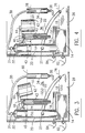
- a hydrometer body 40 is floatably disposed within the caustic 36 and moves in an upward direction as the density of the caustic 36 increases. This upward movement causes plate 41 supported by rod 43 to redirect a water stream from nozzle 46 and allow water to deflect through hole 45 into the caustic 36.
- a float 42 is attached to a plate 44. As the float 42 moves downward in response to decreased caustic level from 80 to 78, the plate 44 moves downwards and allows the water input 46 to be deflected into the caustic 36. Water flows continuously through tubes 67 and 68 when the hydrometer body 40 is in its down position and the plate 44 is in its up position.
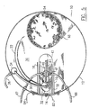
- an electronic control senses cell resistance either through an electrode sensor 88 shown in FIG. 6, located in the wall of cell 12 or increased current through an ampmeter 90.
- a comparator circuit measures the cell resistance and activates a valve 128 to allow water to flow into the caustic 36 through pipe 100 when the caustic concentration increases to an unacceptable level.
- a circuit for the electronic sensor is set forth in FIG. 7. This preferred circuit is connected to the cathode 16 and anode 14 through wires 84 and 82 respectively, with an ampmeter 90 sustaining a voltage drop when the caustic concentration increases.
- a shielded probe 88 mounted in the cell wall 12 warns the circuit if the caustic solution drops below line 78 as shown in FIG. 6. This prevents the system from continuing to operate when danger of explosion is possible.
- Resistors R1, R2, R3 and R4 in the circuit shown in FIG. 7 are selected so non inverting operational amplifier input is high until caustic concentration increases causing voltage drop across ampmeter 90 to increase to the point that minus input becomes higher than plus input.
- the operational amplifier comparator 92 will then switch its output low, turning on the darlington transistor pair 94, allowing current to flow through solenoid valve coil 96 to operate valve 128 and allow water to flow through a pipe 100 into the caustic solution.
- An iron core transformer 102 concentrates magnetic flux from the primary coil 104 for the secondary coil 106.
- a switch 108 activates the power supply and timing circuit R5, R6 and C1 which fires diac 126 activating a light emitting diode 110 in an optical isolator circuit 112A and B, triggering SCR 114 or 116.
- Isolation diodes 118 and 120 prevent the circuit from self-triggering.
- Diodes 122 and 124 act as power rectifiers to power comparator circuit 92 and its bias networks.
- density control could include a manual sampling of the caustic every few hours to determine density and making appropriate water input adjustments.
- a timer control could be used if water input and cell power were held constant.
- a container 48 is vertically disposed in the cell 12 so that its first end 50 is located below the upper level 76 of the brine solution 26.
- the upper level of the brine solution is also the caustic brine interface 76.
- the second end 52 of the container 48 allows for insertion of solid granular salt 54 which is stored within the container 48 and is used gradually upon utilization of the brine.
- An indicator rod 56 protruding through a hole 58 in lid 60 of the container 48 provides a means for visually determining the amount of salt in the container 48.
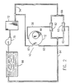
- a completely enclosed system is shown whereby the halogen solution moves through tube 38, through a venturi 62 from whence it is directed through additional tubes 64 to a swimming pool 66.
- the control stream collector line 68 permits the water to return directly to the system via venturi 63 when it is not deflected into the caustic 36.
- a pump 70 moves water from the swimming pool 66, passes it through a standard filter 72, and then to piping 67 back to the cell 12 or through a venturi and pipe 64 back to the pool as seen in FIG. 2.
- An alternate pipe 69 leads to another venturi 63 which directs the flow to pipe 65 back to pipe 64.
- the hydrometer body 40 is seen in more detail in FIGS. 3 and 4.
- the hydrometer is similar to the one set forth in U. S. Patent 4,899,774 and the teaching in that patent is herein incorporated by reference.
- the hydrometer body 40 floats in the caustic solution 36 as seen in FIGS. 3 and 4 in its normal position when there is a preferred caustic density of about 1.01. If the density of the caustic rises above 1.01 it will cause the hydrometer body 40 to rise and cause its circular head plate 41 to block the flow of water through opening 46, thereby causing the water to flow downwardly through opening 45 into the caustic 36 to lower its density.
- float 42 lowers to allow plate 44 to deflect the water flowing through nozzle 46 so that it will flow downwardly into the caustic 36 to raise its level to that seen in FIG. 3, whereupon the plate 44 is raised by float 42 and the water flows through the system out through conduit 68 without entering the cell caustic solution.
- the apparatus described above provides a chlorine gas producing chlor-alkali cell with a current efficiency which approaches the theoretical current requirements of 200 ampere-hour per pound of chlorine gas produced. Electrical current is provided to the system through wires 82 and 84.
- the cell requires no control instrumentation or valves involving routine maintenance adjustment or skill to set up or care for.
- the system is not sensitive to salt purity or contamination, thus making it a practical water purification device in areas where pure salt is not available.
- the salt compartment 48 and caustic cell compartment 12 can be of any desired cross section or configuration.
- the salt 54 flows freely into the caustic chamber lower brine region 26 where it is dissolved and electrically decomposed at the anode 14.
- the chlorine gas 28 produced at the anode 14 rises as it bubbles in the gas catcher 18 or separator column 20.
- the depleted brine is separated and returned to the brine region 26 via conduit 22.
- the salt 54 moves into the brine region 26 by gravity flow from chamber 48.
- the anolyte (brine)-catholyte interface 76 is well defined in this system and appears at its highest level below the bottom of cathode 16.
- the catholyte 36 is maintained above the denser brine under normal steady-state operation.
- the cathode 16 is positioned above the anode plate 14 at a distance of about 0 to 5 cm and preferably about 1 to 2 cm.
- the cathode is made preferably from stainless steel or titanium.
- the anode is made preferably from carbon, graphite, or platinum, or iridium coated titanium.
- the maximum level 80 of caustic is controlled by the upper lip of collector chamber 34.
- the minimum caustic level 78 is controlled by float 42. Mixing of water introduced into the caustic is caused by the stirring action of the hydrogen gas by bubbles formed at the cathode 16.
- Conduit 30 may be directed to a receiving body for the chlorine gas or to the collecting chamber 34 as seen in FIG. 1 so that catholyte, water and gas are mixed and conducted to the point of use.
- a slight vacuum placed at the destination end of conduit 30 will serve to prevent loss of chlorine.
Landscapes
- Chemical & Material Sciences (AREA)
- Organic Chemistry (AREA)
- Engineering & Computer Science (AREA)
- Electrochemistry (AREA)
- Chemical Kinetics & Catalysis (AREA)
- Life Sciences & Earth Sciences (AREA)
- Metallurgy (AREA)
- General Chemical & Material Sciences (AREA)
- Materials Engineering (AREA)
- Hydrology & Water Resources (AREA)
- Environmental & Geological Engineering (AREA)
- Water Supply & Treatment (AREA)
- Electrolytic Production Of Non-Metals, Compounds, Apparatuses Therefor (AREA)
- Treating Waste Gases (AREA)
- Hybrid Cells (AREA)
Claims (19)
- Appareil pour produire électrolytiquement un gaz halogène à partir d'une solution d'eau salée située dans une pile, comprenant
une anode située au-dessous d'une surface supérieure d'un capot, le capot définissant une partie d'une délimitation entre une interface de solution caustique et d'eau salée,
une cathode située à proximité immédiate verticale au-dessus de l'interface de solution caustique et d'eau salée,
le capot pour collecter du gaz halogène disposé sur l'anode, le capot s'étendant vers le haut vers une colonne de séparation de gaz halogène,
un compartiment de stockage de sel ouvert à une première et à une deuxième extrémité, la première extrémité inférieure s'ouvrant à la solution d'eau salée contenue dans la pile, la deuxième extrémité supérieure étant ouverte pour permettra le remplissage du compartiment avec du sel,
un tube étanche aux gaz s'étendant d'une partie supérieure de la colonne de séparation de gaz à un corps de réception du gaz, et
un moyen pour détecter le moment où la densité de la solution caustique dépasse une valeur de densité prédéterminée. - Appareil selon la revendication 1, dans lequel l'halogène est un gaz chlore et le sel est du chlorure de sodium.
- Appareil selon la revendication 2, dans lequel un tube s'étend depuis une partie inférieure de la colonne de séparation de gaz chlore, vers le bas vers la solution d'eau salée, pour faire revenir l'eau salée de faible concentration sur l'anode.
- Appareil pour produire électrolytiquement un gaz halogène depuis une solution d'eau salée située dans une pile, comprenant
une anode située au-dessous d'une interface de solution caustique et de solution d'eau salée,
une cathode située à proximité immédiate verticale au-dessus à la fois de l'anode et de l'interface de solution caustique et de solution d'eau salée,
un capot de collecte de gaz halogène, disposé sur l'anode, le capot s'étendant vers le haut vers une colonne de séparation de gaz halogène,
un compartiment de stockage de sel, ouvert à une première et à une deuxième extrémité, la première extrémité inférieure s'ouvrant à la solution d'eau salée contenue dans la pile, la deuxième extrémité supérieure étant ouverte pour permettre le remplissage du compartiment avec du sel en grains,
un tube s'étendant depuis une partie inférieure de la colonne de séparation de gaz, vers le bas vers la solution d'eau salée, pour ramener de l'eau salée à faible concentration produite sur l'anode,
un tube étanche aux gaz s'étendant depuis une partie supérieure de la colonne de séparation de gaz vers un corps de réception du gaz, et
un moyen pour détecter le moment où la densité du liquide de solution caustique dépasse une valeur de densité prédéterminée. - Appareil selon la revendication 4, dans lequel le moyen pour mesurer la solution caustique est un hydromètre disposé flottant dans la solution caustique, un moyen de déviation d'eau étant fixé à l'hydromètre pour dévier un courant d'eau vers la solution caustique lorsque la densité de la solution caustique dépasse une valeur de densité prédéterminée.
- Appareil selon la revendication 5, dans lequel un flotteur est disposé dans la solution caustique contenue dans la cellule, le flotteur étant fixé à une plaque de pivotement qui recouvre un courant continu d'eau pour dévier l'eau vers la solution caustique, afin d'augmenter le niveau de solution caustique dans la pile lorsque le niveau de solution caustique diminue.
- Appareil selon la revendication 1, dans lequel le.moyen pour mesurer la solution caustique est un capteur électronique.
- Appareil selon la revendication 4, dans lequel le tube étanche aux gaz mène à un réservoir de collecte, dans lequel le gaz halogène peut être mélangé avec le débordement de solution caustique depuis la pile et un conduit est connecté par une première extrémité au fond du réservoir de collecte et, par une deuxième extrémité, à un corps de récipient de liquides, une circulation étant induite par un vide dans le réservoir de collecte.
- Appareil selon la revendication 4, dans lequel le compartiment de stockage de sel contient du chlorure de sodium et le gaz halogène produit est du chlore.
- Appareil selon la revendication 6, dans lequel le compartiment de stockage de sel contient du chlorure de sodium et le gaz halogène produit est du chlore.
- Appareil selon la revendication 4, dans lequel la distance verticale entre l'anode et la cathode est d'à peu près 1 à 2 cm.
- Appareil pour produire électrolytiquement du gaz chlore à partir d'une solution d'eau salée située dans une pile, comprenant
une anode située au-dessous d'une interface de solution caustique et de solution d'eau salée,
une cathode située à proximité immédiate verticale au-dessus a la fois de l'anode et de l'interface de solution caustique et de solution d'eau salée,
un capot de collecte de gaz chlore disposé sur l'anode, le capot étant réalisé d'un seul tenant avec une colonne de séparation de gaz chlore montée verticalement, la cathode disposée à proximité immédiate verticale au-dessus d'une lèvre inférieure du capot,
un compartiment de stockage de sel monté verticalement ouvert à une première et à une deuxième extrémité, la première extrémité inférieure s'ouvrant à la solution d'eau salée au fond de la pile, la deuxième extrémité supérieure étant située au-dessus de la pile pour fournir une ouverture permettant d'ajouter du chlorure de sodium granulaire,
une conduite s'étendant vers le bas depuis un trou ménagé vers le bas dans une paroi de la colonne de séparation, vers une position située au-dessous de l'interface de solution caustique et de solution d'eau salée, pour renvoyer une solution d'eau salée appauvrie faible produite à l'anode vers la solution d'eau salée,
un tube étanche aux gaz s'étendant depuis une partie supérieure de la colonne vers un corps de réception du gaz chlore, et
un moyen pour détecter le moment où la densité de la solution caustique dépasse une densité prédéterminée. - Appareil selon la revendication 12, dans lequel le moyen pour détecter le moment où la densité de la solution caustique dépasse une densité prédéterminée est un hydromètre disposé flottant dans la solution caustique, un moyen de déviation d'eau étant fixé à l'hydromètre pour dévier un courant d'eau vers la solution caustique lorsque la densité de la solution caustique dépasse une densité prédéterminée.
- Appareil selon la revendication 13, dans lequel un flotteur est disposé dans la solution caustique contenue dans la pile, le flotteur étant fixé à une plaque pivotante déviant un courant d'eau vers la solution caustique lorsque le niveau de solution caustique dans la pile descend à un niveau prédéterminé.
- Appareil selon la revendication 12, dans lequel le moyen pour détecter le moment où la densité de la solution caustique dépasse une densité prédéterminée est un capteur électronique.
- Appareil selon la revendication 12, dans lequel la distance verticale entre l'anode et la cathode est d'à peu près 0 à 5 cm.
- Appareil selon la revendication 16, dans lequel la distance verticale entre l'anode et la cathode est d'à peu près 1 à 2 cm.
- Appareil selon la revendication 12, dans lequel l'anode est constituée de titane recouvert de platine.
- Appareil selon la revendication 12, dans lequel l'anode est constituée de graphite.
Applications Claiming Priority (4)
| Application Number | Priority Date | Filing Date | Title |
|---|---|---|---|
| US66292291A | 1991-03-01 | 1991-03-01 | |
| US662922 | 1991-03-01 | ||
| US07/741,631 US5160596A (en) | 1991-03-01 | 1991-08-07 | Membraneless chlorine gas generating apparatus |
| US741631 | 1991-08-07 |
Publications (2)
| Publication Number | Publication Date |
|---|---|
| EP0501113A1 EP0501113A1 (fr) | 1992-09-02 |
| EP0501113B1 true EP0501113B1 (fr) | 1995-08-02 |
Family
ID=27098629
Family Applications (1)
| Application Number | Title | Priority Date | Filing Date |
|---|---|---|---|
| EP92100391A Expired - Lifetime EP0501113B1 (fr) | 1991-03-01 | 1992-01-11 | Dispositif sans membrane pour la production de chlore gazeux |
Country Status (13)
| Country | Link |
|---|---|
| US (1) | US5160596A (fr) |
| EP (1) | EP0501113B1 (fr) |
| AR (1) | AR244812A1 (fr) |
| AT (1) | ATE125886T1 (fr) |
| AU (1) | AU638631B2 (fr) |
| CA (1) | CA2061876C (fr) |
| DE (1) | DE69203748T2 (fr) |
| DK (1) | DK0501113T3 (fr) |
| ES (1) | ES2077255T3 (fr) |
| GR (1) | GR3017800T3 (fr) |
| HK (1) | HK1004004A1 (fr) |
| MX (1) | MX9200835A (fr) |
| NZ (1) | NZ241779A (fr) |
Families Citing this family (8)
| Publication number | Priority date | Publication date | Assignee | Title |
|---|---|---|---|---|
| FR2717169B1 (fr) * | 1994-03-09 | 1996-05-31 | Bj | Dispositif de production de chlore et de traitement d'eau par ce dernier. |
| JP3089465B2 (ja) * | 1996-06-10 | 2000-09-18 | 本田技研工業株式会社 | 電解試験機 |
| US20050231978A1 (en) * | 2004-03-23 | 2005-10-20 | Kvenvold Anthony M | High efficiency low power LED backlighting system for liquid crystal display |
| CN2880854Y (zh) * | 2006-02-06 | 2007-03-21 | 明达塑胶(厦门)有限公司 | 盐电解器 |
| GB2528650A (en) * | 2014-07-16 | 2016-02-03 | Gaffey Technical Services Ltd | An electrochlorination apparatus |
| CN108265313A (zh) * | 2018-03-27 | 2018-07-10 | 浙江长控电气科技有限公司 | 电解装置及用其电解稀食盐水制取酸性和碱性溶液的方法 |
| US11964886B2 (en) * | 2021-06-18 | 2024-04-23 | Robin J. Wagner | Water management system |
| US12110239B2 (en) | 2021-06-18 | 2024-10-08 | Robin J. Wagner | Water management system |
Family Cites Families (21)
| Publication number | Priority date | Publication date | Assignee | Title |
|---|---|---|---|---|
| US1255096A (en) * | 1917-07-26 | 1918-01-29 | George Francois Jaubert | Electrolytic apparatus. |
| US3129162A (en) * | 1962-03-06 | 1964-04-14 | Clyde B Jones | Water conditioning system and metering device therefor |
| AT272216B (de) * | 1965-06-23 | 1969-06-25 | Oskar Ing Pauser | Gerät zur elektrolytischen Herstellung von Chlorgas und Sauerstoff sowie zum Lösen dieser Gase in in Becken befindlichem Wasser, insbesondere Schwimmbeckenwasser |
| US4097356A (en) * | 1977-09-08 | 1978-06-27 | Dow Yates | Chlorine generator |
| US4256551A (en) * | 1978-11-02 | 1981-03-17 | Imperial Chemical Industries Limited | Electrolytic process |
| US4290873A (en) * | 1979-06-25 | 1981-09-22 | Weaver Ron L | Chlorine gas generator apparatus |
| US4248715A (en) * | 1979-11-23 | 1981-02-03 | Olivier Paul D | Electrolytic chlorine generator |
| CA1141331A (fr) * | 1980-01-17 | 1983-02-15 | Jeffery P. Bindon | Generateur d'halogene electrolytique |
| US4361471A (en) * | 1980-06-23 | 1982-11-30 | Kosarek Louis J | Electrolytic swimming pool chlorination |
| US4419207A (en) * | 1981-06-08 | 1983-12-06 | Bindon Jeffrey P | Electrolytic halogen generators |
| IT1155443B (it) * | 1982-12-23 | 1987-01-28 | Zanussi A Spa Industrie | Cella elettrolitica a funzionamento discontinuo automatizzabile per la produzione di acqua di cloro |
| US4472256A (en) * | 1983-07-13 | 1984-09-18 | Hilbig Herbert H | Electrolytic pool chlorinator |
| US4599159A (en) * | 1985-05-28 | 1986-07-08 | Hilbig Herbert H | Electrolytic pool chlorinator having distribution chamber for filling anode and cathode chambers |
| GB8515383D0 (en) * | 1985-06-18 | 1985-07-17 | Ici Plc | Electrochemical cell |
| US4698144A (en) * | 1986-05-15 | 1987-10-06 | The Dow Chemical Company | Apparatus for balancing electrolytic cell gas with circulating electrolyte |
| US4724059A (en) * | 1986-07-11 | 1988-02-09 | Purichlor Technology Ltd. | Automated chlorine generator |
| US4761208A (en) * | 1986-09-29 | 1988-08-02 | Los Alamos Technical Associates, Inc. | Electrolytic method and cell for sterilizing water |
| US4976842A (en) * | 1989-05-01 | 1990-12-11 | Envirodynamics Limited | Oxidant generator |
| US4899774A (en) * | 1989-05-22 | 1990-02-13 | Keller Jr R Davidson | Fluidic density control for chlor alkali cells |
| US5053114A (en) * | 1989-12-07 | 1991-10-01 | Robert Maddock | Chlorinator apparatus |
| US5037519A (en) * | 1990-10-01 | 1991-08-06 | Jay W. Hathcock | Electrolytic chlorine generator |
-
1991
- 1991-08-07 US US07/741,631 patent/US5160596A/en not_active Expired - Lifetime
-
1992
- 1992-01-11 DK DK92100391.9T patent/DK0501113T3/da active
- 1992-01-11 DE DE69203748T patent/DE69203748T2/de not_active Expired - Fee Related
- 1992-01-11 AT AT92100391T patent/ATE125886T1/de not_active IP Right Cessation
- 1992-01-11 ES ES92100391T patent/ES2077255T3/es not_active Expired - Lifetime
- 1992-01-11 EP EP92100391A patent/EP0501113B1/fr not_active Expired - Lifetime
- 1992-02-26 CA CA002061876A patent/CA2061876C/fr not_active Expired - Fee Related
- 1992-02-27 AU AU11300/92A patent/AU638631B2/en not_active Ceased
- 1992-02-27 MX MX9200835A patent/MX9200835A/es unknown
- 1992-02-27 AR AR92321834A patent/AR244812A1/es active
- 1992-02-28 NZ NZ241779A patent/NZ241779A/xx unknown
-
1995
- 1995-10-18 GR GR950402903T patent/GR3017800T3/el unknown
-
1998
- 1998-04-16 HK HK98103202A patent/HK1004004A1/en not_active IP Right Cessation
Also Published As
| Publication number | Publication date |
|---|---|
| AR244812A1 (es) | 1993-11-30 |
| CA2061876C (fr) | 1999-01-05 |
| MX9200835A (es) | 1992-07-01 |
| EP0501113A1 (fr) | 1992-09-02 |
| DK0501113T3 (da) | 1995-11-27 |
| GR3017800T3 (en) | 1996-01-31 |
| ES2077255T3 (es) | 1995-11-16 |
| US5160596A (en) | 1992-11-03 |
| CA2061876A1 (fr) | 1992-09-02 |
| AU638631B2 (en) | 1993-07-01 |
| HK1004004A1 (en) | 1998-11-13 |
| DE69203748T2 (de) | 1996-04-11 |
| NZ241779A (en) | 1993-04-28 |
| DE69203748D1 (de) | 1995-09-07 |
| ATE125886T1 (de) | 1995-08-15 |
| AU1130092A (en) | 1992-09-10 |
Similar Documents
| Publication | Publication Date | Title |
|---|---|---|
| US4136005A (en) | Electrolytic chlorinator | |
| US4290873A (en) | Chlorine gas generator apparatus | |
| US5037519A (en) | Electrolytic chlorine generator | |
| US4613415A (en) | Electrolytic chlorine and alkali generator for swimming pools and method | |
| CA1141331A (fr) | Generateur d'halogene electrolytique | |
| US4113601A (en) | Water decomposing apparatus | |
| US5795459A (en) | Apparatus and method for water purification | |
| US4808290A (en) | Electrolytic pool chlorinator having baffled cathode chamber into which chlorinated water is delivered | |
| US4781810A (en) | Advanced chlorine generating system | |
| GB2046308A (en) | Electrolytic chlorine purification of water | |
| US5160596A (en) | Membraneless chlorine gas generating apparatus | |
| US5221451A (en) | Automatic chlorinating apparatus | |
| US3767557A (en) | Chlorinator including means to feed an electrolyte of predetermined density and means to withdraw chlorine against a varying back pressure | |
| HK1004004B (en) | Membraneless chlorine gas generating apparatus | |
| US4419207A (en) | Electrolytic halogen generators | |
| EP0589705B1 (fr) | Appareil et procédé pour fournir de l'anhydride carbonique dissout | |
| JPH08165600A (ja) | ステンレス容器の内面研磨方法および装置 | |
| US813844A (en) | Electrolytic apparatus. | |
| RU2456378C1 (ru) | Устройство для получения водорода и кислорода | |
| KR790001478B1 (ko) | 수형 격막식 식염 전해 장치 | |
| CN115161681B (zh) | 一种纯水电解制氢装置 | |
| JP2899685B2 (ja) | 水電解を利用した気泡ポンプ装置 | |
| CN211319081U (zh) | 一种镀金槽用补水装置 | |
| KR200432443Y1 (ko) | 차아염소산나트륨 발생장치용 염수 저장조의 소금량표시장치 | |
| SU874763A1 (ru) | Устройство дл прерывани потока электролита в электролизере |
Legal Events
| Date | Code | Title | Description |
|---|---|---|---|
| PUAI | Public reference made under article 153(3) epc to a published international application that has entered the european phase |
Free format text: ORIGINAL CODE: 0009012 |
|
| AK | Designated contracting states |
Kind code of ref document: A1 Designated state(s): AT BE CH DE DK ES FR GB GR IT LI LU NL SE |
|
| 17P | Request for examination filed |
Effective date: 19921002 |
|
| 17Q | First examination report despatched |
Effective date: 19941024 |
|
| GRAA | (expected) grant |
Free format text: ORIGINAL CODE: 0009210 |
|
| AK | Designated contracting states |
Kind code of ref document: B1 Designated state(s): AT BE CH DE DK ES FR GB GR IT LI LU NL SE |
|
| REF | Corresponds to: |
Ref document number: 125886 Country of ref document: AT Date of ref document: 19950815 Kind code of ref document: T |
|
| REF | Corresponds to: |
Ref document number: 69203748 Country of ref document: DE Date of ref document: 19950907 |
|
| ITF | It: translation for a ep patent filed | ||
| REG | Reference to a national code |
Ref country code: ES Ref legal event code: FG2A Ref document number: 2077255 Country of ref document: ES Kind code of ref document: T3 |
|
| ET | Fr: translation filed | ||
| REG | Reference to a national code |
Ref country code: DK Ref legal event code: T3 |
|
| REG | Reference to a national code |
Ref country code: GR Ref legal event code: FG4A Free format text: 3017800 |
|
| PLBE | No opposition filed within time limit |
Free format text: ORIGINAL CODE: 0009261 |
|
| STAA | Information on the status of an ep patent application or granted ep patent |
Free format text: STATUS: NO OPPOSITION FILED WITHIN TIME LIMIT |
|
| 26N | No opposition filed | ||
| REG | Reference to a national code |
Ref country code: GB Ref legal event code: IF02 |
|
| PGFP | Annual fee paid to national office [announced via postgrant information from national office to epo] |
Ref country code: GB Payment date: 20020115 Year of fee payment: 11 |
|
| PGFP | Annual fee paid to national office [announced via postgrant information from national office to epo] |
Ref country code: DK Payment date: 20020116 Year of fee payment: 11 |
|
| PGFP | Annual fee paid to national office [announced via postgrant information from national office to epo] |
Ref country code: SE Payment date: 20020117 Year of fee payment: 11 Ref country code: CH Payment date: 20020117 Year of fee payment: 11 |
|
| PGFP | Annual fee paid to national office [announced via postgrant information from national office to epo] |
Ref country code: NL Payment date: 20020121 Year of fee payment: 11 |
|
| PGFP | Annual fee paid to national office [announced via postgrant information from national office to epo] |
Ref country code: AT Payment date: 20020124 Year of fee payment: 11 |
|
| PGFP | Annual fee paid to national office [announced via postgrant information from national office to epo] |
Ref country code: LU Payment date: 20020128 Year of fee payment: 11 |
|
| PGFP | Annual fee paid to national office [announced via postgrant information from national office to epo] |
Ref country code: ES Payment date: 20020130 Year of fee payment: 11 |
|
| PGFP | Annual fee paid to national office [announced via postgrant information from national office to epo] |
Ref country code: GR Payment date: 20020131 Year of fee payment: 11 |
|
| PGFP | Annual fee paid to national office [announced via postgrant information from national office to epo] |
Ref country code: BE Payment date: 20020227 Year of fee payment: 11 |
|
| PGFP | Annual fee paid to national office [announced via postgrant information from national office to epo] |
Ref country code: DE Payment date: 20020309 Year of fee payment: 11 |
|
| PG25 | Lapsed in a contracting state [announced via postgrant information from national office to epo] |
Ref country code: LU Free format text: LAPSE BECAUSE OF NON-PAYMENT OF DUE FEES Effective date: 20030111 Ref country code: GB Free format text: LAPSE BECAUSE OF NON-PAYMENT OF DUE FEES Effective date: 20030111 Ref country code: AT Free format text: LAPSE BECAUSE OF NON-PAYMENT OF DUE FEES Effective date: 20030111 |
|
| PG25 | Lapsed in a contracting state [announced via postgrant information from national office to epo] |
Ref country code: SE Free format text: LAPSE BECAUSE OF NON-PAYMENT OF DUE FEES Effective date: 20030112 |
|
| PG25 | Lapsed in a contracting state [announced via postgrant information from national office to epo] |
Ref country code: ES Free format text: LAPSE BECAUSE OF NON-PAYMENT OF DUE FEES Effective date: 20030113 |
|
| PG25 | Lapsed in a contracting state [announced via postgrant information from national office to epo] |
Ref country code: BE Free format text: LAPSE BECAUSE OF NON-PAYMENT OF DUE FEES Effective date: 20030131 Ref country code: CH Free format text: LAPSE BECAUSE OF NON-PAYMENT OF DUE FEES Effective date: 20030131 Ref country code: DK Free format text: LAPSE BECAUSE OF NON-PAYMENT OF DUE FEES Effective date: 20030131 Ref country code: LI Free format text: LAPSE BECAUSE OF NON-PAYMENT OF DUE FEES Effective date: 20030131 |
|
| PG25 | Lapsed in a contracting state [announced via postgrant information from national office to epo] |
Ref country code: NL Free format text: LAPSE BECAUSE OF NON-PAYMENT OF DUE FEES Effective date: 20030801 Ref country code: DE Free format text: LAPSE BECAUSE OF NON-PAYMENT OF DUE FEES Effective date: 20030801 |
|
| PG25 | Lapsed in a contracting state [announced via postgrant information from national office to epo] |
Ref country code: GR Free format text: LAPSE BECAUSE OF NON-PAYMENT OF DUE FEES Effective date: 20030804 |
|
| EUG | Se: european patent has lapsed | ||
| GBPC | Gb: european patent ceased through non-payment of renewal fee | ||
| REG | Reference to a national code |
Ref country code: CH Ref legal event code: PL |
|
| REG | Reference to a national code |
Ref country code: DK Ref legal event code: EBP |
|
| NLV4 | Nl: lapsed or anulled due to non-payment of the annual fee |
Effective date: 20030801 |
|
| REG | Reference to a national code |
Ref country code: FR Ref legal event code: TP |
|
| REG | Reference to a national code |
Ref country code: ES Ref legal event code: FD2A Effective date: 20030113 |
|
| PG25 | Lapsed in a contracting state [announced via postgrant information from national office to epo] |
Ref country code: IT Free format text: LAPSE BECAUSE OF NON-PAYMENT OF DUE FEES;WARNING: LAPSES OF ITALIAN PATENTS WITH EFFECTIVE DATE BEFORE 2007 MAY HAVE OCCURRED AT ANY TIME BEFORE 2007. THE CORRECT EFFECTIVE DATE MAY BE DIFFERENT FROM THE ONE RECORDED. Effective date: 20050111 |
|
| PGFP | Annual fee paid to national office [announced via postgrant information from national office to epo] |
Ref country code: FR Payment date: 20080111 Year of fee payment: 17 |
|
| REG | Reference to a national code |
Ref country code: FR Ref legal event code: ST Effective date: 20091030 |
|
| PG25 | Lapsed in a contracting state [announced via postgrant information from national office to epo] |
Ref country code: FR Free format text: LAPSE BECAUSE OF NON-PAYMENT OF DUE FEES Effective date: 20090202 |