EP0501145A1 - Leckagefreie Durchführung - Google Patents
Leckagefreie Durchführung Download PDFInfo
- Publication number
- EP0501145A1 EP0501145A1 EP19920101219 EP92101219A EP0501145A1 EP 0501145 A1 EP0501145 A1 EP 0501145A1 EP 19920101219 EP19920101219 EP 19920101219 EP 92101219 A EP92101219 A EP 92101219A EP 0501145 A1 EP0501145 A1 EP 0501145A1
- Authority
- EP
- European Patent Office
- Prior art keywords
- bellows
- leakage
- valve body
- free
- implementation according
- Prior art date
- Legal status (The legal status is an assumption and is not a legal conclusion. Google has not performed a legal analysis and makes no representation as to the accuracy of the status listed.)
- Granted
Links
Images
Classifications
-
- F—MECHANICAL ENGINEERING; LIGHTING; HEATING; WEAPONS; BLASTING
- F16—ENGINEERING ELEMENTS AND UNITS; GENERAL MEASURES FOR PRODUCING AND MAINTAINING EFFECTIVE FUNCTIONING OF MACHINES OR INSTALLATIONS; THERMAL INSULATION IN GENERAL
- F16K—VALVES; TAPS; COCKS; ACTUATING-FLOATS; DEVICES FOR VENTING OR AERATING
- F16K51/00—Other details not peculiar to particular types of valves or cut-off apparatus
- F16K51/02—Other details not peculiar to particular types of valves or cut-off apparatus specially adapted for high-vacuum installations
-
- F—MECHANICAL ENGINEERING; LIGHTING; HEATING; WEAPONS; BLASTING
- F16—ENGINEERING ELEMENTS AND UNITS; GENERAL MEASURES FOR PRODUCING AND MAINTAINING EFFECTIVE FUNCTIONING OF MACHINES OR INSTALLATIONS; THERMAL INSULATION IN GENERAL
- F16K—VALVES; TAPS; COCKS; ACTUATING-FLOATS; DEVICES FOR VENTING OR AERATING
- F16K41/00—Spindle sealings
- F16K41/10—Spindle sealings with diaphragm, e.g. shaped as bellows or tube
Definitions
- the invention relates to a leak-free implementation on fittings, in particular on vacuum-tight valves made of a flexible bellows, a movable sealing element and a fixed sealing seat.
- Leak-free valves and rotary unions have been used in vacuum technology for a long time.
- Such valves consist, for example, of a movable metal bellows which is stretched or stretched in its axial direction by screwing or tilting devices in such a way that a movable sealing element lifts off from a fixed sealing seat or is pressed onto it.
- Valves based on this principle are common in vacuum technology as well as in valves in the overpressure range.
- Vacuum-tight bushings are also known which take advantage of angular movement of the bellows. Devices of this type require an even higher production outlay, since the angular movement must be supported via at least one axis of rotation.
- the object of the present invention is a leak-free passage through a valve body, which opens and closing or keeping closed and keeping open a flow-pressurized line guaranteed.
- the device should be simple to use, inexpensive to manufacture and, moreover, suitable for both negative and positive pressure systems.
- the pressure drop for the flowing medium must also be reduced to a minimum.
- bellows material in particular its spring rate of the ratio of bellows diameter to bellows length in the range from 0.5 to 2, a safe opening and closing of a valve can be achieved.
- the device according to the invention also makes it possible to carry out a change in length or angle in any plane without further supporting or deflecting devices.
- the angular bellows movement takes place in one plane.
- the movable bellows end is deflected out of the normal plane, for example to enable it to be locked in any position.
- the restoring force or tensile force can be freely selected in a wide range.
- the manufacture of the implementation according to the invention includes only two soldering or welding processes.
- one end of the bellows has to be applied leak-tight on the valve body, on the other hand, the free one Bellows, for example with a plate which contains a transmission pin preferably in the axial direction of bellows.
- the free bellows end can be arranged both inside and outside of the valve body.
- the pipe flow is not or only insignificantly impaired by the transmission means.
- the leak-free implementation in vacuum systems is particularly advantageous, in particular in sorption systems in which cold or superheated water vapor is to be shut off.
- high flow cross sections with the lowest possible flow resistance are required. Since these are often hermetically sealed devices, a high level of leak protection is desirable.
- the transmission means can also actuate the sealing element safely over a relatively long distance. This makes it possible to install the temperature-sensitive seal in temperature-protected system areas, while the bellows and the actuating elements are located in areas that are more accessible but hot.
- the position of the transmission means can be fixed in any position.
- the spring action of the bellows can be used in a more or less axial direction in order to fix locking means in certain positions.
- the bellows is not just angularly deflected, but also more or less axially stretched or stretched.
- the transmission means can be formed inexpensively from pieces of wire, for example. If the wire is made of resilient material, a valve closed with it can also work as a check valve at the same time.
- the leakage-free implementation according to the invention is particularly suitable in sorption apparatuses which operate on the basic principle of the adsorption and desorption reaction, since in these cases a flow of working fluid must be completely shut off in one direction of flow, but in the opposite direction, for safety reasons, it can also be opened in the opposite direction even when the valve is closed have to be.
- a valve can be constructed that closes absolutely tight in one direction of flow, while it also acts as a spring-loaded check valve in the opposite direction, even when closed.
- Metal bellows are known for example from paperback no. 441 from Witzenmann GmbH, Pforzheim. Accordingly, there are a variety of application areas, material criteria, elastic properties and load cycle combinations. Bellows made of stainless steel, brass and bronze have proven particularly successful. But plastic or rubber bellows can also be used advantageously for applications outside of high vacuum technology.
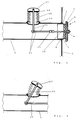
- Fig. 1 shows a valve body 1 in tubular form, which is soldered into a side part 2 of a container.
- the right end of the valve body 1 is designed as a sealing seat 3.
- a movable sealing element 4 is guided within this sealing seat.
- This consists of a seal 5, a pressure plate 6 and a guide cylinder 7. This is provided with holes 8 in the flow area.
- a medium flows out of the container into the valve body 1 through these bores 8.
- the guide cylinder 7, seal 5 and pressure plate 6 are screwed together by means of a nut 9 and a threaded pin 10.
- the setscrew 10 is flexibly connected to a transmission means 12 via a cardan connection 11.
- the transmission means 12 consist of pieces of wire which are connected via eyelets 13.
- One end of the transmission means 12 is non-positively and vacuum-tightly connected to a closure plate 14.
- the closure plate 14 itself is soldered to the movable end of the bellows 15.
- the second end of the bellows 15 is soldered to the valve body 1 using a solder support ring 16.
- An actuating knob 17 is attached to the side of the closure plate 14 facing the bellows. To actuate the leak-free implementation, the actuation knob 17 is actuated manually in the angular bellows direction.
- FIG. 2 shows the device according to FIG. 1 in a changed position.
- a left movement is caused within the valve body 1 on the transmission means 12 in accordance with the bellows properties.
- This deflection is transferred to the sealing element 4 shown in FIG. 1.
- the seal 5 is pressed onto the sealing seat 4.
- the valve shown is closed in this position.
- To open the operating knob 17 must be pushed to the left into the zero position shown in FIG. 1. An actuation of the actuation knob 17 beyond this zero position would lead to a further opening of the sealing element 4.
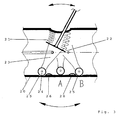
- a bellows 21 is soldered into a cylindrical tube 20, also shown in section, perpendicular to the tube axis.
- the movable end of the bellows 21 projects into the interior of the tube 20.
- a closure plate 22 closes off the movable end of the hose and transmits the angular rotary movement to a locking plate 23, which rests on the inside of the tube via rollers 24. With angular tilting movements of the bellows, this roller 24 runs along the inside of the tube to the left.
- Fig. 3 two further positions A and B of these roles are indicated.
- the inside of the tube is provided with depressions 25 or knobs 26.
- the rollers 24 are pressed into the recesses 25 by the spring force of the bellows and thereby fixed.
- the rollers 24 are lifted when the knobs 26 roll over by compressing the bellows in a more or less axial direction.
Landscapes
- Engineering & Computer Science (AREA)
- General Engineering & Computer Science (AREA)
- Mechanical Engineering (AREA)
- Details Of Valves (AREA)
- Diaphragms And Bellows (AREA)
- Acyclic And Carbocyclic Compounds In Medicinal Compositions (AREA)
- Pharmaceuticals Containing Other Organic And Inorganic Compounds (AREA)
- Transition And Organic Metals Composition Catalysts For Addition Polymerization (AREA)
Abstract
Description
- Die Erfindung betrifft eine leckagefreie Durchführung an Armaturen, insbesondere an vakuumdichten Ventilen aus einem flexiblen Faltenbalg, einem beweglichen Dichtelement und einem feststehenden Dichtsitz.
- In der Vakuumtechnik sind leckagefreie Ventile und Drehdurchführungen seit langem im Einsatz. Derartige Ventile bestehen bespielsweise aus einem beweglichen Metallbalg, welcher durch Schraub- oder Kippvorrichtungen in seiner axialen Richtung so gestreckt oder gedehnt wird, daß sich ein bewegliches Dichtelement von einem feststehenden Dichtsitz abhebt oder auf diesen aufgepreßt wird. Ventile nach diesem Prinzip sind außer in der Vakuumtechnik auch bei Armaturen im Überdruckbereich üblich.
- Nachteilig bei diesen Armaturen ist ein relativ hoher Fertigungsaufwand und der damit verbundene, verglichen mit nicht vakuumdichten Armaturen, hohe Preis. Ein weiterer Nachteil besteht darin, daß die durch die Ventile strömenden Medien innerhalb des Ventilkörpers stark umgelenkt werden müssen. Dadurch entstehen Turbulenzen, die den Strömungswiderstand weiter erhöhen.
- Weiterhin sind vakuumdichte Durchführungen bekannt, welche eine angulare Bewegung des Faltenbalges ausnutzen. Derartige Vorrichtungen bedingen einen noch höheren Fertigungsaufwand, da die angulare Bewegung über mindestens eine Drehachse gestützt werden muß.
- Aufgabe der vorliegenden Erfindung ist eine leckagefreie Durchführung durch einen Armaturenkörper, welche das Öffnen und Schließen bzw. Geschlossenhalten und Offenhalten einer strömungsbeaufschlagten Leitung gewährleistet. Die Vorrichtung soll einfach im Gebrauch, preiswert in der Herstellung sein und darüber hinaus sowohl für Unterdruck als auch für Überdrucksysteme geeignet sein. Der Druckabfall für das strömende Medium muß überdies auf ein Mindestmaß reduziert sein.
- Gelöst wird diese Aufgabe bei einer leckagefreien Durchführung der oben genannten Art durch die kennzeichnenden Merkmale des Anspruchs 1.
- Bei geeigneter Wahl des Balgmaterials, insbesondere dessen Federrate des Verhältnisses von Balgdurchmesser zu Balglänge im Bereich von 0,5 bis 2 kann ein sicheres Öffnen und Schließen eines Ventils erreicht werden.
- Durch die erfindungsgemäße Vorrichtung ist es auch möglich, ohne weitere Stütz- oder Umlenkvorrichtungen eine Längen- bzw. Winkeländerung in beliebiger Ebene durchzuführen. In der Regel wird die angulare Balgbewegung in einer Ebene erfolgen. Besonders vorteilhaft ist es aber, wenn das bewegliche Balgende aus der Normalebene ausgelenkt wird, um beispielsweise eine Arretierung in einer beliebigen Position zu ermöglichen.
- Durch geeignete Wahl der Balgfederrate kann auch die Rückstellkraft bzw. Zugkraft in weiten Bereichen frei gewählt werden.
- Die Fertigung der erfindungsgemäßen Durchführung beinhaltet lediglich zwei Löt- bzw. Schweißvorgänge. Zum einen ist das eine Ende des Balges auf den Armaturenkörper leckagedicht aufzubringen, zum anderen wird das freie Balgende, beispielsweise mit einer Platte verbödet, welche einen Übertragungsstift vorzugsweise in axialer Balgrichtung enthält.
- Prinzipiell läßt sich das freie Balgende sowohl im Innenbereich als auch im Außenbereich des Armaturenkörpers anordnen. Bei einer Anordnung außerhalb des Armaturenkörpers, beispielsweise eines geraden Rohrstückes, wird die Rohrströmung nicht oder nur unwesentlich durch die Übertragungsmittel beeinträchtigt.
- Besonders vorteilhaft eignet sich die leckagefreie Durchführung in Unterdrucksystemen, insbesondere in Sorptionssystemen, bei welchen kalter bzw. überhitzter Wasserdampf abgesperrt werden soll. Bei diesen Anwendungen werden hohe Strömungsquerschnitte mit möglichst geringem Strömungswiderstand benötigt. Da es sich hierbei oft um hermetisch geschlossene Apparaturen handelt, ist eine hohe Leckagesicherheit gewünscht. Die Übertragungsmittel können auch über eine relativ lange Wegdistanz das Dichtelement sicher betätigen. Dadurch ist es möglich, die temperaturempfindliche Dichtung in temperaturgeschützte Anlagenbereiche einzubauen, während der Balg und die Betätigungselemente in leichter zugänglichen, aber heißen Bereichen liegen.
- Durch eine Ergänzung mit dem Prinzip nach bekannter Arretierungsvorrichtungen läßt sich die Position der Übertragungsmittel in jeder beliebigen Lage fixieren. Besonders einfach und vorteilhaft ist es hierzu die Federwirkung des Balges zu nutzen. So läßt sich beispielsweise die Federwirkung des Balges in mehr oder weniger axialer Richtung nutzen, um Arretierungsmittel in bestimmten Positionen zu fixieren. In diesem Fall wird also der Balg nicht nur angular ausgelenkt, sondern auch mehr oder weniger axial gedehnt bzw. gestreckt.
- Die Übertragungsmittel lassen sich kostengünstig beispielsweise aus Drahtstücken formen. Sofern der Draht aus federndem Material aufgebaut ist, kann ein damit geschlossenes Ventil auch zugleich als Rückschlagsventil arbeiten. Besonders in Sorptionsapparaten, welche nach dem Grundprinzip der Adund Desorptionsreaktion arbeiten, ist die erfindungsgemäße leckagefreie Durchführung besonders geeignet, da in diesen Fällen eine Arbeitsmittelströmung in einer Strömungsrichtung vollkommen absperrbar sein muß, in entgegengesetzter Richtung jedoch auch bei geschlossenem Ventil aus Sicherheitsgründen ein Öffnen bei Gegendruck möglich sein muß. In diesem Fall läßt sich also ein Ventil konstruieren, das in einer Strömungsrichtung absolut dicht schließt, während es auch im geschlossenen Zustand in der Gegenrichtung quasi als federbelastetes Rückschlagsventil wirkt.
- Metallbälge sind beispielsweise aus dem Taschenbuch Nr. 441 der Fa. Witzenmann GmbH, Pforzheim, bekannt. Demnach gibt es eine Vielzahl von Anwendungsgebieten, Werkstoffkriterien, Elastizitätseigenschaften und Lastspielkombinationen. Besonders bewährt haben sich Bälge aus Edelstahl, Messing und Bronze. Aber auch Kunststoff- oder Gummibälge sind für Einsatzbereiche außerhalb der Hochvakuumtechnik vorteilhaft einzusetzen.
- In der Zeichnung sind vorteilhafte Ausführungsformen der Erfindung dargestellt. Es zeigen:
- Fig. 1 eine leckagefreie Durchführung in geschnittener Darstellung für einen Ventilkörper,
- Fig. 2 die Durchführung nach Fig. 1 im ausgelenkten Zustand und
- Fig. 3 eine leckagefreie Durchführung mit Arretierungsmitteln.
- Fig. 1 zeigt einen Armaturenkörper 1 in Rohrform, welcher in ein Seitenteil 2 eines Behälters eingelötet ist. Das rechte Ende des Armaturenkörpers 1 ist als Dichtsitz 3 ausgearbeitet. Innerhalb dieses Dichtsitzes ist ein bewegliches Dichtelement 4 geführt. Dieses besteht aus einer Dichtung 5, einer Druckplatte 6 und einem Führungszylinder 7. Dieser ist im Strömungsbereich mit Bohrungen 8 versehen. Im geöffneten Zustand strömt durch diese Bohrungen 8 ein Medium aus dem Behälter in den Armaturenkörper 1. Führungszylinder 7, Dichtung 5 und Druckplatte 6 sind mittels einer Mutter 9 und einem Gewindestift 10 verschraubt. Über eine Kardan-Verbindung 11 ist der Gewindestift 10 mit einem Übertragungsmittel 12 flexibel verbunden. Die Übertragungsmittel 12 bestehen aus Drahtstücken, welche über Ösen 13 in Verbindung stehen. Das eine Ende des Übertragungsmittels 12 ist mit einer Verschlußplatte 14 kraftschlüssig und vakuumdicht verbunden. Die Verschlußplatte 14 selbst ist mit dem beweglichen Ende des Balges 15 verlötet. Das zweite Ende des Balges 15 ist mit dem Armaturenkörper 1 unter Verwendung eines Lötstützringes 16 verlötet. Auf der balgabgewandten Seite der Verschlußplatte 14 ist ein Betätigungsknauf 17 aufgesteckt. Zum Betätigen der leckagefreien Durchführung wird der Betätigungsknauf 17 manuell in angularer Balgrichtung betätigt.
- In Fig. 2 ist die Vorrichtung gemäß Fig. 1 in geänderter Position dargestellt. Durch die Auslenkung des Betätigungsknaufes 17 nach rechts wird auf die Übertragungsmittel 12 entsprechend den Balgeigenschaften eine Linksbewegung innerhalb des Armaturenkörpers 1 hervorgerufen. Diese Auslenkung wird auf das in der Fig. 1 dargestellte Dichtelement 4 übertragen. Dadurch wird die Dichtung 5 auf den Dichtsitz 4 gepreßt. Das dargestellte Ventil ist in dieser Stellung geschlossen. Zum Öffnen muß der Betätigungsknauf 17 nach links in die Nullstellung gemäß Fig. 1 geschoben werden. Eine Betätigung des Betätigungsknaufs 17 über diese Nullstellung hinaus würde zu einer weiteren Öffnung des Dichtelementes 4 führen.
- Fig. 3 zeigt eine weitere Ausgestaltung des Erfindungsgedankens. In ein, ebenfalls im Schnitt dargestelltes zylindrisches Rohr 20 ist senkrecht zur Rohrachse ein Balg 21 eingelötet. Das bewegliche Ende des Balges 21 ragt in dieser Ausführungsform in den Innenraum des Rohres 20. Eine Verschlußplatte 22 schließt das bewegliche Schlauchende ab und überträgt die angulare Drehbewegung an ein Arretierblech 23, welches über Rollen 24 auf der Rohrinnenseite anliegt. Bei angularen Kippbewegungen des Balges läuft diese Rolle 24 entlangt der Rohrinnenseite nach links. In der Fig. 3 sind zwei weitere Stellungen A und B dieser Rollen angedeutet. Die Rohrinnenseite ist mit Vertiefungen 25 oder Noppen 26 versehen. Die Rollen 24 werden durch die Federkraft des Balges in die Vertiefungen 25 eingedrückt und dadurch fixiert. Das Anheben der Rollen 24 beim Überrollen der Noppen 26 erfolgt durch ein Stauchen des Balges in mehr oder minder axialer Richtung.
Claims (8)
- Leckagefreie Durchführung durch einen Armaturenkörper (1) insbesondere bei Vakuumventilen mit einem flexiblen Balg (15),
dadurch gekennzeichnet,
daß der Balg (15) mit seinem einen Ende leckagefrei mit dem Armaturenkörper (1) verbunden und mit seinem anderen Ende in bezug auf seine Körperachse eine angulare Kippbewegung ausführt und daß das so bewegliche Ende leckagedicht verschlossen ist und in seinem äußeren Bereich Mittel aufweist, die es erlauben, den Balg mechanisch auszulenken und in seinem inneren Bereich längs der Balgachse Übertragungsmittel (12) aufweist, welche die äussere mechanische Auslenkung in den Innenraum übertragen. - Leckagefreie Durchführung nach Anspruch 1,
dadurch gekennzeichnet,
daß die Übertragungsmittel (12) auf ein Dichtelement (4) wirken, um dieses auf einen Dichtsitz (3) zu pressen. - Leckagefreie Durchführung nach einem der vorangehenden Ansprüche,
dadurch gekennzeichnet,
daß das bewegliche Balgende in den Innenraum des Armaturenkörpers (1) ragt. - Leckagefreie Durchführung nach einem der vorangehenden Ansprüche,
dadurch gekennzeichnet,
daß das bewegliche Balgende Arretierungsmittel (23, 24) aufweist, die eine Fixierung der Kippdurchführung in bestimmter Position erlauben. - Leckagefreie Durchführung nach Anspruch 4,
dadurch gekennzeichnet,
daß die Arretierungsmittel (23, 24) die Federwirkung des Balges in axialer Richtung bei Druck oder Zug nutzen. - Leckagefreie Durchführung nach einem der vorangehenden Ansprüche,
dadurch gekennzeichnet,
daß das am Armaturenkörper (1) angebrachte Balgende mit dem Armaturenkörper (1) verschweißt oder verlötet ist. - Leckagefreie Durchführung nach einem der vorangehenden Ansprüche,
dadurch gekennzeichnet,
daß die Übertragungsmittel (12) flexibel ausgeführt sind. - Leckagefreie Durchführung nach einem der vorangehenden Ansprüche,
dadurch gekennzeichnet,
daß die Durchführung in Sorptionsapparaten Verwendung findet.
Applications Claiming Priority (2)
| Application Number | Priority Date | Filing Date | Title |
|---|---|---|---|
| DE4105944 | 1991-02-26 | ||
| DE4105944A DE4105944A1 (de) | 1991-02-26 | 1991-02-26 | Leckagefreie durchfuehrung |
Publications (2)
| Publication Number | Publication Date |
|---|---|
| EP0501145A1 true EP0501145A1 (de) | 1992-09-02 |
| EP0501145B1 EP0501145B1 (de) | 1996-08-14 |
Family
ID=6425878
Family Applications (1)
| Application Number | Title | Priority Date | Filing Date |
|---|---|---|---|
| EP92101219A Expired - Lifetime EP0501145B1 (de) | 1991-02-26 | 1992-01-25 | Leckagefreie Durchführung |
Country Status (5)
| Country | Link |
|---|---|
| US (1) | US5197712A (de) |
| EP (1) | EP0501145B1 (de) |
| JP (1) | JPH0560267A (de) |
| AT (1) | ATE141393T1 (de) |
| DE (2) | DE4105944A1 (de) |
Cited By (1)
| Publication number | Priority date | Publication date | Assignee | Title |
|---|---|---|---|---|
| GB2263534A (en) * | 1992-01-27 | 1993-07-28 | Bruker Franzen Analytik Gmbh | Valve for high vacuum analysis equipment |
Families Citing this family (6)
| Publication number | Priority date | Publication date | Assignee | Title |
|---|---|---|---|---|
| FI117063B (fi) * | 2003-06-06 | 2006-05-31 | Outokumpu Oy | Venttiilin tiiviste |
| US8066256B2 (en) * | 2008-02-01 | 2011-11-29 | Danfoss A/S | Valve actuator assembly |
| US8123196B1 (en) * | 2009-10-07 | 2012-02-28 | Chernoff Larry J | Integrated valve system |
| EP2431638B1 (de) * | 2010-09-15 | 2017-02-01 | General Electric Technology GmbH | Abdichtvorrichtung und Verfahren |
| EP3952815B1 (de) | 2019-05-31 | 2025-09-24 | Gobi Technologies Inc. | Wärmeregulierungssystem |
| US20210310711A1 (en) | 2019-05-31 | 2021-10-07 | Gobi Technologies Inc. | Temperature-controlled sorption system |
Citations (2)
| Publication number | Priority date | Publication date | Assignee | Title |
|---|---|---|---|---|
| GB907876A (en) * | 1958-12-19 | 1962-10-10 | Phillips & Rabone Ltd | Improvements relating to control means for valves for hand basins |
| DE2708742A1 (de) * | 1976-03-04 | 1977-09-15 | Finnigan Corp | Vakuumeinrichtung |
Family Cites Families (5)
| Publication number | Priority date | Publication date | Assignee | Title |
|---|---|---|---|---|
| US1624736A (en) * | 1925-02-03 | 1927-04-12 | Gen Electric | Valve |
| US1972815A (en) * | 1928-10-30 | 1934-09-04 | Us Gauge Co | Automatic control device |
| US2417546A (en) * | 1943-08-31 | 1947-03-18 | Liquidometer Corp | Air gun valve mechanism |
| DE924143C (de) * | 1952-08-17 | 1955-02-28 | Kuehnle Ag | Absperrschieber, insbesondere fuer Wetterkanaele |
| DE4012425A1 (de) * | 1990-04-19 | 1991-10-24 | Schuth Horst | Schwenkantrieb mit integrierter hermetischer abdichtung fuer spindeldurchfuehrungen |
-
1991
- 1991-02-26 DE DE4105944A patent/DE4105944A1/de not_active Withdrawn
-
1992
- 1992-01-25 EP EP92101219A patent/EP0501145B1/de not_active Expired - Lifetime
- 1992-01-25 AT AT92101219T patent/ATE141393T1/de not_active IP Right Cessation
- 1992-01-25 DE DE59206880T patent/DE59206880D1/de not_active Expired - Lifetime
- 1992-02-13 US US07/834,937 patent/US5197712A/en not_active Expired - Fee Related
- 1992-02-24 JP JP4036141A patent/JPH0560267A/ja active Pending
Patent Citations (2)
| Publication number | Priority date | Publication date | Assignee | Title |
|---|---|---|---|---|
| GB907876A (en) * | 1958-12-19 | 1962-10-10 | Phillips & Rabone Ltd | Improvements relating to control means for valves for hand basins |
| DE2708742A1 (de) * | 1976-03-04 | 1977-09-15 | Finnigan Corp | Vakuumeinrichtung |
Non-Patent Citations (1)
| Title |
|---|
| WO-A- 91/16 563 (SCHUTH) * |
Cited By (2)
| Publication number | Priority date | Publication date | Assignee | Title |
|---|---|---|---|---|
| GB2263534A (en) * | 1992-01-27 | 1993-07-28 | Bruker Franzen Analytik Gmbh | Valve for high vacuum analysis equipment |
| GB2263534B (en) * | 1992-01-27 | 1995-05-17 | Bruker Franzen Analytik Gmbh | Inlet valve for a high-vacuum analyzer |
Also Published As
| Publication number | Publication date |
|---|---|
| US5197712A (en) | 1993-03-30 |
| DE4105944A1 (de) | 1992-08-27 |
| JPH0560267A (ja) | 1993-03-09 |
| DE59206880D1 (de) | 1996-09-19 |
| EP0501145B1 (de) | 1996-08-14 |
| ATE141393T1 (de) | 1996-08-15 |
Similar Documents
| Publication | Publication Date | Title |
|---|---|---|
| EP0763683B1 (de) | Elektromagnetisch betätigbares Ventil | |
| DE2020194A1 (de) | Durchgangsventil mit Stellungsanzeiger | |
| CH688833A5 (de) | Ventil. | |
| WO1998046916A2 (de) | Linearventil | |
| DE4101114C1 (de) | ||
| EP3850198B1 (de) | Ventilvorrichtung | |
| EP0501145B1 (de) | Leckagefreie Durchführung | |
| DE4213957C2 (de) | Stellventil | |
| DE2832801A1 (de) | Betaetigungseinrichtung fuer ein ventil | |
| DE3015830C2 (de) | ||
| DE68917629T2 (de) | Ventil für Fluide. | |
| DE10324874B3 (de) | Ventil, insbesondere Dampfventil | |
| DE60127448T2 (de) | Servogesteuertes sicherheitsventil für behälter für toxische fluide | |
| EP0846904A1 (de) | Ventilanordnung mit direkt betätigtem Ventilkörper | |
| DE102007013505A1 (de) | Armaturenkombination zur Regelung der Durchflussmenge oder des Differenzdruckes | |
| DE1171685B (de) | Klappenventil mit Differentialkolben | |
| AT410360B (de) | Absperrventil | |
| DE3542547A1 (de) | Verstell- bzw. regeleinrichtung | |
| DE3520554C2 (de) | ||
| DE3342945A1 (de) | Absperrvorrichtung fuer einen stroemungskanal | |
| DE19607810A1 (de) | Abgasrückführventil | |
| DE860587C (de) | Absperrhahn fuer Gas-, Dampf- und Fluessigkeitsleitungen | |
| DE2457960A1 (de) | Druckentlasteter schieber | |
| EP2172681A1 (de) | Ventil mit einem drehbaren Verschlussglied | |
| CH252434A (de) | Absperrvorrichtung an einem an einer Hochvakuumpumpe arbeitenden Korpuskularstrahlapparat. |
Legal Events
| Date | Code | Title | Description |
|---|---|---|---|
| PUAI | Public reference made under article 153(3) epc to a published international application that has entered the european phase |
Free format text: ORIGINAL CODE: 0009012 |
|
| AK | Designated contracting states |
Kind code of ref document: A1 Designated state(s): AT BE CH DE ES FR GB IT LI LU NL SE |
|
| 17P | Request for examination filed |
Effective date: 19920922 |
|
| RAP3 | Party data changed (applicant data changed or rights of an application transferred) |
Owner name: ZEO-TECH ZEOLITH TECHNOLOGIE GMBH |
|
| 17Q | First examination report despatched |
Effective date: 19940330 |
|
| GRAH | Despatch of communication of intention to grant a patent |
Free format text: ORIGINAL CODE: EPIDOS IGRA |
|
| GRAA | (expected) grant |
Free format text: ORIGINAL CODE: 0009210 |
|
| AK | Designated contracting states |
Kind code of ref document: B1 Designated state(s): AT BE CH DE ES FR GB IT LI LU NL SE |
|
| PG25 | Lapsed in a contracting state [announced via postgrant information from national office to epo] |
Ref country code: NL Free format text: LAPSE BECAUSE OF FAILURE TO SUBMIT A TRANSLATION OF THE DESCRIPTION OR TO PAY THE FEE WITHIN THE PRESCRIBED TIME-LIMIT Effective date: 19960814 Ref country code: FR Effective date: 19960814 Ref country code: IT Free format text: LAPSE BECAUSE OF FAILURE TO SUBMIT A TRANSLATION OF THE DESCRIPTION OR TO PAY THE FEE WITHIN THE PRESCRIBED TIME-LIMIT;WARNING: LAPSES OF ITALIAN PATENTS WITH EFFECTIVE DATE BEFORE 2007 MAY HAVE OCCURRED AT ANY TIME BEFORE 2007. THE CORRECT EFFECTIVE DATE MAY BE DIFFERENT FROM THE ONE RECORDED. Effective date: 19960814 Ref country code: ES Free format text: THE PATENT HAS BEEN ANNULLED BY A DECISION OF A NATIONAL AUTHORITY Effective date: 19960814 Ref country code: GB Effective date: 19960814 |
|
| REF | Corresponds to: |
Ref document number: 141393 Country of ref document: AT Date of ref document: 19960815 Kind code of ref document: T |
|
| REF | Corresponds to: |
Ref document number: 59206880 Country of ref document: DE Date of ref document: 19960919 |
|
| PG25 | Lapsed in a contracting state [announced via postgrant information from national office to epo] |
Ref country code: SE Effective date: 19961114 |
|
| EN | Fr: translation not filed | ||
| PG25 | Lapsed in a contracting state [announced via postgrant information from national office to epo] |
Ref country code: AT Free format text: LAPSE BECAUSE OF NON-PAYMENT OF DUE FEES Effective date: 19970125 |
|
| PG25 | Lapsed in a contracting state [announced via postgrant information from national office to epo] |
Ref country code: CH Effective date: 19970131 Ref country code: LI Effective date: 19970131 Ref country code: LU Free format text: LAPSE BECAUSE OF NON-PAYMENT OF DUE FEES Effective date: 19970131 Ref country code: BE Effective date: 19970131 |
|
| NLV1 | Nl: lapsed or annulled due to failure to fulfill the requirements of art. 29p and 29m of the patents act | ||
| GBV | Gb: ep patent (uk) treated as always having been void in accordance with gb section 77(7)/1977 [no translation filed] |
Effective date: 19960814 |
|
| PLBE | No opposition filed within time limit |
Free format text: ORIGINAL CODE: 0009261 |
|
| STAA | Information on the status of an ep patent application or granted ep patent |
Free format text: STATUS: NO OPPOSITION FILED WITHIN TIME LIMIT |
|
| 26N | No opposition filed | ||
| REG | Reference to a national code |
Ref country code: CH Ref legal event code: PL |
|
| PGFP | Annual fee paid to national office [announced via postgrant information from national office to epo] |
Ref country code: DE Payment date: 20100728 Year of fee payment: 19 |
|
| REG | Reference to a national code |
Ref country code: DE Ref legal event code: R119 Ref document number: 59206880 Country of ref document: DE Effective date: 20110802 |
|
| PG25 | Lapsed in a contracting state [announced via postgrant information from national office to epo] |
Ref country code: DE Free format text: LAPSE BECAUSE OF NON-PAYMENT OF DUE FEES Effective date: 20110802 |