EP0501198A1 - Durch einen bürstenlosen Gleichstrommotor angetriebenes Gebläse mit einem spiralförmigen Gehäuse - Google Patents
Durch einen bürstenlosen Gleichstrommotor angetriebenes Gebläse mit einem spiralförmigen Gehäuse Download PDFInfo
- Publication number
- EP0501198A1 EP0501198A1 EP92102038A EP92102038A EP0501198A1 EP 0501198 A1 EP0501198 A1 EP 0501198A1 EP 92102038 A EP92102038 A EP 92102038A EP 92102038 A EP92102038 A EP 92102038A EP 0501198 A1 EP0501198 A1 EP 0501198A1
- Authority
- EP
- European Patent Office
- Prior art keywords
- output stage
- housing
- spiral
- stage transistors
- electronics
- Prior art date
- Legal status (The legal status is an assumption and is not a legal conclusion. Google has not performed a legal analysis and makes no representation as to the accuracy of the status listed.)
- Granted
Links
Images


Classifications
-
- F—MECHANICAL ENGINEERING; LIGHTING; HEATING; WEAPONS; BLASTING
- F04—POSITIVE - DISPLACEMENT MACHINES FOR LIQUIDS; PUMPS FOR LIQUIDS OR ELASTIC FLUIDS
- F04D—NON-POSITIVE-DISPLACEMENT PUMPS
- F04D25/00—Pumping installations or systems
- F04D25/02—Units comprising pumps and their driving means
- F04D25/08—Units comprising pumps and their driving means the working fluid being air, e.g. for ventilation
-
- H—ELECTRICITY
- H02—GENERATION; CONVERSION OR DISTRIBUTION OF ELECTRIC POWER
- H02K—DYNAMO-ELECTRIC MACHINES
- H02K29/00—Motors or generators having non-mechanical commutating devices, e.g. discharge tubes or semiconductor devices
- H02K29/06—Motors or generators having non-mechanical commutating devices, e.g. discharge tubes or semiconductor devices with position sensing devices
- H02K29/08—Motors or generators having non-mechanical commutating devices, e.g. discharge tubes or semiconductor devices with position sensing devices using magnetic effect devices, e.g. Hall-plates, magneto-resistors
Definitions
- the invention relates to a blower driven by a brushless DC motor according to the preamble of claim 1.
- junction temperature at the output stage transistors of the control or regulating electronics is a determining factor for the permissible output of a brushless DC motor
- effective cooling of these transistors is of crucial importance. For this reason, it is common to attach the output stage transistors to separate heat sinks. Such heat sinks are expensive and take up a relatively large amount of space.
- the invention has for its object to optimize the heat dissipation from the output stage transistors of the control electronics of the drive motor with a minimum of effort.
- the spiral housing 10 which is designed as a die-cast part and consists, for example, of aluminum, has cooling fins 12 on the inside of the spiral inlet 11 which run parallel to the air flow.
- the control or regulating electronics 13 is arranged on a printed circuit board 14, which are fastened on the outside of the spiral inlet provided with cooling fins 12 by means of spacers 15 made of insulating material (see FIG. 3).
- the electronics 13 containing a capacitor 16 and six output stage transistors 17 (power transistors) in the exemplary embodiment is surrounded by a housing 18, the walls 19, 20 of which are part of the die-cast housing 10.
- the housings of the output stage transistors 17 are releasably attached to the walls 20 of the electronics housing 18 with the interposition of an electrically insulating layer 21 with the aid of a suitable clamp or the like. Holding element and are thus connected to the metallic spiral housing with a positive fit. To improve the heat dissipation, it has proven to be advantageous not to arrange the output stage transistors 17 on a wall or rib of the volute casing, but in groups on different ribs.
- stator of the external rotor motor is designated 22.
- the rotor 24 with the permanent magnets 25 is rotatably mounted on the fixed stator shaft 23 by means of two ball bearings 26.
- a cranked disk 27 is fastened to the rotor 24 and serves as a carrier of the impeller 29 provided with blades 28.
- FIG. 4 a shows, the six required output stage transistors 17 are held side by side on the wall 20 of the electronics housing 18, which is part of the die-cast housing 10.
- the output stage transistors 17 are pressed against the wall 20 of the die-cast or electronics housing by means of two retaining clips 30 and 31.
- three output stage transistors 17 are each attached to a transverse web 32 and 33 of the volute casing 10; in the exemplary embodiment according to FIG. 4 c, the two groups comprise two and one four output stage transistors.
- the part 10 ′ of the spiral housing 10 covering the blades 28 of the impeller 29 is made of plastic in the exemplary embodiment.
- the measure according to the invention reduces the junction temperature at the output stage transistors by approximately 20 to 25 K.
Landscapes
- Engineering & Computer Science (AREA)
- Power Engineering (AREA)
- Mechanical Engineering (AREA)
- General Engineering & Computer Science (AREA)
- Structures Of Non-Positive Displacement Pumps (AREA)
Abstract
Description
- Die Erfindung bezieht sich auf ein durch einen bürstenlosen Gleichstrommotor angetriebenes Gebläse gemäß dem Oberbegriff des Anspruchs 1.
- Da für die zulässige Leistung eines bürstenlosen Gleichstrommotors die Sperrschichttemperatur an den Endstufen-Transistoren der Steuer- oder Regelelektronik einen mitbestimmenden Faktor darstellt, ist eine wirksame Kühlung dieser Transistoren von maßgeblicher Bedeutung. Aus diesem Grund ist es üblich, die Endstufentransistoren an separaten Kühlkörpern zu befestigen. Solche Kühlkörper sind kostenaufwendig und beanspruchen relativ viel Platz.
- Der Erfindung liegt die Aufgabe zugrunde, die Wärmeabfuhr von den Endstufentransistoren der Steuer- bzw. Regelelektronik des Antriebsmotors mit einem Geringstmaß an Aufwand zu optimieren.
- Diese Aufgabe ist erfindungsgemäß mit den Merkmalen im kennzeichnenden Teil des Anspruchs 1 gelöst.
- Durch diese Maßnahme wird eine laminare Durchströmung und demgemäß eine hohe Wärmeübergangszahl erzielt.
- Weiterbildungen und zweckmäßige Ausgestaltungen der Erfindung sind in den Unteransprüchen angegeben.
- Eine bevorzugte Ausführungsform der Erfindung wird im nachstehenden anhand der Zeichnung erläutert.
- Es zeigen:
- Fig. 1
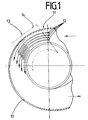
- eine Ansicht des Spiralgehäuses des Gebläses von innen,
- Fig. 2
- eine Ansicht des Spiralgehäuses von außen,
- Fig. 3
- eine Ansicht entlang des Schnittes A-A durch Figur 2,
- Fig. 4a-Fig. 4b
- verschiedene Anordnungen der Endstufentransistoren.
- Wie aus den Figuren 1 bis 3 ersichtlich ist, weist das als Druckgußteil ausgebildete, beispielsweise aus Aluminium bestehende Spiralgehäuse 10 an der Innenseite des Spiraleinlaufs 11 parallel zum Luftstrom verlaufende Kühlrippen 12 auf. Die Steuer- bzw. Regelelektronik 13 ist auf einer Leiterplatte 14 angeordnet, die auf der Außenseite des mit Kühlrippen 12 versehenen Spiraleinlaufs mittels Distanzstücke 15 aus Isoliermaterial befestigt sind (siehe Fig. 3). Die beim Ausführungsbeispiel einen Kondensator 16 und sechs Endstufentransistoren 17 (Leistungstransistoren) enthaltende Elektronik 13 ist von einem Gehäuse 18 umgeben, dessen Wände 19,20 Bestandteil des Druckgußgehäuses 10 sind.
- Die Gehäuse der Endstufentransistoren 17 sind unter Zwischenlage einer elekrisch isolierenden Schicht 21 mit Hilfe einer geeigneten Klammer oder dgl. Halteelement lösbar an den Wandungen 20 des Elektronikgehäuses 18 befestigt und damit wärmeschlüssig mit dem metallischen Spiralgehäuse verbunden. Zur Verbesserung der Wärmeabfuhr hat es sich als vorteilhaft erwiesen, die Endstufentransistoren 17 nicht an einer Wandung bzw. Rippe des Spiralgehäuses anzuordnen, sondern gruppenweise an verschiedenen Rippen.
- In Figur 3 ist der Stator des Außenläufermotors mit 22 bezeichnet. Auf der feststehenden Statorwelle 23 ist der Rotor 24 mit den Permanentmagneten 25 mittels zweier Kugellager 26 drehbar gelagert. Am Rotor 24 ist eine abgekröpfte Scheibe 27 befestigt, die als Träger des mit Schaufeln 28 versehenen Gebläserads 29 dient.
- Wie Figur 4a zeigt, sind hier die sechs erforderlichen Endstufentransistoren 17 nebeneinander an der Wandung 20 des Elektronikgehäuses 18, das Bestandteil des Druckgußgehäuses 10 ist, gehalten. Die Endstufentransistoren 17 sind dabei mittels zweier Halteklammern 30 und 31 an die Wandung 20 des Druckguß- bzw. Elektronikgehäuses angepreßt.
- Im Falle der Fig. 4 b sind je drei Endstufentransistoren 17 an je einem Quersteg 32 und 33 des Spiralgehäuses 10 angebracht, beim Ausführungsbeispiel nach Fig. 4c umfassen die beiden Gruppen einmal zwei und einem vier Endstufentransistoren.
- Der die Schaufeln 28 des Gebläserads 29 abdeckende Teil 10' des Spiralgehäuses 10 besteht beim Ausführungsbeispiel aus Kunststoff.
- Es hat sich gezeigt, daß mit der erfindungsgemäßen Maßnahme eine Reduzierung der Sperrschichttemperatur an den Endstufentransistoren um ca. 20 bis 25 K erreicht wird.
Claims (4)
- Durch einen bürstenlosen Gleichstrommotor angetriebenes Gebläse mit einem spiralförmigen Gehäuse und mit an Kühlkörpern angebrachten Endstufentransistoren der Steuer- bzw. Regelelektronik für den Antriebsmotor, dadurch gekennzeichnet daß das Spiralgehäuse (10) wenigstens im Bereich des Spiraleinlaufs metallisch ausgebildet ist, in diesem Bereich an seiner Innenseite mit parallel zum Luftstrom verlaufenden Kühlrippen (12) versehen ist und daß das die Steuer- bzw. Regelelektronik (13) aufnehmende Gehäuse (18) in wärmeschlüssiger Verbindung mit dem die Kühlrippen (12) enthaltenden Teil des Spiralgehäuses (10) steht.
- Gebläse nach Anspruch 1, dadurch gekennzeichnet, daß die Wände (19,20) des Elektronikgehäuses (18) Bestandteil des metallischen Spiralgehäuses (10) sind.
- Gebläse nach Anspruch 1 oder 2, dadurch gekennzeichnet, daß die Gehäuse der Endstufentransistoren (17) unter Zwischenlage einer elektrisch isolierenden Schicht (21) an die Wandung (20) des Elektronikgehäuses (18) angeklammert sind.
- Gebläse nach Anspruch 1 oder 2, dadurch gekennzeichnet, daß die Endstufentransistoren (17) gruppenweise an quer zur Wandung (20) des Elektronikgehäuses verlaufenden metallischen Stegen (32,33) wärmeschlüssig gehalten sind.
Applications Claiming Priority (2)
| Application Number | Priority Date | Filing Date | Title |
|---|---|---|---|
| DE4106130A DE4106130A1 (de) | 1991-02-27 | 1991-02-27 | Durch einen buerstenlosen gleichstrommotor angetriebenes geblaese mit einem spiralfoermigen gehaeuse |
| DE4106130 | 1991-02-27 |
Publications (2)
| Publication Number | Publication Date |
|---|---|
| EP0501198A1 true EP0501198A1 (de) | 1992-09-02 |
| EP0501198B1 EP0501198B1 (de) | 1995-08-23 |
Family
ID=6425996
Family Applications (1)
| Application Number | Title | Priority Date | Filing Date |
|---|---|---|---|
| EP92102038A Expired - Lifetime EP0501198B1 (de) | 1991-02-27 | 1992-02-07 | Durch einen bürstenlosen Gleichstrommotor angetriebenes Gebläse mit einem spiralförmigen Gehäuse |
Country Status (2)
| Country | Link |
|---|---|
| EP (1) | EP0501198B1 (de) |
| DE (2) | DE4106130A1 (de) |
Cited By (22)
| Publication number | Priority date | Publication date | Assignee | Title |
|---|---|---|---|---|
| DE4307000A1 (de) * | 1993-03-05 | 1994-09-08 | Siemens Ag | Staubsauger mit einem Sauggebläse |
| EP0652375A1 (de) * | 1993-11-05 | 1995-05-10 | General Motors Corporation | Gebläseeinheit |
| FR2728631A1 (fr) * | 1994-12-22 | 1996-06-28 | Valeo Thermique Habitacle | Ventilateur centrifuge, notamment pour vehicule automobile |
| FR2742813A1 (fr) * | 1995-12-26 | 1997-06-27 | Valeo Climatisation | Ventilateur centrifuge, notamment pour vehicule automobile |
| FR2745441A1 (fr) * | 1996-02-22 | 1997-08-29 | Bosch Gmbh Robert | Moteur de soufflante |
| FR2746864A1 (fr) * | 1996-03-26 | 1997-10-03 | Valeo Climatisation | Ventilateur centrifuge a module de commande integre, notamment pour vehicule automobile |
| FR2757576A1 (fr) * | 1996-12-20 | 1998-06-26 | Valeo Climatisation | Ventilateur centrifuge a trappe, notamment pour vehicule automobile |
| FR2765415A1 (fr) * | 1997-06-26 | 1998-12-31 | Bosch Gmbh Robert | Moteur electrique |
| FR2777608A1 (fr) * | 1998-04-17 | 1999-10-22 | Sagem | Motoventilateur a bloc de commande integre |
| EP1308631A1 (de) * | 2001-11-02 | 2003-05-07 | Valeo Climatisation | Motorlüfter |
| WO2003038285A1 (fr) * | 2001-11-02 | 2003-05-08 | Valeo Climatisation | Groupe moto-ventilateur |
| FR2831931A1 (fr) * | 2001-11-02 | 2003-05-09 | Valeo Climatisation | Groupe moto-ventilateur a support moteur desaxe |
| DE19612679C2 (de) * | 1996-03-29 | 2003-10-30 | Temic Auto Electr Motors Gmbh | Kühlerventilator für Kraftfahrzeuge |
| WO2004013944A1 (de) * | 2002-08-01 | 2004-02-12 | Ebm Werke Gmbh & Co. Kg | Elektromotor mit hoher ip-schutzart |
| WO2009000481A1 (de) * | 2007-06-28 | 2008-12-31 | Ebm-Papst St. Georgen Gmbh & Co. Kg | Lüfter mit einer leiterplatte |
| DE102009054188A1 (de) | 2009-11-23 | 2011-05-26 | Behr Gmbh & Co. Kg | Radiallüftergehäuse |
| WO2012019914A1 (de) * | 2010-08-10 | 2012-02-16 | Behr Gmbh & Co. Kg | Lüfter mit elektronikkühler im luftstrom |
| US20120148393A1 (en) * | 2010-12-14 | 2012-06-14 | Delta Electronics, Inc. | Centrifugal fan |
| FR2980740A1 (fr) * | 2011-10-03 | 2013-04-05 | Valeo Systemes Thermiques | Groupe moto-ventilateur avec un couvercle formant un caisson etanche de protection du moteur et des elements electriques du groupe |
| CN103321927A (zh) * | 2013-07-17 | 2013-09-25 | 李良杰 | 螺旋式无叶冷风扇 |
| CN103321926A (zh) * | 2013-07-11 | 2013-09-25 | 李良杰 | 螺旋式无叶风扇 |
| US20260039167A1 (en) * | 2024-08-02 | 2026-02-05 | Brose Fahrzeugteile SE & Co. Kommanditgesellschaft, Würzburg | Electromotive radiator fan of a motor vehicle and motor support plate assembly for the radiator fan |
Families Citing this family (11)
| Publication number | Priority date | Publication date | Assignee | Title |
|---|---|---|---|---|
| DE4231784A1 (de) * | 1991-06-22 | 1994-03-24 | Teves Gmbh Alfred | Elektromotorisch angetriebene Hydraulikpumpe |
| DE4418000C2 (de) * | 1994-05-21 | 1998-03-19 | Fhp Motors Gmbh | Elektronisch gesteuerter Elektromotor, insbesondere mit einem Lüfterrad zum Ansaugen von Kühlluft für Kraftfahrzeuge |
| DE4440495A1 (de) * | 1994-11-12 | 1996-05-15 | Bosch Gmbh Robert | Elektrisch betriebene Luftgebläseeinheit, insbesondere Sekundärluftgebläseeinheit |
| FR2728116A1 (fr) * | 1994-12-12 | 1996-06-14 | Valeo Thermique Habitacle | Equipement regulateur de puissance pour moteur electrique et ventilateur centrifuge muni d'un tel equipement |
| DE19639098A1 (de) * | 1996-09-24 | 1998-03-26 | Wilo Gmbh | Motorpumpe mit gekühltem Frequenzumformer |
| DE19724332A1 (de) * | 1997-06-10 | 1999-01-07 | Kostal Leopold Gmbh & Co Kg | Elektrische Einrichtung |
| DE10045597C1 (de) * | 2000-09-15 | 2002-01-31 | Buhler Motor Gmbh | Pumpe mit einem elektronisch kommutierten Gleichstrommotor |
| DE10245798B4 (de) * | 2002-10-01 | 2004-08-19 | Robert Bosch Gmbh | Elektrisch betriebener Ladeluftverdichter mit integrierter Luftkühlung |
| DE10259761A1 (de) * | 2002-12-19 | 2004-07-08 | BSH Bosch und Siemens Hausgeräte GmbH | Lüftergehäuse |
| DE102014225577A1 (de) * | 2014-12-11 | 2016-06-16 | Robert Bosch Gmbh | Isolationsplatte für eine elektrische Maschine |
| DE102023212975A1 (de) | 2023-12-19 | 2025-06-26 | Schaeffler Technologies AG & Co. KG | Elektrische Maschine mit Gehäuse und Kühlstruktur, Traktionsantrieb |
Citations (3)
| Publication number | Priority date | Publication date | Assignee | Title |
|---|---|---|---|---|
| DE2165419A1 (de) * | 1971-12-29 | 1973-07-05 | Papst Motoren Kg | Ventilatoreinheit |
| EP0345796A2 (de) * | 1988-06-04 | 1989-12-13 | Licentia Patent-Verwaltungs-GmbH | Durch einen Elektromotor angetriebener Lüfter |
| DE3916791A1 (de) * | 1988-10-28 | 1990-05-10 | Piemontese Radiatori | Geblaese-einbausatz, insbesondere fuer eine kraftwagenheizung |
-
1991
- 1991-02-27 DE DE4106130A patent/DE4106130A1/de not_active Ceased
-
1992
- 1992-02-07 DE DE59203329T patent/DE59203329D1/de not_active Expired - Fee Related
- 1992-02-07 EP EP92102038A patent/EP0501198B1/de not_active Expired - Lifetime
Patent Citations (3)
| Publication number | Priority date | Publication date | Assignee | Title |
|---|---|---|---|---|
| DE2165419A1 (de) * | 1971-12-29 | 1973-07-05 | Papst Motoren Kg | Ventilatoreinheit |
| EP0345796A2 (de) * | 1988-06-04 | 1989-12-13 | Licentia Patent-Verwaltungs-GmbH | Durch einen Elektromotor angetriebener Lüfter |
| DE3916791A1 (de) * | 1988-10-28 | 1990-05-10 | Piemontese Radiatori | Geblaese-einbausatz, insbesondere fuer eine kraftwagenheizung |
Cited By (29)
| Publication number | Priority date | Publication date | Assignee | Title |
|---|---|---|---|---|
| DE4307000A1 (de) * | 1993-03-05 | 1994-09-08 | Siemens Ag | Staubsauger mit einem Sauggebläse |
| EP0652375A1 (de) * | 1993-11-05 | 1995-05-10 | General Motors Corporation | Gebläseeinheit |
| FR2728631A1 (fr) * | 1994-12-22 | 1996-06-28 | Valeo Thermique Habitacle | Ventilateur centrifuge, notamment pour vehicule automobile |
| FR2742813A1 (fr) * | 1995-12-26 | 1997-06-27 | Valeo Climatisation | Ventilateur centrifuge, notamment pour vehicule automobile |
| FR2745441A1 (fr) * | 1996-02-22 | 1997-08-29 | Bosch Gmbh Robert | Moteur de soufflante |
| FR2746864A1 (fr) * | 1996-03-26 | 1997-10-03 | Valeo Climatisation | Ventilateur centrifuge a module de commande integre, notamment pour vehicule automobile |
| US5842840A (en) * | 1996-03-26 | 1998-12-01 | Valeo Climatisation | Centrifugal fan with an integrated control module especially for use in motor vehicles |
| DE19612679C2 (de) * | 1996-03-29 | 2003-10-30 | Temic Auto Electr Motors Gmbh | Kühlerventilator für Kraftfahrzeuge |
| FR2757576A1 (fr) * | 1996-12-20 | 1998-06-26 | Valeo Climatisation | Ventilateur centrifuge a trappe, notamment pour vehicule automobile |
| WO1999000887A1 (de) * | 1997-06-26 | 1999-01-07 | Robert Bosch Gmbh | Elektrischer antriebsmotor |
| US6175171B1 (en) * | 1997-06-26 | 2001-01-16 | Robert Bosch Gmbh | Electric drive motor |
| KR100534189B1 (ko) * | 1997-06-26 | 2005-12-08 | 로베르트 보쉬 게엠베하 | 전기 구동 모터 |
| FR2765415A1 (fr) * | 1997-06-26 | 1998-12-31 | Bosch Gmbh Robert | Moteur electrique |
| FR2777608A1 (fr) * | 1998-04-17 | 1999-10-22 | Sagem | Motoventilateur a bloc de commande integre |
| FR2831929A1 (fr) * | 2001-11-02 | 2003-05-09 | Valeo Climatisation | Groupe moto-ventilateur comportant un radiateur integre |
| FR2831931A1 (fr) * | 2001-11-02 | 2003-05-09 | Valeo Climatisation | Groupe moto-ventilateur a support moteur desaxe |
| WO2003038285A1 (fr) * | 2001-11-02 | 2003-05-08 | Valeo Climatisation | Groupe moto-ventilateur |
| US6754075B2 (en) | 2001-11-02 | 2004-06-22 | Valeo Climatisation | Motor-fan unit particularly for a heating and/or air conditioning apparatus for a motor vehicle |
| EP1308631A1 (de) * | 2001-11-02 | 2003-05-07 | Valeo Climatisation | Motorlüfter |
| WO2004013944A1 (de) * | 2002-08-01 | 2004-02-12 | Ebm Werke Gmbh & Co. Kg | Elektromotor mit hoher ip-schutzart |
| WO2009000481A1 (de) * | 2007-06-28 | 2008-12-31 | Ebm-Papst St. Georgen Gmbh & Co. Kg | Lüfter mit einer leiterplatte |
| DE102009054188A1 (de) | 2009-11-23 | 2011-05-26 | Behr Gmbh & Co. Kg | Radiallüftergehäuse |
| WO2012019914A1 (de) * | 2010-08-10 | 2012-02-16 | Behr Gmbh & Co. Kg | Lüfter mit elektronikkühler im luftstrom |
| US20120148393A1 (en) * | 2010-12-14 | 2012-06-14 | Delta Electronics, Inc. | Centrifugal fan |
| US8967962B2 (en) * | 2010-12-14 | 2015-03-03 | Delta Electronics, Inc. | Centrifugal fan |
| FR2980740A1 (fr) * | 2011-10-03 | 2013-04-05 | Valeo Systemes Thermiques | Groupe moto-ventilateur avec un couvercle formant un caisson etanche de protection du moteur et des elements electriques du groupe |
| CN103321926A (zh) * | 2013-07-11 | 2013-09-25 | 李良杰 | 螺旋式无叶风扇 |
| CN103321927A (zh) * | 2013-07-17 | 2013-09-25 | 李良杰 | 螺旋式无叶冷风扇 |
| US20260039167A1 (en) * | 2024-08-02 | 2026-02-05 | Brose Fahrzeugteile SE & Co. Kommanditgesellschaft, Würzburg | Electromotive radiator fan of a motor vehicle and motor support plate assembly for the radiator fan |
Also Published As
| Publication number | Publication date |
|---|---|
| EP0501198B1 (de) | 1995-08-23 |
| DE59203329D1 (de) | 1995-09-28 |
| DE4106130A1 (de) | 1992-09-03 |
Similar Documents
| Publication | Publication Date | Title |
|---|---|---|
| EP0501198B1 (de) | Durch einen bürstenlosen Gleichstrommotor angetriebenes Gebläse mit einem spiralförmigen Gehäuse | |
| EP1217715B1 (de) | Antriebseinheit für Gebläse in Fahrzeugen | |
| EP0958646B1 (de) | Elektromotor mit vorgeschaltetem frequenzumrichter | |
| DE874442T1 (de) | Elektrischer Motor mit verbesserter Luftstromkühleinrichtung | |
| DE19727165A1 (de) | Elektrischer Antriebsmotor | |
| DE19503521B4 (de) | Lüfter mit einem Lüfterrad | |
| DE19612679C2 (de) | Kühlerventilator für Kraftfahrzeuge | |
| DE2655753B2 (de) | Durchzugsbelüfteter elektrischer Kommutatormotor | |
| DE19812729A1 (de) | Elektromotor, insbesondere mit einem Lüfterrad zur Bildung eines Axial- oder Radiallüfters | |
| DE102007000372A1 (de) | Antriebsvorrichtung für ein Handwerkzeuggerät | |
| EP2118493A1 (de) | Lüfter mit einem sensor | |
| WO1992002116A1 (de) | Elektrisches gerät, insbesondere schalt- und steuergerät für kraftfahrzeuge | |
| DE102004031399A1 (de) | Umrichtermotor | |
| DE19756186C1 (de) | Elektromotorisch angetriebene Pumpe, insbesondere für die Servolenkung eines Kraftfahrzeuges | |
| DE4344054A1 (de) | Regelaggregat für eine Kraftfahrzeug-Klimaanlage | |
| DE2743708A1 (de) | Einrichtung zur ableitung der waerme aus einem hermetisch gekapselten geraet | |
| EP1714375B1 (de) | Bürstensystem für einen elektromotorischen antrieb | |
| EP3719972A1 (de) | Antriebseinheit mit einer kühleinheit | |
| EP1878824B1 (de) | Antriebsvorrichtung für eine Waschmaschine | |
| EP1861912B1 (de) | Gebläseeinheit, insbesondere für einen staubsauger | |
| DE69924514T2 (de) | Bürstenloser motor | |
| WO2013037449A2 (de) | Elektromotorisches pumpenaggregat | |
| DE19606487A1 (de) | Gebläsemotor | |
| DE2125270B2 (de) | Kühleinrichtung einer elektrischen Maschine mit Lagerträgern | |
| DE10130950A1 (de) | Elektromotor |
Legal Events
| Date | Code | Title | Description |
|---|---|---|---|
| PUAI | Public reference made under article 153(3) epc to a published international application that has entered the european phase |
Free format text: ORIGINAL CODE: 0009012 |
|
| AK | Designated contracting states |
Kind code of ref document: A1 Designated state(s): DE ES FR GB IT |
|
| 17P | Request for examination filed |
Effective date: 19930225 |
|
| 17Q | First examination report despatched |
Effective date: 19940511 |
|
| GRAA | (expected) grant |
Free format text: ORIGINAL CODE: 0009210 |
|
| AK | Designated contracting states |
Kind code of ref document: B1 Designated state(s): DE ES FR GB IT |
|
| PG25 | Lapsed in a contracting state [announced via postgrant information from national office to epo] |
Ref country code: IT Free format text: LAPSE BECAUSE OF FAILURE TO SUBMIT A TRANSLATION OF THE DESCRIPTION OR TO PAY THE FEE WITHIN THE PRESCRIBED TIME-LIMIT;WARNING: LAPSES OF ITALIAN PATENTS WITH EFFECTIVE DATE BEFORE 2007 MAY HAVE OCCURRED AT ANY TIME BEFORE 2007. THE CORRECT EFFECTIVE DATE MAY BE DIFFERENT FROM THE ONE RECORDED. Effective date: 19950823 Ref country code: ES Free format text: THE PATENT HAS BEEN ANNULLED BY A DECISION OF A NATIONAL AUTHORITY Effective date: 19950823 Ref country code: GB Effective date: 19950823 Ref country code: FR Free format text: THE PATENT HAS BEEN ANNULLED BY A DECISION OF A NATIONAL AUTHORITY Effective date: 19950823 |
|
| REF | Corresponds to: |
Ref document number: 59203329 Country of ref document: DE Date of ref document: 19950928 |
|
| EN | Fr: translation not filed | ||
| GBV | Gb: ep patent (uk) treated as always having been void in accordance with gb section 77(7)/1977 [no translation filed] |
Effective date: 19950823 |
|
| PGFP | Annual fee paid to national office [announced via postgrant information from national office to epo] |
Ref country code: DE Payment date: 19960430 Year of fee payment: 5 |
|
| PLBE | No opposition filed within time limit |
Free format text: ORIGINAL CODE: 0009261 |
|
| STAA | Information on the status of an ep patent application or granted ep patent |
Free format text: STATUS: NO OPPOSITION FILED WITHIN TIME LIMIT |
|
| 26N | No opposition filed | ||
| PG25 | Lapsed in a contracting state [announced via postgrant information from national office to epo] |
Ref country code: DE Effective date: 19971101 |