EP0501263A2 - Dispositif pour la télécommande d'une douche - Google Patents
Dispositif pour la télécommande d'une douche Download PDFInfo
- Publication number
- EP0501263A2 EP0501263A2 EP92102579A EP92102579A EP0501263A2 EP 0501263 A2 EP0501263 A2 EP 0501263A2 EP 92102579 A EP92102579 A EP 92102579A EP 92102579 A EP92102579 A EP 92102579A EP 0501263 A2 EP0501263 A2 EP 0501263A2
- Authority
- EP
- European Patent Office
- Prior art keywords
- sensor
- detection
- output signal
- circuit
- detection area
- Prior art date
- Legal status (The legal status is an assumption and is not a legal conclusion. Google has not performed a legal analysis and makes no representation as to the accuracy of the status listed.)
- Granted
Links
- 238000001514 detection method Methods 0.000 claims abstract description 177
- XLYOFNOQVPJJNP-UHFFFAOYSA-N water Substances O XLYOFNOQVPJJNP-UHFFFAOYSA-N 0.000 claims abstract description 18
- 238000000034 method Methods 0.000 claims description 5
- 238000012360 testing method Methods 0.000 claims description 5
- 230000000875 corresponding effect Effects 0.000 description 7
- 230000002596 correlated effect Effects 0.000 description 3
- 239000000344 soap Substances 0.000 description 3
- 238000010276 construction Methods 0.000 description 2
- 230000005855 radiation Effects 0.000 description 2
- 238000013459 approach Methods 0.000 description 1
- 238000010586 diagram Methods 0.000 description 1
- 238000011156 evaluation Methods 0.000 description 1
- 238000005259 measurement Methods 0.000 description 1
- 238000001208 nuclear magnetic resonance pulse sequence Methods 0.000 description 1
- 230000002123 temporal effect Effects 0.000 description 1
- 230000001960 triggered effect Effects 0.000 description 1
Images

Classifications
-
- E—FIXED CONSTRUCTIONS
- E03—WATER SUPPLY; SEWERAGE
- E03C—DOMESTIC PLUMBING INSTALLATIONS FOR FRESH WATER OR WASTE WATER; SINKS
- E03C1/00—Domestic plumbing installations for fresh water or waste water; Sinks
- E03C1/02—Plumbing installations for fresh water
- E03C1/05—Arrangements of devices on wash-basins, baths, sinks, or the like for remote control of taps
- E03C1/055—Electrical control devices, e.g. with push buttons, control panels or the like
- E03C1/057—Electrical control devices, e.g. with push buttons, control panels or the like touchless, i.e. using sensors
Definitions
- the object of the present invention is a device for the contactless control of a shower of the type mentioned in such a way that an interruption of the water flow is possible in a contactless manner without the user having to leave the room below the shower head.
- a second sensor is used to interrupt the water flow through the shower head, but its detection range is so small that it is normally not activated by a person in the shower. Rather, the user is required to deliberately bring a body part, usually the hand, into the small detection area of the second sensor.
- the starting edge of the pulse then generated by the second detection circuit is then used to reverse the respective switching state of the electrically operated valve. For example an open valve is closed or a closed valve is opened.
- the mode of operation of the second sensor thus somewhat resembles that of a mechanical touch valve which opens when a manual actuation element is pressed for the first time and closes again when it is pressed again.
- a special security feature which prevents the device from malfunctioning is that a circuit which performs a logical AND function is provided, to which the output signals of the two detection circuits are fed and which generates an output signal when both an output signal from the first detection circuit and of the second detection circuit, this output signal being supplied to the logic circuit as an input signal.
- the switchover of the electrically operated valve can therefore not take place every time an object penetrates the detection range of the second sensor, but only if the presence of a user is detected in the detection range of the first sensor at the same time.
- the range of the first detection area should be approximately 50 cm. This is about the distance that the user of a standing shower normally stands away from the corresponding building wall.
- the range of the second detection area should be about 10 cm. Normally, the logic circuit serving as the "changeover switch" cannot be triggered unintentionally.
- sensors on the market include a transmitter and a receiver, for example an infrared light emitting diode and a corresponding receiving diode.
- either the transmitter or the receiver can be physically present only once and can thus be a component of two sensors simultaneously. If, for example, there is only one transmitter diode, in contrast two receiver diodes, the light emitted by the one transmitter diode can in principle be reflected back to both receiver diodes. By appropriate selection of the operating parameters of the two receiving diodes, however, it is ensured that the detection area of the one receiving diode is larger than the detection area of the other receiving diode.
- a "rapid chronological sequence” is understood to mean a change in the operating modes, which is quick compared to the normal length of time a person or an object remains in the detection area.
- At least the sensor should switch from one operating mode to another several times a second.
- the output signal of the detection circuit is also available in the corresponding operating mode .
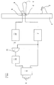
- FIG. 1 a device for contactless control of a shower is shown schematically.
- a shower head 1 is mounted as a standing shower on a building wall 2.
- a first sensor 3 and a second sensor 4 are integrated in the building wall 2. They are used for contactless detection of an object or a person in a detection area 5 or 6 assigned to them.
- the exact construction of sensors 3 and 4 is of no interest in the present context. Any sensor that can be assigned a defined detection range is suitable.
- sensors come into question that work according to the reflection principle, that is, they emit radiation and receive it again after reflection on the object or person. The most common in this context are sensors that work with infrared radiation.
- a larger detection area 5 is assigned to the first sensor 3 and a smaller detection area 6 to the second sensor 4.
- the range of the larger detection area 5 is approximately 50 cm, calculated from the wall 2; the range of the smaller detection area 6, on the other hand, is only about 10 cm, again calculated from the wall 2.
- the ranges are dimensioned such that a user of the shower 1 is normally within the larger detection area 5, but not within the smaller detection area 6.
- the first sensor 3, to which the larger detection area 5 is assigned, is used in the usual way for contactless control of the shower 1 in the sense that the water flow through the shower 1 is released as long as the presence of a person in the detection area 5 of the first Sensor 3 is determined.
- a first detection circuit 7 generates all those signals which are necessary for the operation of the first sensor 3.
- the pulse sequences required for energizing the transmitter diode are provided with the desired frequencies in the first detection circuit 7.
- the detection circuit 7 also contains all those circuit elements which are necessary for evaluating the output signals generated by the sensor 3.
- the size of the first detection area 5 can be set by the choice of the operating parameters of the various circuit components that are located within the first detection circuit 7. If, as an example, a sensor 3 working with infrared light is again selected, the size of the detection range 5 can be varied, for example, by the power of the transmitter diode, by the gain factor of the selective amplifier, or possibly also by the switching threshold of the threshold switch 7. These measures are generally known to the person skilled in the art.
- a signal always appears at the output of the first detection circuit 7 for as long as a person is detected in the first detection area 5 of the first sensor 3.
- This output signal is fed to a driver circuit 8, which then provides the signals required for energizing a solenoid valve 9.
- timing elements can also be contained in a known manner, which delay the switching on or switching off of the solenoid valve 9 by a certain time.
- the second sensor 4, to which the smaller detection area 6 is assigned, is connected to a second detection circuit 10, the internal structure of which essentially corresponds to the first detection circuit 7.
- the operating parameters of the second detection circuit 10 are selected so that the smaller detection area 6 results for the second sensor 4. An always appears at the output of the second detection circuit 10 Signal when an object or a person, preferably the hand of a person, is in the smaller detection area 6 of the second sensor 4.
- the output signal of the second detection circuit 10 is fed to an input of an AND gate 11.
- the output signal of the first detection circuit 7 is at the second input of the AND gate 11.
- the AND gate 11 generates an output signal whenever both the first detection circuit 7 and the second detection circuit 10 generate output signals. This is equivalent to the statement that the AND gate 11 always delivers an output signal when a person or an object is both in the detection area 5 of the first sensor 3 and in the detection area 6 of the second sensor 4.
- the output signal of the AND gate 11 is fed to a logic circuit 12.
- the logic circuit 12 works as follows: Every time the output signal of the AND gate 11 occurs for the first time, the logic circuit 12 determines the switching state of the solenoid valve 9. If the solenoid valve 9 is open, the logic circuit 12 generates an output signal which closes the solenoid valve 9 via the driver circuit 8. Conversely, if the logic circuit 12 determines when the first output signal of the AND gate 11 occurs that the solenoid valve 9 is closed, then it generates an output signal which opens the solenoid valve 9 via the driver circuit 8. In this sense, the logic circuit 12 has the function of a "changeover switch".
- the AND gate 11 on the other hand, does not generate an output signal since it only receives a signal at its input connected to the first detection circuit 7; the second input of the AND gate 11, which is connected to the second detection circuit 10, on the other hand is without a signal since there is no object or person in the smaller detection area 6 of the second sensor 4.
- the logic circuit 12 determines that the solenoid valve 9 is open and, after its function as a changeover switch, generates an output signal which causes the solenoid valve 9 to close via the driver circuit 8.
- the user can now take his hand out of the detection area 6 of the second sensor 4, without anything changing the switching state of the solenoid valve 9. He can soap himself in peace without causing water to flow through the shower head 1, although it is in the detection range 5 of the first sensor 3. If the user then wants to resume the water flow through the shower 1, for example in order to rinse off the soap, he again leads his hand into the detection area 6 of the second sensor 4. An output signal again appears at the output of the second detection circuit 10, which corresponds to that in FIG lower input of the AND gate 11 is supplied. The output of the first detection circuit 7 was at the upper input of the AND gate 11 all the time, since the user has never left the detection range 5 of the first sensor 3.
- the now generated output signal of the AND gate 11 is in turn processed by the logic circuit 12 in the sense of a two-way switch. That is, the logic circuit 12 determines that the solenoid valve 9 is closed and generates an output signal which opens the solenoid valve 9 again via the driver circuit 8. The water begins to flow out of the shower head 1 again until either the user again leads his hand into the smaller detection area 6 of the second sensor 4 or until he himself has left the detection area 5 of the first sensor 3.
- FIG. 2 shows a second exemplary embodiment of a device for contactless control of a shower, the basic function of which corresponds to the exemplary embodiment shown in FIG. 1. Corresponding parts are therefore identified by the same reference number, plus 100.
- FIG. 2 differs from that in Figure 1 essentially in that the various functions that are required to generate the sensor signals or to evaluate the sensor signals in a suitably programmed microprocessor are summarized.
- a simplification compared to the exemplary embodiment in FIG. 1 is also present insofar as only a single sensor is provided which at the same time takes over the functions of the two sensors 3, 4 of the exemplary embodiment from FIG. 1 and is operated alternately for this purpose in different ways.
- This exemplary embodiment is based on the knowledge that the function given in FIG.
- the AND gate 11 does not have to take place simultaneously in the strict sense, but rather that it is sufficient if the presence of a person or an object in the larger and in the smaller surveillance area at intervals that are small compared to the periods during which a person is normally below the shower head.
- the shower head 101, the building wall 102, the driver circuit 108 and the solenoid valve 109 that is energized by the driver circuit 108 can initially be recognized identically from FIG.
- a single sensor 103 is provided, to which a single detection circuit 107 is assigned.
- the basic construction of the detection circuit 107 can correspond to the detection circuits 7 and 10 of the exemplary embodiment from FIG. 1. However, its internal operating parameters are periodically changed so that a large detection area 105 and a small detection area 106 of the (single) sensor 103 alternate at short time intervals.
- the change between the two operating states of the sensor 103 must take place so quickly that, for practical purposes, the measurements which take place in successive operating states of the sensor 103 can be understood as "simultaneously". As a rule, at least some changes in the operating state of the sensor 103 should take place every second.
- the frequency at which the operating state of the sensor 103 is changed is only limited by the speed at which the entire electronic circuit arrangement can process signals.
- the detection circuit 107 is activated in the manner described, as is the evaluation of the signals supplied by the detection circuit 107 by a correspondingly controlled microprocessor 113.
- the output signals of the detection circuit 107 are evaluated, in short, in the following manner: If the microprocessor 113 determines that only in those times in which the sensor 103 is operated with the larger detection area 105, an output signal is emitted by the detection circuit 107, it has the driver circuit 108 open the solenoid valve 109 during this circuit state. This corresponds to the normal operation of a non-contact shower.
- the microprocessor 113 determines that in successive operating states of the sensor 103 with a larger detection area 105 and a smaller detection area 106, an output signal is emitted by the detection circuit 107, then it exercises the function of a "changeover switch" already described above for the logic circuit 12. That is, it causes the driver circuit 108 to change the respective switching state of the solenoid valve 109 to the opposite switching state. In other words: if the solenoid valve is initially open, it is closed and vice versa. Again, the microprocessor 113 performs this function of the "changeover switch" only when output signals of the detection circuit 107 occur for the first time in succession with detection areas 105 and 106 of different sizes.
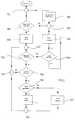
- FIG. 3 shows a logic flow diagram which illustrates the type of programming of the microprocessor 113 from FIG. 2.
- Object field detection describes the function of the device in which the presence of a person and / or an object in the larger detection area 105 of the sensor 103 is queried.
- Touch field detection means the query of a person and / or an object in the smaller detection area 106 of the sensor 103.
- the program steps shown in FIG. 3 are carried out as follows: After the first start of the program, which can be connected with initialization procedures that are not of interest here, point 301 is reached, which is the starting point for the following considerations. An object field detection takes place in the first program step 302. If no person is found in the larger detection area 105 of sensor 103, the program returns to point 301 via point 303 and block 304. In block 304, various tests are carried out which check the readiness and functionality of the entire device and which are of no interest in the present context.
- the program now goes to block 305, which corresponds to the opening of the solenoid valve 109.
- the object field detection is continued, as represented by the branch point 310 in FIG. 3. If the presence of a user in the larger detection area 105 persists (answer "yes" after the branch point 310), a touch field detection is carried out. If this reveals that there is no object or no person in the smaller detection area 106 of the sensor 103, the program goes back via point 312 to point 313, which lies before branch 310 "object field detection”.
- the program now runs through a loop from program point 313 via branch 310, branch 311 and program point 312 back to program point 313. As long as this loop is run through, the solenoid valve 109 remains open.
- the manner of closing the solenoid valve 109 just described corresponds to the normal stopping of the water flow from the shower head 101 when the user leaves the room below the shower head 101.
- the flow of water from the shower head 101 after positive object field detection can, however, be interrupted in a second way: namely, if the touch field detection at branching point 311 turns out positive, that is, after previous positive object field detection at branching point 310, an additional positive touch field Detection found at branch point 311, the program now goes to branch point 316.
- branch point 316 the position of the solenoid valve 109 is checked again. If the branching point 316 is reached for the first time, the solenoid valve 109 is normally open, that is to say "not closed” in the diction of FIG. 3.
- the program now goes to block 317, which corresponds to the closing of solenoid valve 109.
- the program then returns to node 313 via nodes 318 and 312.
- the branch point 311 is reached again.
- the touchpad detection at the branch point 311 is now negative, regardless of whether the user is still in the small detection area 106 of the sensor 103 or has already moved away from this detection area.
- the microprocessor 113 now works with the valve 109 closed, in the loop which leads back from the switching point 313 via the branching points 310, 311 and the switching point 312 to the switching point 313.
- This state in which the solenoid valve 109 is closed, can be ended in two ways: Either the object field detection taking place at the branch point 310 determines that the user has left the large detection area 105 (without a water flow having previously occurred again). The program then proceeds from branch point 310 to branch point 314. This determines that the valve is not open. As already explained above, this has the consequence that the program proceeds to program point 303 and enters the waiting loop 301-302-303-304-301 via it.
- the second possibility to leave the loop 313-310-311-312-313 is, if the positive object field detection continues, that for the first time the touch field detection in the branch point 311 turns out positive, that is, the user again puts his hand in the smaller one Detected area 106 of the sensor 103 has introduced.
- the program proceeds from branch point 311 to branch point 316.
- the solenoid valve 109 is closed, which leads to the opening of the solenoid valve in block 110.
- the program goes over the program items 318 and 312 back into loop 313-310-311-312-313.
- the switching state of the solenoid valve 109 does not change during the cyclical passage through this loop.
- the water now runs again via the shower head 101 until either the user emerges from the larger detection area 105 of the sensor 103 (object field detection at the branching point 310 negative) or until the user again inserts his hand into the smaller detection area 106 of the sensor 103 (touch field -Detection at branch point 311 positive).
- the object field detections carried out in program steps 302 and 310 in the inner program sequence of microprocessor 113 are temporally correlated with the operation of sensor 103 in the larger detection area 106. This can be done by a corresponding control of the detection circuit 107 by the microprocessor 113.
- the microprocessor 113 can then always use the value stored in the buffer during the object field detection in the program steps 302 and 310.
- Program steps 310 and 311 also perform a kind of AND function in the exemplary embodiment according to FIG. 2, because the switching state of the solenoid valve 109 only changes when both the object field detection and the touch field detection are positive.
- the fact that object field detection and touch field detection are not exactly simultaneous is irrelevant as long as the sequence of object field detection and touch field detection takes place relatively quickly. This has already been referred to above.
- two completely independent sensors were used, which could for example contain two transmit diodes and two receive diodes.
- a single sensor was used which, for example, has a single transmitting and a single receiving diode.
- mixed forms are also possible in principle, in which, for example, two transmitters and one receiver or, conversely, one transmitter and two receivers are used.
Landscapes
- Health & Medical Sciences (AREA)
- Life Sciences & Earth Sciences (AREA)
- Engineering & Computer Science (AREA)
- Hydrology & Water Resources (AREA)
- Public Health (AREA)
- Water Supply & Treatment (AREA)
- Domestic Plumbing Installations (AREA)
- Geophysics And Detection Of Objects (AREA)
- Massaging Devices (AREA)
- Selective Calling Equipment (AREA)
Applications Claiming Priority (2)
| Application Number | Priority Date | Filing Date | Title |
|---|---|---|---|
| DE4106539 | 1991-03-01 | ||
| DE4106539A DE4106539C2 (de) | 1991-03-01 | 1991-03-01 | Einrichtung zur berührungslosen Steuerung einer Dusche |
Publications (3)
| Publication Number | Publication Date |
|---|---|
| EP0501263A2 true EP0501263A2 (fr) | 1992-09-02 |
| EP0501263A3 EP0501263A3 (en) | 1993-03-17 |
| EP0501263B1 EP0501263B1 (fr) | 1995-01-11 |
Family
ID=6426234
Family Applications (1)
| Application Number | Title | Priority Date | Filing Date |
|---|---|---|---|
| EP92102579A Expired - Lifetime EP0501263B1 (fr) | 1991-03-01 | 1992-02-16 | Dispositif pour la télécommande d'une douche |
Country Status (4)
| Country | Link |
|---|---|
| EP (1) | EP0501263B1 (fr) |
| AT (1) | ATE117035T1 (fr) |
| DE (1) | DE4106539C2 (fr) |
| ES (1) | ES2069326T3 (fr) |
Cited By (9)
| Publication number | Priority date | Publication date | Assignee | Title |
|---|---|---|---|---|
| DE9211188U1 (de) * | 1992-08-20 | 1993-09-16 | Lepel, Freifrau von, Barbara, 74199 Untergruppenbach | Auslaufarmatur mit Näherungssensor |
| WO1996028618A1 (fr) * | 1995-03-10 | 1996-09-19 | Harald Schrott | Robinetterie a eau |
| FR2761446A1 (fr) * | 1997-03-28 | 1998-10-02 | Celec Conception Electronique | Robinet d'eau automatique a commande sans contact |
| EP0864700A3 (fr) * | 1997-03-14 | 1999-05-19 | Oras Oy | Système de douche |
| EP1159909A1 (fr) * | 2000-05-30 | 2001-12-05 | Leda S.A. | Cabine de douche |
| EP1209293A3 (fr) * | 2000-11-28 | 2003-03-12 | Kludi GmbH & Co. KG | Capteur pour commander une robinetterie d'eau |
| DE102004041786A1 (de) * | 2004-08-30 | 2006-03-02 | Hansa Metallwerke Ag | Sanitärarmatur |
| WO2012152495A1 (fr) * | 2011-05-12 | 2012-11-15 | Enocean Gmbh | Appareil électrique pourvu de système de détection à capteurs |
| AT519532A1 (de) * | 2016-12-19 | 2018-07-15 | Wimtec Sanitaerprodukte Gmbh | Verfahren zum energieeffizienten Betrieb einer Schaltungsanordnung sowie Annäherungssensoren und Schaltungsanordnungen zum Durchführen dieses Verfahrens |
Families Citing this family (11)
| Publication number | Priority date | Publication date | Assignee | Title |
|---|---|---|---|---|
| DE4415234A1 (de) * | 1994-04-30 | 1995-11-02 | Lepel Barbara Freifrau Von | Verfahren zum Betrieb einer Auslaufarmatur und eine nach dem Verfahren arbeitende Auslaufarmatur |
| DE19501014A1 (de) * | 1995-01-14 | 1996-07-18 | Grohe Armaturen Friedrich | Automatische Duschensteuerung |
| DE19510218C2 (de) * | 1995-03-21 | 2000-03-09 | Grohe Kg Hans | Elektrisch betätigbares Sanitärventil |
| DE19625252A1 (de) * | 1996-06-25 | 1998-01-02 | Brand Gerhart Rosemarie | Wasserauslauf mit manueller und automatischer Bedienung |
| ES2224783B1 (es) * | 1997-06-24 | 2005-12-16 | Compañia Roca Radiadores, S.A. | Sistema de control para el accionamiento, sin contacto, del suministro de agua en aparatos sanitarios. |
| DE19743477A1 (de) * | 1997-10-01 | 1999-04-29 | Fraunhofer Ges Forschung | Duschanordnung mit Strahlarteinstellung |
| DE19962742B4 (de) * | 1999-12-23 | 2009-05-07 | Artweger Gmbh & Co. | Sanitäreinrichtung |
| DE10219944C1 (de) * | 2002-05-03 | 2003-12-11 | Hansa Metallwerke Ag | Einrichtung zur berührungslosen Steuerung einer Dusche |
| DE102004027948C5 (de) * | 2004-06-08 | 2010-01-28 | Hansa Metallwerke Ag | Sanitärarmatur mit einer Schaltungsanordnung |
| MXPA06009223A (es) * | 2006-08-14 | 2008-02-13 | Juan Miguel Cordero Gome Campo | Regadera ahorradora de agua. |
| DE102007011183B4 (de) * | 2007-03-06 | 2014-04-17 | Aquis Sanitär AG | Elektrisch betätigbare Sanitäraramtur |
Family Cites Families (8)
| Publication number | Priority date | Publication date | Assignee | Title |
|---|---|---|---|---|
| CH496281A (de) * | 1969-03-11 | 1970-09-15 | Groen Johannes | Vorrichtung zur Abgabe einer Flüssigkeit mit wenigstens einem von einem Annäherungsdetektor gesteuerten elektromagnetischen Ventil |
| AT326573B (de) * | 1974-04-10 | 1975-12-29 | Kuhnel Robert J W Dipl Ing | Optoelektronische wassersteuerung |
| AT364322B (de) * | 1980-01-17 | 1981-10-12 | Robert Kuehnel Ges M B H Dipl | Elektronische steuerungsanordnung zur steuerung des wasserflusses bei waschbecken, spuelanlagen u. dgl. |
| DE3008025A1 (de) * | 1980-03-01 | 1981-09-10 | Georg Rost & Söhne, 4952 Porta Westfalica | Radar-sonde zur steuerung von sanitaerarmaturen |
| IT1221043B (it) * | 1981-05-25 | 1990-06-21 | Dmp Electronics Srl | Rubinetto ad erogazione automatica |
| FR2585147B1 (fr) * | 1985-07-18 | 1989-08-25 | Ferbos Pierre | Robinetterie " econome " traditionnelle ou automatique a volonte |
| DE3629580C1 (de) * | 1986-08-30 | 1987-07-09 | Hansa Metallwerke Ag | Schaltungsanordnung zur beruehrungslosen Steuerung einer Sanitaerarmatur |
| DE3642698C2 (de) * | 1986-12-13 | 1996-09-26 | Grohe Armaturen Friedrich | Automatische Duschensteuerung |
-
1991
- 1991-03-01 DE DE4106539A patent/DE4106539C2/de not_active Expired - Fee Related
-
1992
- 1992-02-16 ES ES92102579T patent/ES2069326T3/es not_active Expired - Lifetime
- 1992-02-16 EP EP92102579A patent/EP0501263B1/fr not_active Expired - Lifetime
- 1992-02-16 AT AT92102579T patent/ATE117035T1/de not_active IP Right Cessation
Cited By (13)
| Publication number | Priority date | Publication date | Assignee | Title |
|---|---|---|---|---|
| DE9211188U1 (de) * | 1992-08-20 | 1993-09-16 | Lepel, Freifrau von, Barbara, 74199 Untergruppenbach | Auslaufarmatur mit Näherungssensor |
| WO1996028618A1 (fr) * | 1995-03-10 | 1996-09-19 | Harald Schrott | Robinetterie a eau |
| US5961095A (en) * | 1995-03-10 | 1999-10-05 | Schrott; Harald | Electronically controlled water faucet |
| EP0864700A3 (fr) * | 1997-03-14 | 1999-05-19 | Oras Oy | Système de douche |
| FR2761446A1 (fr) * | 1997-03-28 | 1998-10-02 | Celec Conception Electronique | Robinet d'eau automatique a commande sans contact |
| FR2809609A1 (fr) * | 2000-05-30 | 2001-12-07 | Leda | Cabine de douche |
| EP1159909A1 (fr) * | 2000-05-30 | 2001-12-05 | Leda S.A. | Cabine de douche |
| EP1209293A3 (fr) * | 2000-11-28 | 2003-03-12 | Kludi GmbH & Co. KG | Capteur pour commander une robinetterie d'eau |
| DE102004041786A1 (de) * | 2004-08-30 | 2006-03-02 | Hansa Metallwerke Ag | Sanitärarmatur |
| DE102004041786B4 (de) * | 2004-08-30 | 2008-12-18 | Hansa Metallwerke Ag | Sanitärarmatur |
| WO2012152495A1 (fr) * | 2011-05-12 | 2012-11-15 | Enocean Gmbh | Appareil électrique pourvu de système de détection à capteurs |
| AT519532A1 (de) * | 2016-12-19 | 2018-07-15 | Wimtec Sanitaerprodukte Gmbh | Verfahren zum energieeffizienten Betrieb einer Schaltungsanordnung sowie Annäherungssensoren und Schaltungsanordnungen zum Durchführen dieses Verfahrens |
| AT519532B1 (de) * | 2016-12-19 | 2018-10-15 | Wimtec Sanitaerprodukte Gmbh | Verfahren zum energieeffizienten Betrieb einer Schaltungsanordnung sowie Annäherungssensoren und Schaltungsanordnungen zum Durchführen dieses Verfahrens |
Also Published As
| Publication number | Publication date |
|---|---|
| EP0501263A3 (en) | 1993-03-17 |
| DE4106539A1 (de) | 1992-09-03 |
| ATE117035T1 (de) | 1995-01-15 |
| ES2069326T3 (es) | 1995-05-01 |
| EP0501263B1 (fr) | 1995-01-11 |
| DE4106539C2 (de) | 1994-12-15 |
Similar Documents
| Publication | Publication Date | Title |
|---|---|---|
| EP0501263B1 (fr) | Dispositif pour la télécommande d'une douche | |
| DE69709967T2 (de) | Vorrichtung zum Steuern einer Gruppe von Badezimmergeräten | |
| DE69320549T2 (de) | Toilettengarnitur | |
| DE68917419T2 (de) | Verfahren für Eindringalarm und System dafür. | |
| DE69600972T2 (de) | Vorrichtung zur Feststellung von Annäherungen | |
| DE10219126B4 (de) | Photoelektrischer Sensor | |
| DE3618693A1 (de) | Verfahren und vorrichtung zur feststellung der anwesenheit eines menschlichen koerpers | |
| EP0463440B1 (fr) | Méthode d'utilisation de circuit destiné à commander sans contact une armature sanitaire et circuit pour la réalisation de cette méthode | |
| EP0632290A1 (fr) | Appareil et procédé de commande sans contact du débit d'eau dans une installation sanitaire | |
| CH629349A5 (de) | Schaltungsanordnung zur frequenz-selbststeuerung eines ultraschall-sendewandlers. | |
| DE102016120016A1 (de) | Überwachungsvorrichtung für eine sanitäre Anlage | |
| EP0332045B1 (fr) | Appareil de commande sans contact d'installations sanitaires | |
| DE1284137B (de) | Anordnung zum Anzeigen eines Objekts auf oder vor einer Flaeche | |
| DE1524151C2 (de) | Schaltungsanordnung zur Verbindung des Speicherwerkes einer Zentralen Datenverarbeitungsanlage mit asynchronarbeitenden angeschlossenen Dateneinheiten | |
| DE3210985C3 (de) | Berührungslose elektronische Steuerung für eine sanitäre Armatur, insbesondere ein Urinal | |
| EP0768545B1 (fr) | Procédé pour faire fonctionner un transducteur optique | |
| AT15321U1 (de) | Anwesenheitsdetektion mittels Schall | |
| DE2721254C3 (de) | Schaltungsanordnung für einen Bewegungsdetektor | |
| EP0531646B1 (fr) | Circuit de commande sans contact d'une armature sanitaire et procédé de commande de celui-ci | |
| CH531278A (de) | Annäherungsschalter | |
| DE102007009038A1 (de) | Sanitärarmatur mit wählbarer Betriebsart | |
| DE2755665C2 (de) | Steuervorrichtung für den Wasserzufluß in Waschbecken od.dgl. mit einem Ultraschall-Rückstrahl-Ortungsgerät als Annäherungsschalter | |
| DE3629580C1 (de) | Schaltungsanordnung zur beruehrungslosen Steuerung einer Sanitaerarmatur | |
| DE10200905B4 (de) | Photoelektrischer Schalter | |
| DE102004027948B4 (de) | Sanitärarmatur mit einer Schaltungsanordnung |
Legal Events
| Date | Code | Title | Description |
|---|---|---|---|
| PUAI | Public reference made under article 153(3) epc to a published international application that has entered the european phase |
Free format text: ORIGINAL CODE: 0009012 |
|
| AK | Designated contracting states |
Kind code of ref document: A2 Designated state(s): AT CH ES FR GB IT LI |
|
| PUAL | Search report despatched |
Free format text: ORIGINAL CODE: 0009013 |
|
| AK | Designated contracting states |
Kind code of ref document: A3 Designated state(s): AT CH ES FR GB IT LI |
|
| 17P | Request for examination filed |
Effective date: 19930506 |
|
| 17Q | First examination report despatched |
Effective date: 19940526 |
|
| GRAA | (expected) grant |
Free format text: ORIGINAL CODE: 0009210 |
|
| AK | Designated contracting states |
Kind code of ref document: B1 Designated state(s): AT CH ES FR GB IT LI |
|
| REF | Corresponds to: |
Ref document number: 117035 Country of ref document: AT Date of ref document: 19950115 Kind code of ref document: T |
|
| ITF | It: translation for a ep patent filed | ||
| ET | Fr: translation filed | ||
| REG | Reference to a national code |
Ref country code: ES Ref legal event code: FG2A Ref document number: 2069326 Country of ref document: ES Kind code of ref document: T3 |
|
| GBT | Gb: translation of ep patent filed (gb section 77(6)(a)/1977) |
Effective date: 19950413 |
|
| PLBE | No opposition filed within time limit |
Free format text: ORIGINAL CODE: 0009261 |
|
| STAA | Information on the status of an ep patent application or granted ep patent |
Free format text: STATUS: NO OPPOSITION FILED WITHIN TIME LIMIT |
|
| 26N | No opposition filed | ||
| PGFP | Annual fee paid to national office [announced via postgrant information from national office to epo] |
Ref country code: GB Payment date: 20010213 Year of fee payment: 10 |
|
| REG | Reference to a national code |
Ref country code: GB Ref legal event code: IF02 |
|
| PG25 | Lapsed in a contracting state [announced via postgrant information from national office to epo] |
Ref country code: GB Free format text: LAPSE BECAUSE OF NON-PAYMENT OF DUE FEES Effective date: 20020216 |
|
| GBPC | Gb: european patent ceased through non-payment of renewal fee |
Effective date: 20020216 |
|
| PG25 | Lapsed in a contracting state [announced via postgrant information from national office to epo] |
Ref country code: IT Free format text: LAPSE BECAUSE OF NON-PAYMENT OF DUE FEES Effective date: 20050216 |
|
| PGFP | Annual fee paid to national office [announced via postgrant information from national office to epo] |
Ref country code: ES Payment date: 20080215 Year of fee payment: 17 Ref country code: CH Payment date: 20080229 Year of fee payment: 17 |
|
| PGFP | Annual fee paid to national office [announced via postgrant information from national office to epo] |
Ref country code: AT Payment date: 20080229 Year of fee payment: 17 |
|
| PGFP | Annual fee paid to national office [announced via postgrant information from national office to epo] |
Ref country code: FR Payment date: 20080229 Year of fee payment: 17 |
|
| REG | Reference to a national code |
Ref country code: CH Ref legal event code: PL |
|
| PG25 | Lapsed in a contracting state [announced via postgrant information from national office to epo] |
Ref country code: LI Free format text: LAPSE BECAUSE OF NON-PAYMENT OF DUE FEES Effective date: 20090228 Ref country code: CH Free format text: LAPSE BECAUSE OF NON-PAYMENT OF DUE FEES Effective date: 20090228 Ref country code: AT Free format text: LAPSE BECAUSE OF NON-PAYMENT OF DUE FEES Effective date: 20090216 |
|
| REG | Reference to a national code |
Ref country code: FR Ref legal event code: ST Effective date: 20091030 |
|
| REG | Reference to a national code |
Ref country code: ES Ref legal event code: FD2A Effective date: 20090217 |
|
| PG25 | Lapsed in a contracting state [announced via postgrant information from national office to epo] |
Ref country code: FR Free format text: LAPSE BECAUSE OF NON-PAYMENT OF DUE FEES Effective date: 20090302 |
|
| PG25 | Lapsed in a contracting state [announced via postgrant information from national office to epo] |
Ref country code: ES Free format text: LAPSE BECAUSE OF NON-PAYMENT OF DUE FEES Effective date: 20090217 |