EP0501328B1 - Régulateur de débit - Google Patents
Régulateur de débit Download PDFInfo
- Publication number
- EP0501328B1 EP0501328B1 EP92102922A EP92102922A EP0501328B1 EP 0501328 B1 EP0501328 B1 EP 0501328B1 EP 92102922 A EP92102922 A EP 92102922A EP 92102922 A EP92102922 A EP 92102922A EP 0501328 B1 EP0501328 B1 EP 0501328B1
- Authority
- EP
- European Patent Office
- Prior art keywords
- valve element
- valve
- elastic member
- stem
- upward
- Prior art date
- Legal status (The legal status is an assumption and is not a legal conclusion. Google has not performed a legal analysis and makes no representation as to the accuracy of the status listed.)
- Expired - Lifetime
Links
- 239000012530 fluid Substances 0.000 title claims description 30
- 125000006850 spacer group Chemical group 0.000 description 5
- 238000010276 construction Methods 0.000 description 2
- 230000000694 effects Effects 0.000 description 2
- 239000007787 solid Substances 0.000 description 2
- 230000037431 insertion Effects 0.000 description 1
- 238000003780 insertion Methods 0.000 description 1
- 230000002093 peripheral effect Effects 0.000 description 1
- 238000007789 sealing Methods 0.000 description 1
Images
Classifications
-
- F—MECHANICAL ENGINEERING; LIGHTING; HEATING; WEAPONS; BLASTING
- F16—ENGINEERING ELEMENTS AND UNITS; GENERAL MEASURES FOR PRODUCING AND MAINTAINING EFFECTIVE FUNCTIONING OF MACHINES OR INSTALLATIONS; THERMAL INSULATION IN GENERAL
- F16K—VALVES; TAPS; COCKS; ACTUATING-FLOATS; DEVICES FOR VENTING OR AERATING
- F16K1/00—Lift valves or globe valves, i.e. cut-off apparatus with closure members having at least a component of their opening and closing motion perpendicular to the closing faces
-
- F—MECHANICAL ENGINEERING; LIGHTING; HEATING; WEAPONS; BLASTING
- F16—ENGINEERING ELEMENTS AND UNITS; GENERAL MEASURES FOR PRODUCING AND MAINTAINING EFFECTIVE FUNCTIONING OF MACHINES OR INSTALLATIONS; THERMAL INSULATION IN GENERAL
- F16K—VALVES; TAPS; COCKS; ACTUATING-FLOATS; DEVICES FOR VENTING OR AERATING
- F16K41/00—Spindle sealings
- F16K41/10—Spindle sealings with diaphragm, e.g. shaped as bellows or tube
Definitions
- the present invention relates to a fluid controller comprising a valve element which is movable upward or downward by rotating a valve stem to open or close a fluid channel.
- valve element is movable upward or downward by rotating the valve stem to move the stem upward or downward.
- the valve element is brought into contact with and seated in a valve seat to close a fluid channel by being moved downward.
- the valve element is brought out of contact with the valve seat to open the fluid channel by being moved upward.
- the valve stem and the valve element are provided as separate members, and the lower end of the stem is rotatably attached to the upper end of the element so that the valve element will not rotate with the stem when coming into contact with the valve seat.
- Fluid controllers include those wherein the valve element bites into the valve seat with a wedge effect when seated in the seat to completely close the fluid channel.
- valve element leaves the seat, the element is pushed toward the valve stem by the pressure of fluid and thereby moved upward by an amount corresponding to the backlash to strike against the stem.
- the same phenomenon as above occurs also in the case of valves having bellows or diaphragm incorporated therein. Accordingly, the striking contact of the valve element with the valve stem gives off a noise, causing the user discomfort. Further especially when the fluid controller is used for controlling the rate of flow, extreme difficulty is encountered in finely adjusting the flow rate between the fully closed position and a slightly opened position.
- FIG. 11 In US-A-3 278 156 another embodiment of a fluid controller is disclosed (figures 11 and 12), wherein the valve element is urged against a cup by an elastic member, i. e. a spiral spring.
- the cap is screwed on a housing surrounding the valve element and the spiral spring.
- the main object of the present invention is to provide a fluid controller which produces no striking noise when the fluid channel is slightly opened from the fully closed position and which is adapted for the fine adjustment of flow rate.
- valve element and the valve stem are connected almost immovable axially thereof relativ to each other and that the elastic member is urging the valve element only in a first range of movement wherein the valve element is in a seated position or in the vicinity of the seated position, and that the elastic member is not urging the valve element, when the valve element is in a second range of movement, which is located above the first range.
- the fluid controller of the present invention gives off no striking noise when the fluid channel is slightly opened from the fully closed position and is usable for the fine adjustment of flow rate as will be described below.
- valve element In the vicinity of the seated position, the valve element is urged upward and pressed against the valve seat by the elastic member, so that even if the valve element is caused to bite into the seat when seated in the seat to fully close the channel, the valve element immediately moves upward out of contact with the seat while being pressed against the stem by the elastic member, when the valve element is slightly rotated in the opening direction and thereby slightly moved upward. Unlike the prior art, therefore, this eliminates the likelihood that the valve element will move at a time by an amount corresponding to the backlash to strike against the valve stem. Thus, the valve element produces no striking noise. Further the flow through the channel is finely adjustable because in the vicinity of the seated position, the valve element is movable following the movement, if slight, of the valve stem.
- the elastic member is disposed between the upper surface of a guide portion for guiding the valve element and a flangelike portion fixedly provided on a portion of the valve element above the guide portion both the guide portion and the flange-like portion are contacting the elastic member only when the valve element is in the first range of movement.
- the elastic member is disposed on the upper surface of the guide portion, the flangelike portion is contacting the elastic member, when the valve element is in the first range of movement, the flange-like portion being upwardly away from the elastic member when the valve element is in the second range.
- the elastic member comprises a disc spring.
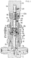
- FIG. 1 shows the overall construction of a fluid controller adapted for flow rate adjustment
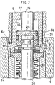
- FIG. 2 shows the main portion of the same in greater detail.
- the fluid controller includes a valve case 1 which has an upwardly projecting cylindrical portion 1a, a valve stem bore 2 having a large diameter and extending from the upper end of the cylindrical portion 1a to an intermediate portion of the height of the valve case 1, and a guide bore 3 having a small diameter and extending from the bottom of the bore 2 to a lower portion of the valve case 1.
- a fluid channel 4 is formed by a passage extending from one side face of the case 1 to an intermediate portion of the guide bore 3, the bottom portion of the stem bore 2, and a passage extending from this portion to the other side face of the valve case 1.
- a downwardly tapered annular valve seat 5 is provided at the upper end of the guide bore 3.
- a valve closure 6 in the form of a stepped cylinder has a lower portion which is screwed around the cylindrical portion 1a of the valve case 1. More than the lower-half part of the valve closure 6 is a large-diameter portion 6a which is large in inside and outside diameters, and the remaining upper part thereof is a small-diameter portion 6b which is small in inside and outside diameters. An annular shoulder 6c is provided between these portions 6a, 6b. The lower end part of the large-diameter portion 6a of the closure 6 is screwed on the cylindrical portion 1a of the case 1. The small-diameter portion 6b of the closure 6 is insertable through a mount hole in a panel (not shown). The panel is to be held between the shoulder 6c and a nut 7 screwed on the small-diameter portion 6b.
- a valve stem support member 8 which is in the form of a stepped bored cylinder, is formed with an outer flange 9 at a lower portion thereof. Fitted inside the large-diameter portion 6a of the valve closure 6 are the portion of the support member 8 not higher than the flange 9, a valve element guide member 10 in the form of a bore short cylinder and serving also as a spring retainer, and a hollow cylindrical spacer 11. These are held between the shoulder 6c of the closure 6 and the upper end of the cylindrical portion 1a of the valve case 1. The lower end of the spacer 6 is smaller in outside diameter than the other portion thereof and is fitted in the upper end of the stem bore 2 of the case 1 which is slightly larger in inside diameter than the other bored portion.
- a gasket 12 seals off the joint between the spacer 11 and the case cylindrical portion 1a.
- the spacer 11 has an upper end portion which is greater than the other portion thereof in inside diameter and which has fitted therein the diametrically greater upper portion of the guide member 10 and the lower end of the stem support member 8.
- the joint between the spacer 11 and the guide member 10 is sealed off by a gasket 13.
- the portion of the support member 8 above its flange 9 fits in the small-diameter portion 6b of the closure 6 and further extends upward beyond the upper end of the portion 6b.
- the support member 8 has an upper end portion having a slightly reduced outside diameter.
- An indicator 14 in the form of a hollow cylinder is fitted around this portion and fixed thereto with a setscrew 15.
- the stem support member 8 has a large-diameter bore 16 formed in its lower portion and a small-diameter bore 17 extending upward therefrom.
- the upper and lower bores extend through the member 8.
- the bored portion indicated at 17 has a female screw 18 at an upper part thereof.
- a valve stem 19 is inserted through these bores 16, 17.
- the valve stem 19 has an externally threaded upper portion 20, which is screwed in the female screw 18 of the support member 8.
- the valve stem 19 is formed at its lower end with a large-diameter portion 19a which has a larger outside diameter than the other portion thereof and which is fitted in the large-diameter bore 16 of the support member 8.
- An O-ring 21 is attached to the outer periphery of the large-diameter portion 19a for sealing off the clearance between the portion 19a and the support member 8.
- the portion of the valve stem 19 above the male screw 20 extends upward beyond the upper ends of the support member 8 and the indicator 14 and has a solid cylindrical knob 22 fitted around the stem and fixed thereto with a setscrew 23.
- the knob 22 has at its lower end a hollow cylindrical portion 22a, which is fitted around the indicator 14.
- the peripheral wall of the support member 8 defining the small-diameter bore 17 has a lock screw 24 attached thereto.
- the valve stem 18 is rotated and thereby moved upward or downward by rotating the knob 22 with the lock screw 24 loosened, and is fixed in a desired position by tightening up the lock screw 24.
- the indicator 14 indicates the amount of upward or downward movement of the valve stem 19.
- the large-diameter portion 19a of the valve stem 19 is formed with an insertion cavity 25 extending upward from its bottom face.
- a valve element 26 has an upper portion inserted in the cavity 25.
- the valve member 26 is generally in the form of a vertically elongated solid cylinder and extends downward through the guide member 10.
- the portion of the valve element 26 inserted in the cavity 25 has an annular groove 27 toward its upper end, and a flange 28 at its upper end.
- the valve stem large-diameter portion 19a is fixedly provided with a pin 29 in parallel to a diametrical direction thereof.
- the pin has an intermediate portion partly fittedin the groove 27 of the upper portion of the valve element 26.
- valve stem 19 and the valve element 26 are almost immovable upward or downward (axially thereof) relative to each other. It is desirable to minimize the backlash between the flange 28 of the valve element 26 and the top wall defining the cavity 25 and positioned thereabove, as well as between the flange and the pin 29 therebelow, whereas some backlash inevitably occurs therebetween.
- the valve element 26 is formed at its lower end with a tapered guide rod 26a of small diameter and a downwardly tapered conical face 26b positioned above the rod.
- the taperd rod 26b fits into the guide bore 3, and the conical face 26b is brought into contact with and seated in the valve seat 5 to close the channel 4.
- the conical face 26b is moved upward out of contact with the valve seat 5 to open the channel 4.
- Bellows 30 are provided between the lower portion of the guide member 10 and an inverted conical portion 26c formed on the valve element 26 slightly above the conical face 26b to seal off the element between these portions. The upper and lower ends of the bellows 30 are secured to these portions in intimate contact therewith.
- a spring retainer 31 in the form of a retaining ring is fixed to the outer periphery of the valve element 26 immediately below the valve stem 19.
- a disc spring 32 serving as an elastic member is provided on the guide member 10. The disc spring 32 is in pressing contact with the spring retainer 31 when the valve element 26 is in the vicinity of its seated position, urging the valve element 26 upward and pressing the upper end face thereof into contact with the top wall of the valve stem 19 defining the cavity 25.
- valve stem 19 and the valve element 26 move upward, bringing the conical face 26b of the element 26 out of contact with the seat 5 to open the channel 4.
- the large-diameter portion 19a of the stem 19 is moved to the top of the large-diameter bore 16 of the support member 8 to position the spring retainer 31 of the valve element 26 upwardly away from the disc spring 32. Accordingly, the valve element 26 will not be urged upward by the disc spring 32 but is upwardly urged by the bellows 30 and pressed against the valve stem 19 with a relatively small force.
- valve stem 19 and the valve element 26 move down.
- the spring retainer 31 on the valve element 26 comes into contact with the disc spring 32, which in turn urges the valve element 26 upward into pressing contact with the valve stem 19 with a greater force than previously.
- the conical face 26b of the valve element 26 is brought into contact with and seated in the valve seat 5, fully closing the channel 4, the valve element 26 is pressed against the valve stem 19 with a further increased force due to the reaction from the seat 5.
- valve element 26 When the knob 22 is slightly rotated from the full-closing state, slightly moving the valve stem 19 upward, the valve element, which is upwardly urged and pressed against the valve stem 19 by the disc spring 32, immediately moves upward out of contact with the seat 5 while being pressed against the stem 19 by the disc spring 32, even if the conical face 26b of the valve element 26 in the fully closing position is in biting engagement with the seat 5. Unlike the conventional device, therefore, the valve element 26 will not move at a time by an amount corresponding to the backlash into striking contact with the valve stem 19, hence no striking noise. Furthermore, the flow through the channel 4 is finely adjustable because in the vicinity of the seated position, the valve element 26 is movable following the movement, if slight, of the valve stem 19.
Landscapes
- Engineering & Computer Science (AREA)
- General Engineering & Computer Science (AREA)
- Mechanical Engineering (AREA)
- Lift Valve (AREA)
- Details Of Valves (AREA)
Claims (4)
- Dispositif de commande de fluide comportant un élément obturateur (26) et une tige de robinet (19) fixée avec faculté de rotation au niveau de son extrémité inférieure à l'extrémité supérieure de l'élément obturateur (26), l'élément obturateur (26) pouvant être déplacé vers le haut ou vers le bas en tournant la tige de robinet (19) afin de déplacer la tige de robinet (19) vers le haut ou vers le bas, l'élément obturateur (26) pouvant être déplacé vers le bas jusqu'à une position assise afin de venir en contact avec un siège de robinet (5) et de fermer un conduit de fluide (4), l'élément obturateur (26) pouvant être déplacé vers le haut hors de contact avec le siège de robinet (5) afin d'ouvrir le conduit de fluide (4), le dispositif de commande comportant un élément élastique (32) destiné à pousser l'élément obturateur (26) vers le haut afin de presser l'élément obturateur (26) contre la tige de robinet (19) avec une force prédéterminée, caractérisé en ce que l'élément obturateur (26) et la tige de robinet (19) sont reliés de façon presque immobile l'un par rapport à l'autre dans leur sens axial, et en ce que l'élément élastique (32) ne pousse l'élément obturateur (26) que dans une première plage de déplacement dans laquelle l'élément obturateur (26) est en position assise ou à proximité de la position assise, et en ce que l'élément élastique (32) ne pousse pas l'élément obturateur (26) quand l'élément obturateur (26) est dans une seconde plage de déplacement, qui est située au-dessus de la première plage.
- Dispositif de commande de fluide selon la revendication 1, dans lequel l'élément élastique (32) est disposé entre une surface supérieure d'une partie de guidage (10) destinée à guider l'élément obturateur (26) et une partie en forme de bride (31) disposée fixe sur une partie de l'élément obturateur (26) au-dessus de la partie de guidage (10), la partie de guidage (10) et la partie en forme de bride (31) ne touchant toutes deux l'élément élastique (31) que lorsque l'élément obturateur (26) est dans la première plage de déplacement.
- Dispositif de commande de fluide selon la revendication 2,dans lequel l'élément élastique (32) est disposé sur la surface supérieure de la partie de guidage (10), la partie en forme de bride (31) touchant l'élément élastique (32) lorsque l'élément obturateur (26) est dans la première plage de déplacement, la partie en forme de bride (31) étant distante vers le haut de l'élément élastique (32) lorsque l'élément obturateur (26) est dans la seconde plage.
- Dispositif de commande de fluide selon la revendication 2, dans lequel l'élément élastique (32) est constitué d'un ressort à disques.
Applications Claiming Priority (2)
| Application Number | Priority Date | Filing Date | Title |
|---|---|---|---|
| JP03030922A JP3106366B2 (ja) | 1991-02-26 | 1991-02-26 | 流体制御器 |
| JP30922/91 | 1991-02-26 |
Publications (2)
| Publication Number | Publication Date |
|---|---|
| EP0501328A1 EP0501328A1 (fr) | 1992-09-02 |
| EP0501328B1 true EP0501328B1 (fr) | 1996-02-07 |
Family
ID=12317184
Family Applications (1)
| Application Number | Title | Priority Date | Filing Date |
|---|---|---|---|
| EP92102922A Expired - Lifetime EP0501328B1 (fr) | 1991-02-26 | 1992-02-21 | Régulateur de débit |
Country Status (6)
| Country | Link |
|---|---|
| US (1) | US5351936A (fr) |
| EP (1) | EP0501328B1 (fr) |
| JP (1) | JP3106366B2 (fr) |
| KR (1) | KR950014801B1 (fr) |
| CA (1) | CA2061777C (fr) |
| DE (1) | DE69208112T2 (fr) |
Families Citing this family (18)
| Publication number | Priority date | Publication date | Assignee | Title |
|---|---|---|---|---|
| JP3472650B2 (ja) * | 1995-07-24 | 2003-12-02 | 株式会社フジキン | 流体制御器 |
| US5725198A (en) * | 1996-02-20 | 1998-03-10 | Ohmeda Inc. | Non-rotating needle valve |
| US5630444A (en) * | 1996-04-24 | 1997-05-20 | Snap-Tite, Inc. | High pressure bellows valve |
| US5687949A (en) * | 1996-04-26 | 1997-11-18 | Controls Corporation Of America | Gas flow regulator valve |
| US5904178A (en) * | 1997-06-20 | 1999-05-18 | Controls Corporation Of America | Gas filter for regulator valve, and improved regulator valve employing the filter |
| KR100427229B1 (ko) * | 1999-09-22 | 2004-04-14 | 주식회사 포스코 | 대형 송풍기의 역류방지밸브 |
| US6543748B1 (en) * | 2001-10-03 | 2003-04-08 | Vat Holding Ag | Linear motion leadthrough |
| JP2005163896A (ja) * | 2003-12-02 | 2005-06-23 | Toyoda Mach Works Ltd | 電磁開閉弁 |
| JP2006153042A (ja) * | 2004-11-25 | 2006-06-15 | Surpass Kogyo Kk | 流量調節弁 |
| JP4237781B2 (ja) * | 2006-06-29 | 2009-03-11 | シーケーディ株式会社 | 流量制御弁 |
| CN102563097A (zh) * | 2012-03-02 | 2012-07-11 | 江苏星河集团有限公司 | 新型仪表隔膜阀 |
| US9454158B2 (en) | 2013-03-15 | 2016-09-27 | Bhushan Somani | Real time diagnostics for flow controller systems and methods |
| DE102014004669B3 (de) * | 2014-03-31 | 2015-09-24 | Festo Ag & Co. Kg | Ventil |
| KR20170064222A (ko) * | 2015-12-01 | 2017-06-09 | 티에스케이 주식회사 | 벨로우즈형 스팀 트랩 |
| DE102016100770A1 (de) * | 2016-01-19 | 2017-07-20 | Gemü Gebr. Müller Apparatebau Gmbh & Co. Kommanditgesellschaft | Ventilsystem |
| US10983538B2 (en) | 2017-02-27 | 2021-04-20 | Flow Devices And Systems Inc. | Systems and methods for flow sensor back pressure adjustment for mass flow controller |
| US10935153B2 (en) * | 2019-01-28 | 2021-03-02 | Mac Valves, Inc. | Proportional flow control valve poppet with flow control needle |
| DE102020120439A1 (de) * | 2020-08-03 | 2022-02-03 | Focke & Co. (Gmbh & Co. Kg) | Ventil für fließfähige Medien |
Family Cites Families (10)
| Publication number | Priority date | Publication date | Assignee | Title |
|---|---|---|---|---|
| BE571561A (fr) * | ||||
| US3391901A (en) * | 1964-09-30 | 1968-07-09 | Varian Associates | High vacuum leak valve |
| US3278156A (en) * | 1965-12-27 | 1966-10-11 | Nuclear Products Company | Bellows valve |
| US3990680A (en) * | 1974-07-22 | 1976-11-09 | Robertshaw Controls Company | Valve construction and method of making the same |
| US4201366A (en) * | 1978-03-13 | 1980-05-06 | Danko Oliver L | Bellows valve |
| NL8202513A (nl) * | 1982-06-22 | 1984-01-16 | Amstelstaal Bv | Bedieningsinrichting voor een hoge-drukafsluiter met een kleine doorlaat. |
| US4526341A (en) * | 1983-06-15 | 1985-07-02 | Kerotest Manufacturing Corp. | Pneumatic shut-off valve |
| JPH0792164B2 (ja) * | 1986-04-18 | 1995-10-09 | 山田 満江 | 流動制御機器 |
| FR2621094B3 (fr) * | 1987-09-30 | 1989-12-29 | Beauvir Jacques | Vanne a commande manuelle |
| US4911412A (en) * | 1989-05-19 | 1990-03-27 | Nupro Company | Valves with improved actuators |
-
1991
- 1991-02-26 JP JP03030922A patent/JP3106366B2/ja not_active Expired - Fee Related
-
1992
- 1992-02-21 DE DE69208112T patent/DE69208112T2/de not_active Expired - Fee Related
- 1992-02-21 EP EP92102922A patent/EP0501328B1/fr not_active Expired - Lifetime
- 1992-02-24 US US07/839,557 patent/US5351936A/en not_active Expired - Lifetime
- 1992-02-25 KR KR1019920002863A patent/KR950014801B1/ko not_active Expired - Fee Related
- 1992-02-25 CA CA002061777A patent/CA2061777C/fr not_active Expired - Fee Related
Also Published As
| Publication number | Publication date |
|---|---|
| US5351936A (en) | 1994-10-04 |
| KR950014801B1 (ko) | 1995-12-14 |
| CA2061777C (fr) | 2003-01-14 |
| JP3106366B2 (ja) | 2000-11-06 |
| JPH0510455A (ja) | 1993-01-19 |
| CA2061777A1 (fr) | 1992-08-27 |
| DE69208112D1 (de) | 1996-03-21 |
| EP0501328A1 (fr) | 1992-09-02 |
| DE69208112T2 (de) | 1996-06-27 |
| KR920016752A (ko) | 1992-09-25 |
Similar Documents
| Publication | Publication Date | Title |
|---|---|---|
| EP0501328B1 (fr) | Régulateur de débit | |
| US5439197A (en) | Flow rate control valve | |
| US6068014A (en) | Pressure-reducing valve | |
| US4195656A (en) | Orifice device with safety shut-off for pressure regulators | |
| US20050279956A1 (en) | Valve with reliable opening indication | |
| GB2103391A (en) | Servo operated fluid flow taps and valves | |
| US6273117B1 (en) | Pressure regulator | |
| JPWO2008096646A1 (ja) | 流体制御器 | |
| US4941504A (en) | Manual fluid-control valve with limited closing pressure | |
| EP1031900B1 (fr) | Régulateur | |
| KR20180043728A (ko) | 감압밸브 | |
| EP1715230B1 (fr) | Contrôleur de fluide | |
| CA1278492C (fr) | Soupape de surete | |
| US4103704A (en) | Safety relief valve | |
| US6997209B2 (en) | Locking device of an air-operated normally-closed valve for a gas cylinder | |
| US5573031A (en) | Air bleed valve | |
| US4509721A (en) | Operating mechanism for a high-pressure valve having a valve passage of relatively small width | |
| JP3020451B2 (ja) | 手動弁 | |
| EP0769114B1 (fr) | Vanne d'isolement | |
| EP0043711A1 (fr) | Vanne | |
| JPH0579570A (ja) | 制御器 | |
| AU646561B2 (en) | Jumper valve | |
| US3790124A (en) | Toggle linkage valve actuator | |
| GB2103766A (en) | Push-button tap | |
| KR0133515Y1 (ko) | 유량조절용 콘트롤밸브 |
Legal Events
| Date | Code | Title | Description |
|---|---|---|---|
| PUAI | Public reference made under article 153(3) epc to a published international application that has entered the european phase |
Free format text: ORIGINAL CODE: 0009012 |
|
| AK | Designated contracting states |
Kind code of ref document: A1 Designated state(s): CH DE FR GB IT LI NL |
|
| 17P | Request for examination filed |
Effective date: 19930121 |
|
| 17Q | First examination report despatched |
Effective date: 19940623 |
|
| GRAA | (expected) grant |
Free format text: ORIGINAL CODE: 0009210 |
|
| AK | Designated contracting states |
Kind code of ref document: B1 Designated state(s): CH DE FR GB IT LI NL |
|
| REF | Corresponds to: |
Ref document number: 69208112 Country of ref document: DE Date of ref document: 19960321 |
|
| ET | Fr: translation filed | ||
| ITF | It: translation for a ep patent filed | ||
| PLBE | No opposition filed within time limit |
Free format text: ORIGINAL CODE: 0009261 |
|
| STAA | Information on the status of an ep patent application or granted ep patent |
Free format text: STATUS: NO OPPOSITION FILED WITHIN TIME LIMIT |
|
| 26N | No opposition filed | ||
| REG | Reference to a national code |
Ref country code: GB Ref legal event code: IF02 |
|
| PGFP | Annual fee paid to national office [announced via postgrant information from national office to epo] |
Ref country code: FR Payment date: 20050216 Year of fee payment: 14 |
|
| PGFP | Annual fee paid to national office [announced via postgrant information from national office to epo] |
Ref country code: DE Payment date: 20060109 Year of fee payment: 15 |
|
| PGFP | Annual fee paid to national office [announced via postgrant information from national office to epo] |
Ref country code: NL Payment date: 20060215 Year of fee payment: 15 |
|
| PGFP | Annual fee paid to national office [announced via postgrant information from national office to epo] |
Ref country code: GB Payment date: 20060221 Year of fee payment: 15 Ref country code: CH Payment date: 20060221 Year of fee payment: 15 |
|
| PGFP | Annual fee paid to national office [announced via postgrant information from national office to epo] |
Ref country code: IT Payment date: 20060228 Year of fee payment: 15 |
|
| PG25 | Lapsed in a contracting state [announced via postgrant information from national office to epo] |
Ref country code: CH Free format text: LAPSE BECAUSE OF NON-PAYMENT OF DUE FEES Effective date: 20070228 Ref country code: LI Free format text: LAPSE BECAUSE OF NON-PAYMENT OF DUE FEES Effective date: 20070228 |
|
| REG | Reference to a national code |
Ref country code: CH Ref legal event code: PL |
|
| GBPC | Gb: european patent ceased through non-payment of renewal fee |
Effective date: 20070221 |
|
| NLV4 | Nl: lapsed or anulled due to non-payment of the annual fee |
Effective date: 20070901 |
|
| REG | Reference to a national code |
Ref country code: FR Ref legal event code: ST Effective date: 20071030 |
|
| PG25 | Lapsed in a contracting state [announced via postgrant information from national office to epo] |
Ref country code: DE Free format text: LAPSE BECAUSE OF NON-PAYMENT OF DUE FEES Effective date: 20070901 Ref country code: NL Free format text: LAPSE BECAUSE OF NON-PAYMENT OF DUE FEES Effective date: 20070901 |
|
| PG25 | Lapsed in a contracting state [announced via postgrant information from national office to epo] |
Ref country code: GB Free format text: LAPSE BECAUSE OF NON-PAYMENT OF DUE FEES Effective date: 20070221 Ref country code: FR Free format text: LAPSE BECAUSE OF NON-PAYMENT OF DUE FEES Effective date: 20070228 |
|
| PG25 | Lapsed in a contracting state [announced via postgrant information from national office to epo] |
Ref country code: FR Free format text: LAPSE BECAUSE OF NON-PAYMENT OF DUE FEES Effective date: 20060228 |
|
| PG25 | Lapsed in a contracting state [announced via postgrant information from national office to epo] |
Ref country code: IT Free format text: LAPSE BECAUSE OF NON-PAYMENT OF DUE FEES Effective date: 20070221 |