EP0501376A2 - Installation pour la production de biogaz à partir de purin - Google Patents
Installation pour la production de biogaz à partir de purin Download PDFInfo
- Publication number
- EP0501376A2 EP0501376A2 EP92103063A EP92103063A EP0501376A2 EP 0501376 A2 EP0501376 A2 EP 0501376A2 EP 92103063 A EP92103063 A EP 92103063A EP 92103063 A EP92103063 A EP 92103063A EP 0501376 A2 EP0501376 A2 EP 0501376A2
- Authority
- EP
- European Patent Office
- Prior art keywords
- fermenter
- biogas
- see
- manure
- plant
- Prior art date
- Legal status (The legal status is an assumption and is not a legal conclusion. Google has not performed a legal analysis and makes no representation as to the accuracy of the status listed.)
- Withdrawn
Links
Images


Classifications
-
- C—CHEMISTRY; METALLURGY
- C12—BIOCHEMISTRY; BEER; SPIRITS; WINE; VINEGAR; MICROBIOLOGY; ENZYMOLOGY; MUTATION OR GENETIC ENGINEERING
- C12M—APPARATUS FOR ENZYMOLOGY OR MICROBIOLOGY; APPARATUS FOR CULTURING MICROORGANISMS FOR PRODUCING BIOMASS, FOR GROWING CELLS OR FOR OBTAINING FERMENTATION OR METABOLIC PRODUCTS, i.e. BIOREACTORS OR FERMENTERS
- C12M21/00—Bioreactors or fermenters specially adapted for specific uses
- C12M21/04—Bioreactors or fermenters specially adapted for specific uses for producing gas, e.g. biogas
-
- C—CHEMISTRY; METALLURGY
- C12—BIOCHEMISTRY; BEER; SPIRITS; WINE; VINEGAR; MICROBIOLOGY; ENZYMOLOGY; MUTATION OR GENETIC ENGINEERING
- C12M—APPARATUS FOR ENZYMOLOGY OR MICROBIOLOGY; APPARATUS FOR CULTURING MICROORGANISMS FOR PRODUCING BIOMASS, FOR GROWING CELLS OR FOR OBTAINING FERMENTATION OR METABOLIC PRODUCTS, i.e. BIOREACTORS OR FERMENTERS
- C12M23/00—Constructional details, e.g. recesses, hinges
- C12M23/34—Internal compartments or partitions
-
- C—CHEMISTRY; METALLURGY
- C12—BIOCHEMISTRY; BEER; SPIRITS; WINE; VINEGAR; MICROBIOLOGY; ENZYMOLOGY; MUTATION OR GENETIC ENGINEERING
- C12M—APPARATUS FOR ENZYMOLOGY OR MICROBIOLOGY; APPARATUS FOR CULTURING MICROORGANISMS FOR PRODUCING BIOMASS, FOR GROWING CELLS OR FOR OBTAINING FERMENTATION OR METABOLIC PRODUCTS, i.e. BIOREACTORS OR FERMENTERS
- C12M29/00—Means for introduction, extraction or recirculation of materials, e.g. pumps
- C12M29/14—Pressurized fluid
-
- C—CHEMISTRY; METALLURGY
- C12—BIOCHEMISTRY; BEER; SPIRITS; WINE; VINEGAR; MICROBIOLOGY; ENZYMOLOGY; MUTATION OR GENETIC ENGINEERING
- C12M—APPARATUS FOR ENZYMOLOGY OR MICROBIOLOGY; APPARATUS FOR CULTURING MICROORGANISMS FOR PRODUCING BIOMASS, FOR GROWING CELLS OR FOR OBTAINING FERMENTATION OR METABOLIC PRODUCTS, i.e. BIOREACTORS OR FERMENTERS
- C12M47/00—Means for after-treatment of the produced biomass or of the fermentation or metabolic products, e.g. storage of biomass
- C12M47/20—Heating or cooling
-
- Y—GENERAL TAGGING OF NEW TECHNOLOGICAL DEVELOPMENTS; GENERAL TAGGING OF CROSS-SECTIONAL TECHNOLOGIES SPANNING OVER SEVERAL SECTIONS OF THE IPC; TECHNICAL SUBJECTS COVERED BY FORMER USPC CROSS-REFERENCE ART COLLECTIONS [XRACs] AND DIGESTS
- Y02—TECHNOLOGIES OR APPLICATIONS FOR MITIGATION OR ADAPTATION AGAINST CLIMATE CHANGE
- Y02E—REDUCTION OF GREENHOUSE GAS [GHG] EMISSIONS, RELATED TO ENERGY GENERATION, TRANSMISSION OR DISTRIBUTION
- Y02E50/00—Technologies for the production of fuel of non-fossil origin
- Y02E50/30—Fuel from waste, e.g. synthetic alcohol or diesel
Definitions
- the invention relates to a plant for the production of biogas from liquid manure, which has a heated container for the fermentation process, a so-called fermenter, which takes up the liquid manure while observing a certain dwell time and is connected to a biogas container and to a removal point for the fermented substance .
- Plants of the type mentioned have been known for a long time, for example from DE-OS 29 44 584 and DD-PS 226 550. The economy of such plants leaves something to be desired.
- a positive assessment of a biogas plant can be found on page 37 of the "Landshuitzitzblatt", issue 6 of February 10, 1990.
- the inefficiency is due not only to excessive wear on the system parts, but also to an excessive demand for energy and, above all, to an insufficient gas yield, which in turn is due to an imperfect fermentation process is based.
- Another disadvantage of the known systems is the fermenter itself, which, especially in smaller companies, consumes too much space, which is usually only available to a limited extent, if at all.
- a free-standing fermenter is also jointly responsible for the fact that - as already indicated - there is too much personal energy consumption.
- the present invention aims to provide a plant whose fermenter ensures a complete fermentation process, has a low energy requirement and is housed in such a way that it does not interfere.
- the system should not only work economically, but also economically, that is to say, can be produced with relatively little effort, not be susceptible to faults and, as a whole, be durable.
- the preferred single partition is of particular importance insofar as, despite a relatively short length of the rectangular fermenter, it creates a long fermentation path, which contributes to the complete fermentation of the liquid manure that occurs with a sufficient dwell time.
- the partition in cooperation with the special arrangement of inlet and outlet means that it is impossible to mix fresh manure with the fermented substance, ie it cannot happen that, as in known fermenters, fresh manure gets into the outlet more or less without fermentation and there leads to the formation of sludge, which does not have to be stirred until its removal is imminent.
- the fermentation is so good that sludge no longer accumulates and the fermented manure is a homogeneous, almost odorless liquid that can be effortlessly pumped off and immediately brought to the field or temporarily stored, which is determined by the periods of time that are important for growth .
- the odorlessness is based on the fact that the particularly odor-intensive ammonia contained in the raw manure is converted into ammonium and the fermentation process also relaxes other malodorous substances to a certain extent.
- the immediate usability is in turn due to the fact that the aggressiveness of the manure is reduced, that is, a kind of harmless top manure has been obtained.
- these advantageous properties of the manure exiting from the fermenter according to the invention can only be achieved if perfect fermentation has taken place in the fermenter.
- a pneumatic recirculation finally has the advantage that it works without moving parts and remains virtually without wear and is not subject to corrosion, and on the other hand the manure in the fermentation process is thoroughly heated, which in turn favors the fermentation process as such .
- a kieeinbauem fermenter in which a biogas storage is integrated.
- the cover of the fermenter results in a design that is closed and that reliably protects the internals from damage, but on the other hand makes the inside of the fermenter accessible if this should be necessary.
- Perfection of environmental friendliness, durability and corrosion resistance can be achieved if one acts according to the teaching of claim 10. These measures make it possible to separate the sulfur and other pollutants from the biogas by condensation to such an extent that corrosion risks for a gas engine to be operated with biogas are avoided and mileage can therefore be achieved which exceeds the mileage of motor vehicle engines.
- the secreted sulfur cannot be dangerous to the environment either, because it flows back into the fermenter in the condensate due to the steadily increasing biogas flow, i.e. due to the presence of a gradient, and does not appear to be harmful to the environment occurs, rather acts as a chemically converted substance in the fermented manure and put on the field to promote growth.
- a high performance of the biogas cooler can be achieved if one proceeds according to the teachings of claims 11 and 12. Whether one or two coils are provided is primarily a question of the design and the space available. It goes without saying that the coiled tubing is made of corrosion-resistant material, or at least is lined with corrosion-resistant material. If you are not afraid of costs, stainless steel guides of any cross-section can be regarded as the ideal material. Hot-dip galvanized constructions require less effort. Whether you provide one or two coils or e.g. Choosing quadrilateral cross-sections is again a question of construction and / or space. Conventional pipe cross sections can be regarded as preferred. The same applies to the ribs or the like which either run axially or surround the biogas guide in a serpentine line. It is important that a rapid heat exchange takes place which runs in parallel with a drying of the gas.
- the measure according to claim 15 is recommended so that damage to the units downstream of the biogas cooler is excluded and the quality of the gas can also be checked.
- the measure according to claim 16 is proposed. With the continuity in connection with the sufficient dwell time, the advantages achieved by the measures of the main patent are further deepened.
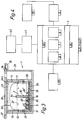
- FIGS. 1 to 3 which are shown in a highly simplified manner, a top view of a fermenter 1 has a rectangular shape, the width corresponding approximately to half the length of the rectangular shape.
- the fermenter 1, which is made of concrete, has a dividing wall 2 which is still to be specified and which extends indirectly from the inside 3 of one end wall 4 of the fermenter 1, but does not reach the opposite end wall 5, so that three zones 6, 7 , 8 result, which are used as heating zones, which will also be discussed in more detail.
- a manure channel 9 opens, which starts from a manure collecting channel 10 of a cattle shed.
- the end walls 4, 5 of the fermenter 1 and its side walls 11, 12 are provided with insulating plates 13, 14, 15 and 16, just as the bottom 17 is equipped with an insulating plate 18.
- This insulating plate 18 is covered with a screed 19, which is equipped with upstanding supports 20, on which heating coils 22, 23, 24 are provided separately from one another from a distributor 21, which enable zones 6, 7 and 8 to be tempered differently in a range of 30-39 ° C.
- nozzles 25 located beneath the heating coils 22, 23, 24, which are connected to pressure lines 26 carrying biogas provided in the screed 19 and the manure which has entered the fermenter 1 through the inlet 9 and whose mirror is dotted with a dot-dash line Line 27 is given, mix and intensify the fermentation process.
- the nozzles 25 have different distances in the individual zones 6, 7, 8, possibly also at the end of the fermentation path, and they are also arranged such that perfect and fermentation-appropriate circulation takes place in the individual temperature ranges.
- the discharge of the fermented liquid manure takes place in the vicinity of the fermenter end wall 4 at 28 (cf. in particular FIG. 3), the discharge opening into a pump-down container 29, which can be part of the fermenter, ie it can be made of concrete with the fermenter 1 consist. It is important that the partition 2 is inserted into the inside of the fermenter in such a way that the liquid manure entering the fermenter 1 through the inlet 9 cannot flow into the pumping container 29 without fermentation and must make a detour around the partition 2.
- the partition 2 is spanned by a relatively strong but flexible film hood 30, which on the walls 4, 5 and 11, 12 of the fermenter 1 with the interposition of the insulating plates 13 to 16 is fastened, the lower edge of the film hood 30 resulting in a gas reservoir extending far below the slurry level 27 (cf. 22, 23, 24).
- the attachment is done with dowels, as indicated by lines and small circles in Figures 1 and 3.
- the partition wall 2 which makes up 1/3 to 2/3 of the height of the fermenter 1, can also be designed to be variable in its effective height and length by fitting it into a U-shaped, attached to the fermenter end wall 4 and also the film hood 30 the insulating plate 13 engages pressing bracket 31 (not shown in Fig. 3) and can be moved to the left. It is understood that the holder 31 is designed so that no matter which position the partition 2 occupies, no fermented manure can get into the pumping chute 29. To secure the position of the partition 2, plug connections 32 to the screed 19 are conceivable, as is indicated in FIG. 2.
- an attachment piece can be attached, as can be seen by broken lines 33. Plug connections can also be used here, unless one provides a type of tongue and groove connection 34 - as shown in FIG. 3 - which also appears conceivable for the floor bracket.
- the partition 2 (see FIG. 3) could be made in one piece with the bottom 17 of the fermenter 1, but because of the dowelling of the film hood 30, the partition 2 must have a distance from the insulating plate 13 or the fermenter end wall 4 which is too is close, e.g. with sealing strips that act like the bracket 31.
- the fermenter 1, as can be seen in FIGS. 1 and 3, is let into the bottom 35, in such a way that the Cover 36, which cover fermenter 1, is flush with upper side 37 of base 35.
- the covers 36 are so strong or so reinforced that they can be driven over, that is to say that the fermenter 1 can be arranged practically in the middle of the courtyard of a farm estate without it interfering.
- the covers 36 are expediently also insulated, so that heat losses are virtually impossible.
- the pumping chute 29 is also equipped with a cover 38 that can be driven over.
- the film hood 30 is provided with at least one connection 39 in order to discharge the biogas to the units of the plant.
- the lines for the distributor 21 are routed underground, so that nothing can be seen of the fermenter 1 according to the invention, and even more so when the connector (s) 39 or their further lines do not emerge through an opening 40 in the cover 36, but instead are laid in channels.
- FIG. 5 shows the already mentioned biogas cooler 41, which is highly insulated and absorbs cooling liquid 43.
- a coiled tube 44 which represents an intermediate piece of the biogas line 45 shown in FIG. 7 between the fermenter 1 and the cogeneration unit 42.
- the actual cooling unit 46 is located in the center of the biogas cooler 41, which is not described in detail since it is a commodity.
- the tube coil 44 are designed so that there is always a slope for the drainage of the condensate.
- the part of a helix 44 shown in FIG. 6 and greatly enlarged compared to FIG. 5 reveals a braking section 47 which, although somewhat slows down the flow of the biogas by narrowing the cross section, does not hinder the complete drainage of the condensate if a slowdown also occurs here.
- This braking distance can be easily generated from the outside with a press tool.
- annular ribs 48 are provided, which could also run in a serpentine manner, as indicated by the broken line 49.
- Axial ribs 50 are also conceivable.
- a round cross-section is not mandatory, rather, e.g. Square tubes are used.
- a pollutant quantity and / or quality measuring device 52 is provided in the biogas line 45, between the biogas cooler 41 and the cogeneration 42, which contributes to the fact that the entire system can be operated in an environmentally friendly manner and with a high degree of efficiency.
- the latter mainly because there is still a type of gas meter 53 in the biogas line 45, which controls a uniform inflow of fresh manure from a storage container 55 into the manure channel 9 or into the fermenter 1 via a dashed line 54.
- the gas meter 53 controls a pump 57 via a dash-dotted control line 56, which is provided in a pumping line 58 connecting the removal point 29 to the slurry channel 9.
- control line 56 can also be connected to the pollutant quantity and / or quality measuring device 52 via a line 59, which is indicated by a -.- line. With 60 a small compressor is indicated, which serves for the metered introduction of air into the biogas line 45.
Landscapes
- Health & Medical Sciences (AREA)
- Life Sciences & Earth Sciences (AREA)
- Engineering & Computer Science (AREA)
- Chemical & Material Sciences (AREA)
- Zoology (AREA)
- Organic Chemistry (AREA)
- Bioinformatics & Cheminformatics (AREA)
- Wood Science & Technology (AREA)
- Biotechnology (AREA)
- Genetics & Genomics (AREA)
- General Engineering & Computer Science (AREA)
- Biochemistry (AREA)
- Sustainable Development (AREA)
- General Health & Medical Sciences (AREA)
- Microbiology (AREA)
- Biomedical Technology (AREA)
- Clinical Laboratory Science (AREA)
- Molecular Biology (AREA)
- General Chemical & Material Sciences (AREA)
- Oil, Petroleum & Natural Gas (AREA)
- Treatment Of Sludge (AREA)
- Apparatus Associated With Microorganisms And Enzymes (AREA)
- Processing Of Solid Wastes (AREA)
Applications Claiming Priority (4)
| Application Number | Priority Date | Filing Date | Title |
|---|---|---|---|
| DE4105841 | 1991-02-25 | ||
| DE4105841A DE4105841C1 (en) | 1991-02-25 | 1991-02-25 | Bio-gas prodn. from manure - in a plant with three fermentation zones |
| DE4143229 | 1991-12-31 | ||
| DE4143229A DE4143229A1 (de) | 1991-02-25 | 1991-12-31 | Anlage zur gewinnung von biogas aus guelle |
Publications (2)
| Publication Number | Publication Date |
|---|---|
| EP0501376A2 true EP0501376A2 (fr) | 1992-09-02 |
| EP0501376A3 EP0501376A3 (en) | 1993-01-13 |
Family
ID=25901324
Family Applications (1)
| Application Number | Title | Priority Date | Filing Date |
|---|---|---|---|
| EP19920103063 Withdrawn EP0501376A3 (en) | 1991-02-25 | 1992-02-24 | Plant for the production of biogas from manure |
Country Status (2)
| Country | Link |
|---|---|
| EP (1) | EP0501376A3 (fr) |
| DE (1) | DE4143229A1 (fr) |
Cited By (9)
| Publication number | Priority date | Publication date | Assignee | Title |
|---|---|---|---|---|
| DE19805580C1 (de) * | 1998-02-12 | 1999-09-16 | Matthias Beisler | Biogasfermenter |
| DE20104047U1 (de) * | 2000-07-14 | 2001-11-29 | BEKON Energy Technologies GmbH, 84032 Landshut | Bioreaktor zur Methanisierung von Biomasse und eine Biogasanlage zur Erzeugung von thermischer, elektrischer oder mechanischer Energie aus Biomasse mit einem solchen Bioreaktor |
| DE10034279A1 (de) * | 2000-07-14 | 2002-02-21 | Bekon Umweltschutz & Energiete | Bioreaktor zur Methanisierung von Biomasse, Biogasanlage zur Erzeugung von thermischer, elektrischer oder mechanischer Energie aus Biomasse sowie Verfahren zur Steuerung solcher Biogasanlagen |
| DE102006002836A1 (de) * | 2006-01-20 | 2007-07-26 | Eckard, Horst K. | Einleitung von Biogas in einen Fermenter |
| DE102008038065A1 (de) * | 2008-08-16 | 2010-02-18 | Rajib Pal Chowdhury | Biogasanlagen-Fermenter |
| DE102009032122A1 (de) * | 2009-07-08 | 2011-01-13 | Robert Bosch Gmbh | Verfahren und Vorrichtung zur Energiegewinnung aus Biomasse und Biogasanlage |
| WO2013039407A1 (fr) | 2011-09-16 | 2013-03-21 | Green Gas As | Système modulaire de digestion anaérobie |
| FR3045663A1 (fr) * | 2015-12-22 | 2017-06-23 | Biogaz Pevele | Unite de methanisation equipee d'un digesteur lineaire en forme de " u " avec echangeur thermique interne |
| CN113462439A (zh) * | 2021-05-25 | 2021-10-01 | 华北水利水电大学 | 一种化粪池气体处理及利用装置 |
Families Citing this family (5)
| Publication number | Priority date | Publication date | Assignee | Title |
|---|---|---|---|---|
| DE19908351A1 (de) * | 1999-02-26 | 2000-09-07 | En Of Nature Projektgesellscha | Verfahren und Einrichtung zur Bereitstellung von Biogas |
| DE10254309A1 (de) * | 2002-11-21 | 2004-06-17 | Ostendorf, Joseph | Vorrichtung und Verfahren zur Erzeugung von Biogas |
| DE102005026587A1 (de) * | 2005-05-27 | 2006-11-30 | Kaufmann, Jürgen | Verfahren und Vorrichtung zur Aufbereitung von Biogas oder Faulgas |
| DE102005053345A1 (de) * | 2005-11-07 | 2007-05-10 | Me-Thie-Supergas Gmbh & Co. Kg | Verfahren zum Aufbereiten eines brennbaren Gases biologischen Ursprungs und Vorrichtung zum Durchführen des Verfahrens |
| DE102012218956A1 (de) * | 2012-10-17 | 2014-04-17 | Edwin Bailer | Gasreinigungsvorrichtung |
Family Cites Families (3)
| Publication number | Priority date | Publication date | Assignee | Title |
|---|---|---|---|---|
| FR2376209A1 (fr) * | 1977-01-04 | 1978-07-28 | Maumont Amaury | Procede et dispositifs pour la production et le stockage du gaz de fermentation de dechets cellulosiques |
| DE3151187C2 (de) * | 1981-12-23 | 1986-02-20 | Günther 7920 Heidenheim Hof | Biogas-Anlage |
| FR2531601A1 (fr) * | 1982-08-12 | 1984-02-17 | Aisne Chambre Agriculture | Procede et installation de production de biogaz a partir d'un effluent liquide organique, tel que par exemple le lisier et echangeur thermique comme moyen necessaire pour la mise en oeuvre dudit procede ou de ladite installation |
-
1991
- 1991-12-31 DE DE4143229A patent/DE4143229A1/de not_active Withdrawn
-
1992
- 1992-02-24 EP EP19920103063 patent/EP0501376A3/de not_active Withdrawn
Cited By (9)
| Publication number | Priority date | Publication date | Assignee | Title |
|---|---|---|---|---|
| DE19805580C1 (de) * | 1998-02-12 | 1999-09-16 | Matthias Beisler | Biogasfermenter |
| DE20104047U1 (de) * | 2000-07-14 | 2001-11-29 | BEKON Energy Technologies GmbH, 84032 Landshut | Bioreaktor zur Methanisierung von Biomasse und eine Biogasanlage zur Erzeugung von thermischer, elektrischer oder mechanischer Energie aus Biomasse mit einem solchen Bioreaktor |
| DE10034279A1 (de) * | 2000-07-14 | 2002-02-21 | Bekon Umweltschutz & Energiete | Bioreaktor zur Methanisierung von Biomasse, Biogasanlage zur Erzeugung von thermischer, elektrischer oder mechanischer Energie aus Biomasse sowie Verfahren zur Steuerung solcher Biogasanlagen |
| DE102006002836A1 (de) * | 2006-01-20 | 2007-07-26 | Eckard, Horst K. | Einleitung von Biogas in einen Fermenter |
| DE102008038065A1 (de) * | 2008-08-16 | 2010-02-18 | Rajib Pal Chowdhury | Biogasanlagen-Fermenter |
| DE102009032122A1 (de) * | 2009-07-08 | 2011-01-13 | Robert Bosch Gmbh | Verfahren und Vorrichtung zur Energiegewinnung aus Biomasse und Biogasanlage |
| WO2013039407A1 (fr) | 2011-09-16 | 2013-03-21 | Green Gas As | Système modulaire de digestion anaérobie |
| FR3045663A1 (fr) * | 2015-12-22 | 2017-06-23 | Biogaz Pevele | Unite de methanisation equipee d'un digesteur lineaire en forme de " u " avec echangeur thermique interne |
| CN113462439A (zh) * | 2021-05-25 | 2021-10-01 | 华北水利水电大学 | 一种化粪池气体处理及利用装置 |
Also Published As
| Publication number | Publication date |
|---|---|
| EP0501376A3 (en) | 1993-01-13 |
| DE4143229A1 (de) | 1993-07-01 |
Similar Documents
| Publication | Publication Date | Title |
|---|---|---|
| EP0501376A2 (fr) | Installation pour la production de biogaz à partir de purin | |
| DE3007256C2 (fr) | ||
| DE2725239A1 (de) | Waermeaustauschsystem und metalltafel fuer ein waermeaustauschsystem | |
| DE1925234A1 (de) | Indirekte Luftkondensationsanlage | |
| DE2250794A1 (de) | Kondensationseinrichtung fuer dampfturbinenkraftwerke | |
| DE2535581A1 (de) | Sonnenenergie-kollektor | |
| DE102019134349A1 (de) | Gebäudesystem zur Klimatisierung und Wärmeversorgung | |
| DE19804007A1 (de) | Verfahren und Vorrichtung zur biologischen Behandlung eines organisch belasteten Fluids unter Biogasgenerierung | |
| DE2804748B1 (de) | Waerme-isolierter Behaelter fuer warmes Wasser o.a. Fluessigkeiten | |
| DE2501796C2 (fr) | ||
| DE102010052446A1 (de) | Vorrichtung zum Verhindern des Entstehens von seewasserbedingten Ablagerungen | |
| DE4105841C1 (en) | Bio-gas prodn. from manure - in a plant with three fermentation zones | |
| EP0141339B1 (fr) | Dispositif pour la récupération de la chaleur des eaux usées avec économie simultanée d'eau potable | |
| DE19707859A1 (de) | Anordnung zur Übertragung von Wärmeenergie | |
| EP0092251A2 (fr) | Dispositif pour la conversion d'énergie solaire en chaleur | |
| DE102011008762B4 (de) | Anlage zum Erwärmen von Trinkwasser und zum Abtöten von Legionellen und sonstigen Keimen in dem Trinkwasser | |
| DE4020990A1 (de) | Abgas-luft-waermetauscher fuer eine brennkraftmaschine | |
| EP2479502B1 (fr) | Installation et procédé d'utilisation énergétique de fluides disponibles dans des récipients de collecte d'eaux usées et/ou de récipients de traitement d'eaux usées | |
| DE2939827A1 (de) | Waermetauscher, insbesondee zur verwertung von abluftwaerme | |
| DE19542076A1 (de) | Warmwasserspeicher, insbesondere für Brauchwasser | |
| DE4315864C2 (de) | Anordnung zum Wärmeaustausch | |
| DE3409480A1 (de) | Verfahren zur kaelteerzeugung mit zwischengeschaltetem kaeltespeicher zur versorgung lufttechnischer anlagen od. dgl. und anlagen zur durchfuehrung des verfahrens | |
| DE4215847C2 (de) | Verfahren und Anlage zum Kompostieren | |
| DE3014546A1 (de) | Vorichtung zur nutzung von umgebungsenergie | |
| DE2237757A1 (de) | Verfahren und vorrichtung zur klimatisierung von raeumen |
Legal Events
| Date | Code | Title | Description |
|---|---|---|---|
| PUAI | Public reference made under article 153(3) epc to a published international application that has entered the european phase |
Free format text: ORIGINAL CODE: 0009012 |
|
| AK | Designated contracting states |
Kind code of ref document: A2 Designated state(s): AT BE CH DE DK ES FR GB GR IT LI LU MC NL PT SE |
|
| PUAL | Search report despatched |
Free format text: ORIGINAL CODE: 0009013 |
|
| AK | Designated contracting states |
Kind code of ref document: A3 Designated state(s): AT BE CH DE DK ES FR GB GR IT LI LU MC NL PT SE |
|
| 17P | Request for examination filed |
Effective date: 19930708 |
|
| STAA | Information on the status of an ep patent application or granted ep patent |
Free format text: STATUS: THE APPLICATION IS DEEMED TO BE WITHDRAWN |
|
| 18D | Application deemed to be withdrawn |
Effective date: 19950901 |