EP0501385A1 - Rahmen besonders für Fahrräder - Google Patents
Rahmen besonders für Fahrräder Download PDFInfo
- Publication number
- EP0501385A1 EP0501385A1 EP92103075A EP92103075A EP0501385A1 EP 0501385 A1 EP0501385 A1 EP 0501385A1 EP 92103075 A EP92103075 A EP 92103075A EP 92103075 A EP92103075 A EP 92103075A EP 0501385 A1 EP0501385 A1 EP 0501385A1
- Authority
- EP
- European Patent Office
- Prior art keywords
- pair
- beam member
- frame according
- support
- slots
- Prior art date
- Legal status (The legal status is an assumption and is not a legal conclusion. Google has not performed a legal analysis and makes no representation as to the accuracy of the status listed.)
- Withdrawn
Links
Images


Classifications
-
- B—PERFORMING OPERATIONS; TRANSPORTING
- B62—LAND VEHICLES FOR TRAVELLING OTHERWISE THAN ON RAILS
- B62K—CYCLES; CYCLE FRAMES; CYCLE STEERING DEVICES; RIDER-OPERATED TERMINAL CONTROLS SPECIALLY ADAPTED FOR CYCLES; CYCLE AXLE SUSPENSIONS; CYCLE SIDECARS, FORECARS, OR THE LIKE
- B62K13/00—Cycles convertible to, or transformable into, other types of cycles or land vehicle
- B62K13/08—Frames
Definitions
- the present invention relates to a frame particularly usable for bicycles and in particular for bicycles for undertaking excursions in the mountains or on rough terrain, also known as "mountain bikes”.
- the aim of the present invention is therefore to eliminate the problems described above in known types of bicycle by providing a frame which allows the user to practice in an optimum manner various sports, such as uphill racing, downhill racing, cross-country racing and parallel slalom.
- an important object is to provide a frame which can be adapted according to the specific sports practice required by the user.
- Another object is to provide a frame which associates with the preceding characteristics that of being adaptable to the specific build of the user.
- Still another object is to provide a frame in which said modifications can be performed rapidly and easily by the user.
- a further object is to provide a frame which is structurally simple and can be manufactured with conventional facilities and known machinery.
- Another important object is to provide a frame which allows to limit the cost of equipment, in particular of the dies for obtaining the various frame sizes.
- Not a least object is to provide a frame which associates with the preceding characteristics that of being reliable and safe in use.
- a frame particularly for bicycles, which is characterized in that it comprises a single-beam member which has one or more seats for means for temporarily engaging and adjusting the position of at least one support for the saddle and/or for a pedal crank assembly and/or for a derailleur and/or for the hubs of the rear and/or front wheels and/or for the handlebar.
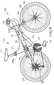
- the reference numeral 1 designates a bicycle in which there is a frame 2 which comprises a single-beam member 3.
- Said single-beam member preferably has an elliptical cross-section and is connected, at its ends, by known means, to a sleeve 4 with which a handlebar 5 and a pair of forks 6 are associated; the hub of the front wheel 7 is associable with the ends of said forks 6.
- the single-beam member 3 can be connected, by known means, at a derailleur 8 and at a rear wheel 9.
- the frame is furthermore constituted by a first support 10 for the sleeve 11 for coupling to a saddle 12 and by a second support 13 for a pedal crank assembly 14.
- the first support 10 is essentially V-shaped and is thus constituted by a first pair of arms 15 directed toward the handlebar 5 and by a second pair of arms 16 which are directed toward the rear wheel 9.
- First and second means for temporary engagement with the single-beam member 3, designated by the numerals 17 and 18, are provided respectively at the ends of the first pair of arms and of the second pair of arms.
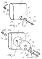
- Said first engagement means can be constituted, as illustrated in figure 3, by a pair of sliders 19 which can slide at adapted guides, designated by the numerals 20a and 20b, which are defined in the upper region of the single-beam member 3 proximate to the handlebar 5.
- First longitudinal slots 21 are defined at the pair of sliders 19 and are thus arranged approximately along an axis which is parallel to the longitudinal axis of the single-beam member 3.
- Said second engagement means 18 can be constituted, as shown in figure 2, by a pair of wings 22 which are arranged along an axis which is approximately perpendicular to the longitudinal axis of the single-beam member 3.
- a second slot 23 is defined at each of said pairs of wings 22, longitudinally thereto.
- Said wing can be arranged in a region adjacent to a pair of shoulders 24 which protrude laterally with respect to the upper perimetric edge 25 of the single-beam member in a region which is adjacent to the rear wheel 9.
- Each of said pairs of shoulders 24, which are mutually parallel, is provided with a third slot 26 which is arranged along an axis which is approximately parallel to the longitudinal axis of the single-beam member 3.
- the first and second temporary engagement means interact respectively with first adjustment means 27 and with second adjustment means 28 which can be constituted, as shown in figures 2 and 3, by a pair of screws, designated by the numerals 29a and 29b, the stems whereof can be inserted, by means of the interposition of one or more possible first washers 30a and 30b, respectively at the first slot 21 and at the second slot 23.
- the stem of the screw 29a furthermore passes through an adapted first hole 31 which is defined at the shoulder 32 of the single-beam member 3, said shoulder being defined by the pair of guides 20a and 20b.
- stems of the pair of screws 29a and 29b affect both sliders 19 and both wings 22 and are coupled, by means of the interposition of possible second washers 33a and 33b, to a pair of complementarily threaded first bushes 34a and 34b, each of which is provided with a first grip handle for the user, designated by the numerals 35a and 35b.
- the user can vary the position of the first support 10 and thus of the saddle 12: in fact, once said pairs of bushes have been loosened, it is possible to shift the position of the saddle 12 forward or backward according to the specific sports practice chosen.
- the second support 13 for the pedal crank assembly 14 is also preferably constituted by a pair of third and fourth arms, respectively designated by the numerals 36 and 37.
- Said arms are mutually connected at the pedal crank assembly 14 and both have, at their free end, respectively a pair of mutually facing first and second cylindrical pins, each pair being designated by the numerals 38 and 39.
- Said first and second cylindrical pins constitute respectively third and fourth means for coupling to the single-beam member 3.
- Each of said pins in fact has a second axial hole, designated by the numerals 40a and 40b.
- first cylindrical pins are rotatably associated at complementarily shaped first seats 41 which are axially perforated and are defined eccentrically with respect to a pair of disks 42 which can be arranged at complementarily shaped second seats 43 defined at the lateral surfaces 44 of the single-beam member 3.
- Each disk of said pair of disks 42 and each of said second seats 43 has a third hole 45 and a fourth hole 46 which have the same axis.
- the facing ends of the second cylindrical pins 39 are rotatably associable at complementarily shaped third seats 47 which are axially perforated and are defined at the single-beam member 3 in a region which is adjacent to the pair of shoulders 24 and proximate to the lower perimetric edge 48 of said single-beam member 3.
- connection between the first cylindrical pins 38 of the third pair of arms 36 and the pair of disks 42 is achieved by a pair of second screws 49, the threaded stem whereof engages the complementarily threaded hole defined axially with respect to the first seats 41.
- the frame furthermore comprises third and fourth means for adjusting the position of the second support 13 with respect to the single-beam member 3; said third and fourth adjustment means are constituted by a third pair of screws 50a and 50b, the threaded stems whereof are inserted, with the possible interposition of third washers 51a and 51b, in the third hole 45 of a disk 42 and then in the fourth hole 46 of the second disk of the pair of disks 42 and are then secured, with the possible interposition of fourth washers 52a and 52b, to a pair of second complementarily threaded bushes 53a and 53b which have adapted second pairs of handles 54a and 54b.
- third and fourth adjustment means are constituted by a third pair of screws 50a and 50b, the threaded stems whereof are inserted, with the possible interposition of third washers 51a and 51b, in the third hole 45 of a disk 42 and then in the fourth hole 46 of the second disk of the pair of disks 42 and are then secured, with the possible interposition of fourth washers 52a
- the second support 13 allows to adjust the height of the pedal crank assembly 14 from the ground: in fact, once the pair of second bushes 53a and 53b has been loosened, the user can vary the position of the first cylindrical pin 38 and thus of the third pair of arms 36, forcing the rotation of the pair of disks 42.
- the eccentricity of the pivoting of the first cylindrical pins 38 to the pair of disks 42 in fact allows to gradually vary the position of said first cylindrical pins 38 with respect to the ground.
- the frame can be used for all the various specialties of mountain biking, adopting an optimum configuration for each of them.
- the presence of the means for temporarily engaging the first and second supports and for adjusting their position with respect to the single-beam member allows to vary the position of the first support 10 and thus of the saddle 12, so as to be able to move said saddle toward the rear wheel or toward the front wheel and at the same time vary the position of the pedal crank assembly with respect to the ground.
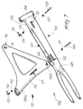
- figures 6 and 7 illustrate a second embodiment for a bicycle 101 which comprises a frame 102 which comprises a single-beam member 103 which is connected, at its end, to the sleeve 104 for a handlebar 105 with which a pair of forks 106 for connecting a hub of the front wheel 107 is associated, while the single-beam member 103 is associated, at its other end, with a possible derailleur 108 and with a rear wheel 109.
- the frame 102 is furthermore constituted by a single support 110 which is essentially shaped like an isosceles triangle, which has a slightly arc-like base 155 directed toward the rear wheel 109 and the vertex 156 opposite thereto directed toward the sleeve 104.
- Said support 110 can be inserted in an adapted opening 157 which is defined longitudinally with respect to the single-beam member 103 along a plane which passes through the upper and lower perimetric edges 125 and 148.
- a first hole 131 is defined at the vertex 156 and can be arranged at a pair of first slots 121 defined longitudinally with respect to the single-beam member 103 at 144 and proximate to the sleeve 104.
- a space such as to accommodate the vertex 156 of the first support 110 is in any case defined at the first slots 121.
- the frame 102 furthermore comprises a first screw 129 which, with the interposition of a possible first washer 130, is caused to pass through the first slots 121, passing through the first hole 131 of the support 110 as well.
- a first bush 134 is associable with the first screw 129, with the possible interposition of a second washer 133, and is provided with an adapted handle 135 which can be operated by the user.
- Second slots 123 are furthermore defined at the base 155 of the support 110 and may be slightly curved with respect to said base, so as to define a concavity toward the first slots 121.
- the second slots 123 arrange themselves so that they face a pair of third slots 126 defined longitudinally to the single-beam member 103.
- the locking of the position of the support 110 is allowed by the presence of a second screw 149 the stem whereof is passed, possibly with the interposition of a third washer 151, through the third slots 126 and at the same time through the second slots 123 and is then secured, with the possible interposition of a fourth washer 152, to a second bush 153 which has a grip handle 154 for the user.
- an adapted thread is provided at the end 158a of the base 155 in order to secure a saddle 112, whereas the execution of an adapted second hole 140 is provided for at the end 158b in order to associate an adapted pedal crank assembly 114 with the support 110.
- the materials and the dimensions of the individual components of the structure may also naturally be the most adapted according to the specific requirements.
Landscapes
- Engineering & Computer Science (AREA)
- Mechanical Engineering (AREA)
- Automatic Cycles, And Cycles In General (AREA)
Applications Claiming Priority (2)
| Application Number | Priority Date | Filing Date | Title |
|---|---|---|---|
| ITTV910024 | 1991-02-27 | ||
| ITTV910024A IT1247366B (it) | 1991-02-27 | 1991-02-27 | Struttura di telaio particolarmente per cicli |
Publications (1)
| Publication Number | Publication Date |
|---|---|
| EP0501385A1 true EP0501385A1 (de) | 1992-09-02 |
Family
ID=11418813
Family Applications (1)
| Application Number | Title | Priority Date | Filing Date |
|---|---|---|---|
| EP92103075A Withdrawn EP0501385A1 (de) | 1991-02-27 | 1992-02-24 | Rahmen besonders für Fahrräder |
Country Status (2)
| Country | Link |
|---|---|
| EP (1) | EP0501385A1 (de) |
| IT (1) | IT1247366B (de) |
Cited By (7)
| Publication number | Priority date | Publication date | Assignee | Title |
|---|---|---|---|---|
| FR2718703A1 (fr) * | 1994-04-14 | 1995-10-20 | Nard Gilles | Bicyclette à pédalier déplaçable. |
| DE29704203U1 (de) * | 1997-03-10 | 1997-07-17 | Interco Gesellschaft für Planung und Vertrieb von Rehabilitationshilfen mbH, 53783 Eitorf | Behindertenfahrrad |
| DE19744118A1 (de) * | 1997-10-06 | 1999-04-08 | Matthias Frerck | Tretkurbeleinheit für Fahrräder oder dergleichen in Tauschkassette |
| DE10032787A1 (de) * | 2000-04-17 | 2001-10-25 | Continental Eng Syst Ltd | Ein neuer Allzweck-Fahrradrahmen |
| US8002347B2 (en) | 2007-10-23 | 2011-08-23 | Geyer James B | Cycle seat with adjustable sides |
| WO2017006090A3 (en) * | 2015-07-03 | 2017-02-16 | Jennock Limited | An adjustably sized bicycle frame |
| USD931759S1 (en) | 2018-01-04 | 2021-09-28 | Jennock Limited | Bicycle frame |
Citations (6)
| Publication number | Priority date | Publication date | Assignee | Title |
|---|---|---|---|---|
| GB194012A (en) * | 1921-12-12 | 1923-03-08 | Ernest Douglas Field | Improvements in children's scooters, cycles, velocipedes and the like |
| FR2422545A1 (fr) * | 1978-01-12 | 1979-11-09 | Nouacer Driss | Bicyclette et tandem modulaires |
| EP0163988A2 (de) * | 1984-05-25 | 1985-12-11 | PAIOLI S.p.A. | Fahrradrahmen mit abänderungsfähigem Aufbau |
| US4909537A (en) * | 1989-03-06 | 1990-03-20 | Tratner Alan A | Universal vehicle for pedaling or the like |
| DE3837018A1 (de) * | 1988-10-31 | 1990-05-10 | Reinhard Docter | Variables steh-liegefahrrad |
| US5072961A (en) * | 1990-07-09 | 1991-12-17 | Huppe Dennis P | Bicycle with universal adjustable frame |
-
1991
- 1991-02-27 IT ITTV910024A patent/IT1247366B/it active IP Right Grant
-
1992
- 1992-02-24 EP EP92103075A patent/EP0501385A1/de not_active Withdrawn
Patent Citations (6)
| Publication number | Priority date | Publication date | Assignee | Title |
|---|---|---|---|---|
| GB194012A (en) * | 1921-12-12 | 1923-03-08 | Ernest Douglas Field | Improvements in children's scooters, cycles, velocipedes and the like |
| FR2422545A1 (fr) * | 1978-01-12 | 1979-11-09 | Nouacer Driss | Bicyclette et tandem modulaires |
| EP0163988A2 (de) * | 1984-05-25 | 1985-12-11 | PAIOLI S.p.A. | Fahrradrahmen mit abänderungsfähigem Aufbau |
| DE3837018A1 (de) * | 1988-10-31 | 1990-05-10 | Reinhard Docter | Variables steh-liegefahrrad |
| US4909537A (en) * | 1989-03-06 | 1990-03-20 | Tratner Alan A | Universal vehicle for pedaling or the like |
| US5072961A (en) * | 1990-07-09 | 1991-12-17 | Huppe Dennis P | Bicycle with universal adjustable frame |
Cited By (11)
| Publication number | Priority date | Publication date | Assignee | Title |
|---|---|---|---|---|
| FR2718703A1 (fr) * | 1994-04-14 | 1995-10-20 | Nard Gilles | Bicyclette à pédalier déplaçable. |
| DE29704203U1 (de) * | 1997-03-10 | 1997-07-17 | Interco Gesellschaft für Planung und Vertrieb von Rehabilitationshilfen mbH, 53783 Eitorf | Behindertenfahrrad |
| DE19744118A1 (de) * | 1997-10-06 | 1999-04-08 | Matthias Frerck | Tretkurbeleinheit für Fahrräder oder dergleichen in Tauschkassette |
| DE10032787A1 (de) * | 2000-04-17 | 2001-10-25 | Continental Eng Syst Ltd | Ein neuer Allzweck-Fahrradrahmen |
| US8002347B2 (en) | 2007-10-23 | 2011-08-23 | Geyer James B | Cycle seat with adjustable sides |
| WO2017006090A3 (en) * | 2015-07-03 | 2017-02-16 | Jennock Limited | An adjustably sized bicycle frame |
| CN108349563A (zh) * | 2015-07-03 | 2018-07-31 | 震诺克有限公司 | 一种可调节尺寸的自行车车架 |
| JP2018524230A (ja) * | 2015-07-03 | 2018-08-30 | ジェンノック リミテッド | 調整可能にサイズ決めされた自転車フレーム |
| CN108349563B (zh) * | 2015-07-03 | 2020-05-08 | 震诺克有限公司 | 一种可调节尺寸的自行车车架 |
| US10870458B2 (en) | 2015-07-03 | 2020-12-22 | Jennock Limited | Adjustably sized bicycle frame |
| USD931759S1 (en) | 2018-01-04 | 2021-09-28 | Jennock Limited | Bicycle frame |
Also Published As
| Publication number | Publication date |
|---|---|
| IT1247366B (it) | 1994-12-12 |
| ITTV910024A0 (it) | 1991-02-27 |
| ITTV910024A1 (it) | 1992-08-27 |
Similar Documents
| Publication | Publication Date | Title |
|---|---|---|
| US5138900A (en) | Adjustable handlebar stem for a bicycle or similar vehicle | |
| US11052964B2 (en) | Bicycle frame assembly | |
| EP1340674B1 (de) | Pedalvorrichtung für Fahrräder | |
| US5033325A (en) | Adjustable connection for bicycle handlebar | |
| EP2964514B1 (de) | Kinderfahrrad | |
| US5273302A (en) | Adjustable bicycle stem | |
| JP2008518826A (ja) | 取り外し可能でありかつ調節可能なエアロバーを備える自転車ハンドルバー | |
| US5752711A (en) | Bicycle | |
| JP6666366B2 (ja) | 調整可能にサイズ決めされた自転車フレーム | |
| EP1671881B1 (de) | Hinterradkettenschaltung für ein Fahrrad | |
| EP1167173B1 (de) | Fahrradpedal | |
| EP1877300B1 (de) | Lenkerverlängerung | |
| US6863142B2 (en) | Motorcycle traction accessory device | |
| US8857822B1 (en) | Methods of biking or cycling on varied surfaces | |
| US5555775A (en) | Bicycle handlebars | |
| CA2285892A1 (en) | Cycleski | |
| RU2242152C2 (ru) | Шип велотуфли для разъемного крепления туфли к педали велосипеда | |
| US5284351A (en) | Recumbent bicycle | |
| RU2232693C2 (ru) | Узел педали велосипеда | |
| CA2233696C (en) | Dual seat two wheel drive bicycle | |
| FR2719279A1 (fr) | Perfectionnements à une bicyclette à pédalier déplaçable. | |
| FR2762282A1 (fr) | Velo tout terrains et tous temps pour personnes handicapees physiques | |
| FR2608123A1 (fr) | Bicyclette a double systeme de propulsion | |
| WO2022099177A1 (en) | Steering linkage for bicycles | |
| CA2129598A1 (en) | Bicycle |
Legal Events
| Date | Code | Title | Description |
|---|---|---|---|
| PUAI | Public reference made under article 153(3) epc to a published international application that has entered the european phase |
Free format text: ORIGINAL CODE: 0009012 |
|
| AK | Designated contracting states |
Kind code of ref document: A1 Designated state(s): DE IT |
|
| STAA | Information on the status of an ep patent application or granted ep patent |
Free format text: STATUS: THE APPLICATION IS DEEMED TO BE WITHDRAWN |
|
| 18D | Application deemed to be withdrawn |
Effective date: 19930303 |