EP0501502A2 - Verbinder mit niedriger Einsteck-/Rückziehkraft - Google Patents
Verbinder mit niedriger Einsteck-/Rückziehkraft Download PDFInfo
- Publication number
- EP0501502A2 EP0501502A2 EP92103441A EP92103441A EP0501502A2 EP 0501502 A2 EP0501502 A2 EP 0501502A2 EP 92103441 A EP92103441 A EP 92103441A EP 92103441 A EP92103441 A EP 92103441A EP 0501502 A2 EP0501502 A2 EP 0501502A2
- Authority
- EP
- European Patent Office
- Prior art keywords
- cam
- housings
- lock
- pair
- cam member
- Prior art date
- Legal status (The legal status is an assumption and is not a legal conclusion. Google has not performed a legal analysis and makes no representation as to the accuracy of the status listed.)
- Granted
Links
- 238000003780 insertion Methods 0.000 title claims description 18
- 230000037431 insertion Effects 0.000 title claims description 18
- 230000002265 prevention Effects 0.000 claims description 2
- 238000010276 construction Methods 0.000 description 5
- 238000000034 method Methods 0.000 description 3
- 230000000717 retained effect Effects 0.000 description 3
- 230000002093 peripheral effect Effects 0.000 description 2
- 238000007689 inspection Methods 0.000 description 1
- 230000013011 mating Effects 0.000 description 1
- 238000012986 modification Methods 0.000 description 1
- 230000004048 modification Effects 0.000 description 1
- 230000005405 multipole Effects 0.000 description 1
- 229920003002 synthetic resin Polymers 0.000 description 1
- 239000000057 synthetic resin Substances 0.000 description 1
Images




Classifications
-
- H—ELECTRICITY
- H01—ELECTRIC ELEMENTS
- H01R—ELECTRICALLY-CONDUCTIVE CONNECTIONS; STRUCTURAL ASSOCIATIONS OF A PLURALITY OF MUTUALLY-INSULATED ELECTRICAL CONNECTING ELEMENTS; COUPLING DEVICES; CURRENT COLLECTORS
- H01R13/00—Details of coupling devices of the kinds covered by groups H01R12/70 or H01R24/00 - H01R33/00
- H01R13/62—Means for facilitating engagement or disengagement of coupling parts or for holding them in engagement
- H01R13/629—Additional means for facilitating engagement or disengagement of coupling parts, e.g. aligning or guiding means, levers, gas pressure electrical locking indicators, manufacturing tolerances
- H01R13/62905—Additional means for facilitating engagement or disengagement of coupling parts, e.g. aligning or guiding means, levers, gas pressure electrical locking indicators, manufacturing tolerances comprising a camming member
Definitions
- This invention relates to an improved low insertion/withdrawal-force connector in which female and male housings can be fitted together and disengaged from each other by a cam member with a small force.
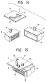
- a connector of this type as shown in Figs. 14 and 15 is proposed in Japanese Utility Model Application (OPI) No. Hei. 1-88474.
- OPI Japanese Utility Model Application
- a rotation shaft a2 is formed on a hood a1 of a female housing a
- a cam follower b1 is formed on a male housing b .
- An operating member c has a hole c2 serving as an axis of rotation of a rotation plate c1, and a cam groove c3. Using a rotation moment of the member c , the insertion and withdrawal of the male housing b relative to the female housing a can be done easily with a smaller force.
- the operating member c is of such a construction that it can be easily removed at any point during the time from the start to the end of the fitting operation. Therefore, there is a possibility that the operating member c may be inadvertently removed when the female and male housings a and b are still in an incompletely-fitted condition. Moreover, it is difficult to judge at a glance whether or not the fitting is complete. Furthermore, each time the fitting operation is finished, the operating member c is removed, and this increases the number of operation steps when a number of connectors are to undergo the fitting operation. Therefore, the assembling time and the labor cost are increased.
- the present invention has been made in view of the above problems, and an object of the invention is to provide a low insertion/withdrawal-force connector in which a cam member will never be disengaged during a fitting operation of female and male housings, and the cam member does not need to be removed when the housings are completely fitted together, and whether or not the fitting condition is good can be judged at a glance, and the complete fitting is ensured, and a compact construction can be achieved.
- a low insertion/withdrawal-force connector comprises: a cam member including cam grooves which are continuous respectively with introduction grooves, are provided at a lower surface of a rotation plate, and are disposed symmetrically with respect to a rotation shaft, and a rotation retaining plate provided at a distal end of the rotation shaft; a pair of housings which are fitted together and disengaged from each other by angularly moving the cam member, the two housings having cam follower pins, respectively, which are engaged in the two cam grooves of the cam member, respectively, one of the pair of housings having a pin guide groove which guides the cam follower pin of the other housing and the rotation shaft of the cam member, wherein when the cam member is angularly moved in an initial fitting condition of the pair of housings in which the cam follower pins of the housings are engaged respectively in the pair of cam grooves, the cam member moves toward an inner end of the pin guide groove, and also the pair of housings are moved toward each other toward
- an angular movement-effecting thumbpiece is withdrawably or slidably mounted on an upper surface of the rotation plate, and lock member is provided between the one housing and the thumbpiece so as to lock the thumbpiece when the pair of housings are completely fitted together.
- the pair of housings are moved each other toward the rotation shaft, and therefore the operation can be carried out smoothly.
- the rotation shaft moves along the pin guide groove.
- the rotation plate constituting the cam member has the flexible lock member, and unless the engagement of the flexible lock member is released by the initial fitting relative to the mating housing, the cam member can not be angularly moved, and also unless the complete fitting is achieved, the cam member can not be locked.
- the angular movement-effecting thumbpiece which is withdrawably or slidably mounted on the rotation plate constituting the cam member, and this thumbpiece can not be locked unless the complete fitting is achieved.
- the cam member can not be removed, and also the thumbpiece can not be locked. Therefore, the complete fitting is promoted, and an incomplete fitting is prevented. Further, there is no need to remove the cam member when the fitting is completed, and the number of the operation steps is reduced, and whether the cam member exists or not can be judged at a glance at an inspection step or the like, and whether the fitting condition of the connector is good or not can be judged easily and properly.
- reference character A denotes a female housing of a synthetic resin
- reference character B a male housing
- reference character C a cam member for fitting and disengaging the two housings relative to each other.
- Male terminals 7 and female terminals 11 are received respectively in terminal receiving chambers 1 and 8 of the pair of female and male housings A and B constituting a connector.
- the female housing A includes a housing body A1 having a plurality of terminal receiving chambers 1, and a hood A2 formed forwardly of this housing body so as to receive the male housing B.
- a retaining portion 2, serving as a lock means for the male housing B, is formed on one end wall of the hood A2.
- a cam follower pin 3 is formed on one of opposed longitudinal side walls of the female housing A at a lower central portion thereof, and a pin guide groove 4 is formed through this side wall, and is disposed above the pin 3.
- the pin guide groove 4 is open to the end edge of the hood A2, and extends in the direction of fitting of the male housing B. An end 4a of this pin guide groove reaches a recess A3 in the housing body A1. Provisionally-retaining projections 5 for the male housing B are provided at the inlet of the groove 4, and provisionally-retaining projections 6 are provided at the intermediate portion of this groove.
- a cam follower pin 10 corresponding to the cam follower pin 3 is formed on one of opposed side walls of the male housing at a lower portion thereof (the fitting side).
- the cam member C comprises a circular rotation plate 12, and an angular movement-effecting thumbpiece 16 which is formed on an outer surface of the rotation plate and extends transversely through the center thereof.
- a rotation shaft 13 is formed on the inner surface of the rotation plate 12 at the center thereof, and a rotation retaining plate 14 is formed on the distal end of this rotation shaft.
- Cam grooves 15 and 15 are formed in the inner surface of the rotation plate 12 symmetrically with respect to the rotation shaft 13, the cam grooves having introduction grooves 15 and 15' which are disposed at upper and lower portions, respectively, and extend parallel to a diametrical line perpendicularly intersecting the thumbpiece 16.
- Each of the cam grooves 15 and 15' is formed along an oval curved line in such a manner that the distance of the cam groove from the rotation shaft 13 of the rotation plate 12 is continuously varied, and its inner end portion 15b is the nearest to the rotation shaft 13 whereas its inlet portion (the introduction groove 15a) is the remotest therefrom.
- the distance between the inner ends 15b and 15b of the two cam grooves is so determined that this distance is equal to the distance between the cam follower pins 3 and 10 when the female and male housings A and B are completely fitted together.
- its diameter D1 is sufficiently larger than the width D2 of the pin guide groove 4 so that the rotation retaining plate will not become disengaged from the pin guide groove.
- An opening 17 is provided at the outer end portion of the introduction groove 15a of one cam groove 15 of the rotation plate 12, and a flexible lock member 18 is received in this opening so as to be resiliently displaced therein.
- the opening 17 perpendicularly intersects the introduction groove 15a, and is open in a direction away from the cam groove 15.
- the flexible lock member 18 includes a flexible tongue 18a of the cantilever type which extends toward the introduction groove 15a and has a fulcrum O at one end of the opening 17, a lock piece 18b projecting downwardly from this flexible tongue, and a lock release projection 18c formed on the free end of the tongue 18a.
- the front surface of the projection 18c serves as a driven inclined surface 18c1 for engagement with the cam follower pin 10.
- the lock piece 18b may be omitted, in which case the lock release projection 18c performs its function.
- a provisional lock hole 19 and a complete lock hole 20, which are adapted to be engaged with the lock member 18, are provided in the outer peripheral wall of the female housing A.
- the provisional lock hole 19 is provided at the inlet portion of the pin guide groove 4 in communicating relation thereto, and the complete lock hole 20 is provided at a position angularly displaced about 90 degrees from the provisional lock hole 19 about the inner end 4a of the pin guide groove 4.
- the thumbpiece 16 of the cam member C is oriented perpendicularly to the pin guide groove 4 of the female housing A, and in this condition the rotation shaft 13 is inserted into this groove 4, with the flexible lock member 18 disposed outwardly.
- the rotation shaft 13 passes past the provisionally-retaining projections 5 provided at the inlet portion of the pin guide groove, and is abutted against the provisionally-retaining projections 6 at the intermediate portion of the pin guide groove. Then, the rotation shaft is further pushed strongly to pass past the projections 6, and the cam follower pin 3 is engaged in the introduction groove 15a of the lower cam groove 15', as shown in Fig. 6(A).
- the cam member C is rotatable thanks to the rotation shaft 13 received in the pin guide groove 4, and the rotation retaining plate 14 prevents the rotation shaft from becoming disengaged from the groove 4, and the rotation shaft is retained between the provisionally-retaining projections 6 and the cam follower pin 3.
- Figs. 3 and 4 show the above condition in which the cam member C is provisionally retained on the female housing A.
- the rotation plate 12 since the lock piece 18b of the flexible lock member 18 is received in the provisional lock hole 19 continuous with the pin guide groove 4, the rotation plate 12 does not angularly moved in either direction.
- the lock release projection 18c of the flexible lock member 18 is disposed in the pin guide groove 4, and its driven inclined surface 18c1 faces forwardly (see Fig. 5(A)).
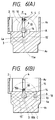
- Fig. 6(A) shows an initial stage of the fitting condition in which after the male housing B is opposed to the hood A2, the cam follower pin 10 is caused to pass past the provisionally- retaining projections 5 into the inlet of the upper cam groove 15 through the introduction groove 15a.
- the showing of the male housing B is omitted, and the cam follow pin 10 is shown.
- Fig. 6(B) shows the completely-fitted condition in which after the cam member C is angularly moved about 90 degrees from the initially-fitted position, the female and male housings A and B are completely fitted together, and the rotation retaining plate 14 on the rotation shaft 13 reaches the inner end 4a of the pin guide groove.
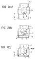
- Figs. 7(A) to 7(C) are plan views showing the process of the fitting of the female and male housings A and B.
- Fig. 7(A) shows the initial fitting condition
- Fig. 7(B) shows the intermediate fitting condition in which the cam member C is turned 45 degrees in the direction of arrow P
- Fig. 7(C) shows the completely-fitted condition in which a projection 9a of the lock arm 9 of the male housing B is engaged with the retaining portion 2 of the female housing A to thereby lock the two housings relative to each other.
- the upwardly-flexed flexible lock member 18 reaches the complete lock hole 20 (see Fig. 1) to be returned, so that the cam member C is locked against angular movement.
- the two housings are moved in their fitting directions by the angular movement of the cam member C, and at this time the fitting is achieved with a small force thanks to the engagement of the cam follower pins 10 and 3 in the cam grooves 15 and 15', and therefore the operation can be carried out quite smoothly.
- the thumbpiece 16 of the cam member C is inclined relative to the edges of the female and male housings A and B, and the flexible lock member 18 is projected from the opening 17 beyond the upper surface of the rotation plate 12, and therefore an incomplete fitting can be prevented.
- Figs. 8 to 11 show the second embodiment of the invention.
- a thumbpiece 16' of a cam member C1 is withdrawably mounted on a rotation plate 12, and the thumbpiece 16' can be locked when female and male housings A and B are completely fitted together.
- the thumbpiece 16' has a head 22 formed on a body 21, and has legs 23 formed respectively on opposite sides of a lower surface thereof, and a complete lock piece 24 is projected from each leg 23.
- Provisional lock pawls 25 are formed respectively on the opposite end surfaces of the body 21, and a complete lock pawl 26 is formed on each lock piece 24.
- a thumbpiece holder 27 is formed on an outer surface of the rotation plate 12 at a central portion thereof, and is disposed parallel to a line interconnecting introduction grooves 15a and 15a (see Fig. 1) of cam grooves 15 and 15' provided respectively on the opposite sides of the thumbpiece holder.
- a pair of holes 28 for respectively passing the legs 23 therethrough are formed through the rotation plate, and a rotation shaft 13 is disposed centrally of the distance between the two holes 28.
- the rotation shaft 13 of the cam member C1 is inserted into a pin guide groove 4 to achieve a provisionally-retained condition.
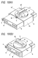
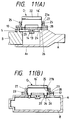
- the thumbpiece 16' is inserted into the holder 27, one of the pair of lock pieces 24 is abutted against an outer surface of a hood A2 of the female housing A, and at the same time the provisional lock pawls 25 and 25 are engaged respectively with retaining portions 27a of the holder 27, so that the thumbpiece is provisionally locked, as shown in Figs. 10(A) and 11(A).
- the cam member C1 can easily be angularly moved in a direction of arrow P by grasping the head 22 of the thumbpiece 16'.
- Fig. 10(A) shows a condition in which the male housing B begins to be fitted in the hood A2 in the provisionally-locked condition of the cam member C1 and the thumbpiece 16'.
- Fig. 11(A) shows a condition in which a cam follower pin 10 of the male housing 10 passes past provisionally-retaining pins 5, and reaches the inlet of the cam groove 15.
- Figs. 10(B) and 11(B) show a completely-fitted condition of the female and male housings A and B achieved by the angular movement of the cam member C1.
- the two legs 23 are passed respectively through the holes 28 of the rotation plate 12, and the lock pieces 24 are inserted respectively into the complete lock holes 20' of the female housing A, and the complete lock pawls 26 are engaged respectively with the edges of these holes, and the provisional lock pawls 25 are engaged respectively with retaining portions 27b in the holder 27, so that the thumbpiece is locked.
- the thumbpiece 16' is locked only when the female and male housings A and B are completely fitted together.
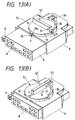
- Figs. 12 and 13 show a modification of the second embodiment.
- an elongate projection 30 of a T-shaped cross-section is formed on a lower end of a thumbpiece 16'' of a cam member C2, and is slidably inserted in an insertion groove 32 formed in an outer surface of a rotation plate 12.
- One end of the insertion groove 32 is open to the outer peripheral edge of the rotation plate 12, and the other end thereof is closed.
- the thumbpiece 16'' as well as the insertion groove 32 is slightly smaller than the diameter of the rotation plate 12, and is disposed perpendicular to a line interconnecting introduction grooves 15a and 15a disposed respectively on opposite sides thereof.
- a complete lock projection 31 is formed on the side surface of the thumbpiece 16'' at one end portion thereof.
- a lock wall 33 for the thumbpiece 16'', as well as a half-fitting prevention guide wall 35 are formed on a hood A2 of a female housing A, and is disposed rearwardly of a pin guide groove 4 and a cam follower pin 3.
- the lock wall 33 has a U-shape, and can fit on one end of the thumbpiece 16'', and a recess 34 for engagement with the projection 31 is formed in an inner surface of the lock wall.
- Fig. 13(B) shows the condition in which the female and male housings A and B are completely fitted together, and the thumbpiece 16'' is completely locked. Namely, the thumbpiece 16'' is slidingly moved in a direction of arrow Q, so that one end thereof is engaged in the lock wall 33, and the projection 31 is engaged in the recess 34 to lock the thumbpiece. It is clear that the thumbpiece 16'' is not locked at the stage between the start and the end of the fitting operation.
- the cam member (the rotation plate or the angular movement-effecting thumbpiece) can not be locked, and therefore there can be provided the low insertion/withdrawal-force connector which prevents an incomplete fitting, thus ensuring the complete fitting, and is highly reliable in electrical connection.
- the pair of housings are moved toward each other in the fitting direction, and therefore the fitting operation and the disengagement operation can be easily effected, and this construction is suited for a multi-pole connector, and the number of operation steps is reduced because the cam member does not need to be removed.
Landscapes
- Details Of Connecting Devices For Male And Female Coupling (AREA)
Applications Claiming Priority (2)
| Application Number | Priority Date | Filing Date | Title |
|---|---|---|---|
| JP16468/91U | 1991-02-28 | ||
| JP1991016468U JP2532620Y2 (ja) | 1991-02-28 | 1991-02-28 | 低挿抜力コネクタ |
Publications (3)
| Publication Number | Publication Date |
|---|---|
| EP0501502A2 true EP0501502A2 (de) | 1992-09-02 |
| EP0501502A3 EP0501502A3 (en) | 1993-03-17 |
| EP0501502B1 EP0501502B1 (de) | 1996-07-31 |
Family
ID=11917094
Family Applications (1)
| Application Number | Title | Priority Date | Filing Date |
|---|---|---|---|
| EP92103441A Expired - Lifetime EP0501502B1 (de) | 1991-02-28 | 1992-02-28 | Verbinder mit niedriger Einsteck-/Rückziehkraft |
Country Status (4)
| Country | Link |
|---|---|
| US (1) | US5205752A (de) |
| EP (1) | EP0501502B1 (de) |
| JP (1) | JP2532620Y2 (de) |
| DE (1) | DE69212511T2 (de) |
Cited By (13)
| Publication number | Priority date | Publication date | Assignee | Title |
|---|---|---|---|---|
| EP0622720A1 (de) * | 1993-04-27 | 1994-11-02 | International Business Machines Corporation | Auswurfanordnung für Computer |
| DE4443349A1 (de) * | 1994-12-06 | 1996-06-13 | Delphi Automotive Systems Gmbh | Elektrische Steckverbindung |
| WO1997007567A1 (de) * | 1995-08-17 | 1997-02-27 | The Whitaker Corporation | Steckeranordnung mit einem betätigungsschieber |
| EP0731536A3 (de) * | 1995-03-08 | 1997-08-06 | Framatome Connectors Int | Verbindungsanordnung mit doppeltem Exzenter |
| EP0801442A1 (de) * | 1996-04-09 | 1997-10-15 | Harness System Technologies Research, Ltd. | Verbindungsvorrichtung für elektrische Steckverbinder |
| EP0843387A3 (de) * | 1996-11-13 | 1999-04-07 | Harness System Technologies Research, Ltd. | Stecker Verbindungsstruktur |
| EP0898335A3 (de) * | 1997-07-18 | 1999-10-13 | Molex Incorporated | Elektrische Verbinderanordnung versehen mit Mitteln zur gleichzeitigen Verbindung von Stecker und Buchse |
| EP0793304A3 (de) * | 1996-02-27 | 1999-12-15 | Harness System Technologies Research, Ltd. | Verbindungsanordnung im Stecker |
| EP0889555A3 (de) * | 1997-07-01 | 2000-05-17 | Sumitomo Wiring Systems, Ltd. | Elektrischer Verbinder Zusammenbau |
| EP1130691A3 (de) * | 2000-03-03 | 2002-11-27 | Sumitomo Wiring Systems, Ltd. | Hebelsteckverbinder |
| EP1653567A1 (de) * | 2004-10-29 | 2006-05-03 | ATMEL Germany GmbH | Steckverbindungsmodule einer Steckverbindung zum gleichzeitigen Verbinden einer Vielzahl elektrischer Kontakte |
| EP2426792A1 (de) * | 2010-09-07 | 2012-03-07 | ITT Manufacturing Enterprises, Inc. | Steckverbindungsvorrichtung |
| US8435065B2 (en) | 2010-09-07 | 2013-05-07 | Itt Manufacturing Enterprises, Inc. | Plug-in unit |
Families Citing this family (16)
| Publication number | Priority date | Publication date | Assignee | Title |
|---|---|---|---|---|
| JP2567893Y2 (ja) | 1991-07-29 | 1998-04-08 | 住友電装株式会社 | コネクタ |
| DE69401824T2 (de) * | 1993-01-06 | 1997-06-12 | Sumitomo Wiring Systems | Steckverbinder, der die Betätigung eines Hebels benutzt |
| DE69426631T2 (de) * | 1993-11-05 | 2001-05-23 | Sumitomo Wiring Systems, Ltd. | Hebelsteckverbinder |
| JP3035489B2 (ja) * | 1995-08-25 | 2000-04-24 | 三菱電機株式会社 | 部品装着機構及び装置装着機構及び部品装着方法 |
| JP3570662B2 (ja) * | 1997-04-14 | 2004-09-29 | 矢崎総業株式会社 | 低挿入力コネクタ |
| US6544053B2 (en) * | 2000-09-18 | 2003-04-08 | Tyco Electronics Amp Gmbh | Plug connector arrangement |
| US6638085B1 (en) * | 2002-05-09 | 2003-10-28 | Tyco Electronics Corp. | Electrical connector with dual rack mate assist |
| US6767231B1 (en) * | 2003-09-25 | 2004-07-27 | Tyco Electronics Corporation | Electrical connector with flexible blocking feature |
| US7684179B1 (en) | 2005-12-08 | 2010-03-23 | Juniper Networks, Inc. | Actuation mechanism for vertical insertion, retention and extraction of an electronic component |
| CN101937258A (zh) * | 2009-06-30 | 2011-01-05 | 鸿富锦精密工业(深圳)有限公司 | 电子装置 |
| US8405966B2 (en) * | 2010-11-23 | 2013-03-26 | Dell Products L.P. | Memory carrier and IHS coupling system |
| JP5830408B2 (ja) * | 2012-02-20 | 2015-12-09 | 矢崎総業株式会社 | レバー式コネクタ |
| DE102018131378A1 (de) * | 2018-12-07 | 2020-01-09 | Lisa Dräxlmaier GmbH | Kontaktierungssystem zum herstellen einer elektrischen steckverbindung |
| US11751643B2 (en) * | 2019-02-17 | 2023-09-12 | Herman Jimenez | Connection device |
| CN210224457U (zh) * | 2019-09-11 | 2020-03-31 | 昆山纬绩资通有限公司 | 模块连接器 |
| US11910556B1 (en) * | 2022-08-10 | 2024-02-20 | Quanta Computer Inc. | Fastener with gear usage for tray install and eject |
Family Cites Families (8)
| Publication number | Priority date | Publication date | Assignee | Title |
|---|---|---|---|---|
| GB952652A (en) * | 1961-09-08 | 1964-03-18 | Belling & Lee Ltd | Improvements in two-part connectors |
| DE3527916A1 (de) * | 1985-08-03 | 1987-02-12 | Cannon Electric Gmbh | Elektrische steckerkupplung |
| JPS6488475A (en) * | 1987-09-29 | 1989-04-03 | Fuji Xerox Co Ltd | Image forming device |
| JPH0679182B2 (ja) * | 1987-09-29 | 1994-10-05 | シャープ株式会社 | 帯電装置の高圧電源接続構造 |
| JPH01151181A (ja) * | 1987-12-09 | 1989-06-13 | Yazaki Corp | 低挿抜力多極コネクタ |
| DE3826332C1 (en) * | 1988-08-03 | 1989-08-24 | Leopold Kostal Gmbh & Co Kg, 5880 Luedenscheid, De | Electrical plug connector coupling |
| EP0388488B1 (de) * | 1989-03-21 | 1993-01-13 | CANNON ELECTRIC GmbH | Verriegelbarer elektrischer Steckverbinder |
| JPH088538Y2 (ja) * | 1990-01-23 | 1996-03-06 | シャープ株式会社 | Icカードのイジェクト装置 |
-
1991
- 1991-02-28 JP JP1991016468U patent/JP2532620Y2/ja not_active Expired - Fee Related
-
1992
- 1992-02-26 US US07/841,794 patent/US5205752A/en not_active Expired - Lifetime
- 1992-02-28 DE DE69212511T patent/DE69212511T2/de not_active Expired - Fee Related
- 1992-02-28 EP EP92103441A patent/EP0501502B1/de not_active Expired - Lifetime
Cited By (20)
| Publication number | Priority date | Publication date | Assignee | Title |
|---|---|---|---|---|
| EP0622720A1 (de) * | 1993-04-27 | 1994-11-02 | International Business Machines Corporation | Auswurfanordnung für Computer |
| DE4443349A1 (de) * | 1994-12-06 | 1996-06-13 | Delphi Automotive Systems Gmbh | Elektrische Steckverbindung |
| WO1996018202A1 (de) * | 1994-12-06 | 1996-06-13 | Delphi Automotive Systems Deutschland Gmhb | Elektrische steckverbindung |
| US5839912A (en) * | 1994-12-06 | 1998-11-24 | Delphi Automotive Systems Deutschland Gmbh | Electrical plug-and-socket connection |
| EP0731536A3 (de) * | 1995-03-08 | 1997-08-06 | Framatome Connectors Int | Verbindungsanordnung mit doppeltem Exzenter |
| WO1997007567A1 (de) * | 1995-08-17 | 1997-02-27 | The Whitaker Corporation | Steckeranordnung mit einem betätigungsschieber |
| EP0793304A3 (de) * | 1996-02-27 | 1999-12-15 | Harness System Technologies Research, Ltd. | Verbindungsanordnung im Stecker |
| EP0801442A1 (de) * | 1996-04-09 | 1997-10-15 | Harness System Technologies Research, Ltd. | Verbindungsvorrichtung für elektrische Steckverbinder |
| US5921791A (en) * | 1996-04-09 | 1999-07-13 | Harness System Technologies Research, Ltd. | Connector connecting structure |
| US6036510A (en) * | 1996-04-09 | 2000-03-14 | Harness System Technologies Research, Ltd. | Connector connecting structure |
| EP0843387A3 (de) * | 1996-11-13 | 1999-04-07 | Harness System Technologies Research, Ltd. | Stecker Verbindungsstruktur |
| US6126470A (en) * | 1996-11-13 | 2000-10-03 | Harness System Technologies Research, Ltd. | Connector connecting structure |
| EP0889555A3 (de) * | 1997-07-01 | 2000-05-17 | Sumitomo Wiring Systems, Ltd. | Elektrischer Verbinder Zusammenbau |
| EP0898335A3 (de) * | 1997-07-18 | 1999-10-13 | Molex Incorporated | Elektrische Verbinderanordnung versehen mit Mitteln zur gleichzeitigen Verbindung von Stecker und Buchse |
| EP1130691A3 (de) * | 2000-03-03 | 2002-11-27 | Sumitomo Wiring Systems, Ltd. | Hebelsteckverbinder |
| EP1653567A1 (de) * | 2004-10-29 | 2006-05-03 | ATMEL Germany GmbH | Steckverbindungsmodule einer Steckverbindung zum gleichzeitigen Verbinden einer Vielzahl elektrischer Kontakte |
| DE102004053516A1 (de) * | 2004-10-29 | 2006-05-11 | Atmel Germany Gmbh | Steckverbindungsmodule einer Steckverbindung zum gleichzeitigen Verbinden einer Vielzahl elektrischer Kontakte |
| US7322837B2 (en) | 2004-10-29 | 2008-01-29 | Atmel Germany Gmbh | Plug connector modules of a plug connector for simultaneously connecting a plurality of electrical contacts |
| EP2426792A1 (de) * | 2010-09-07 | 2012-03-07 | ITT Manufacturing Enterprises, Inc. | Steckverbindungsvorrichtung |
| US8435065B2 (en) | 2010-09-07 | 2013-05-07 | Itt Manufacturing Enterprises, Inc. | Plug-in unit |
Also Published As
| Publication number | Publication date |
|---|---|
| EP0501502A3 (en) | 1993-03-17 |
| EP0501502B1 (de) | 1996-07-31 |
| DE69212511T2 (de) | 1996-12-05 |
| JP2532620Y2 (ja) | 1997-04-16 |
| US5205752A (en) | 1993-04-27 |
| JPH04106876U (ja) | 1992-09-16 |
| DE69212511D1 (de) | 1996-09-05 |
Similar Documents
| Publication | Publication Date | Title |
|---|---|---|
| EP0501502B1 (de) | Verbinder mit niedriger Einsteck-/Rückziehkraft | |
| EP0727847B1 (de) | Handhebel betätigter Verbinder | |
| US5401179A (en) | Locking mechanism for a connector assembly of low engaging/disengaging force type | |
| US5709560A (en) | Connector having a pivotable connection-assistance member | |
| US5104330A (en) | Electric connector | |
| US5344194A (en) | Connectors with lever | |
| US5171156A (en) | Low-operating-force connector | |
| US6312277B1 (en) | Connector position assurance device for a connector | |
| US7470138B1 (en) | Connector position assurance device and connector assembly apparatus incorporating the same | |
| EP0624922B1 (de) | Elektrischer Steckverbinder | |
| US6655971B2 (en) | Lever-type connector with a peak operation resistance shortly before complete connection | |
| US7255581B2 (en) | Lever-type connector | |
| US6102726A (en) | Connector fitting structure | |
| US5919056A (en) | Connector disengaging mechanism | |
| US7011536B2 (en) | Connector and a connector assembly | |
| JP2738258B2 (ja) | レバー式コネクタ | |
| US6863551B2 (en) | Connector, set of connectors and method of connecting a connector | |
| EP0954061B1 (de) | Ein Verbinder | |
| JP3514284B2 (ja) | コネクタ固定方法及びそれに用いるコネクタ | |
| US5647752A (en) | Lever-type connector | |
| JP3249739B2 (ja) | 半嵌合防止コネクタ | |
| US6309242B1 (en) | Electrical connector with a coupling state indicating mechanism | |
| JP2912471B2 (ja) | ツーピースコネクタ | |
| JPH09139252A (ja) | コネクタ嵌合機構 | |
| JP2538723B2 (ja) | レバ―付コネクタ |
Legal Events
| Date | Code | Title | Description |
|---|---|---|---|
| PUAI | Public reference made under article 153(3) epc to a published international application that has entered the european phase |
Free format text: ORIGINAL CODE: 0009012 |
|
| AK | Designated contracting states |
Kind code of ref document: A2 Designated state(s): DE FR GB IT |
|
| PUAL | Search report despatched |
Free format text: ORIGINAL CODE: 0009013 |
|
| AK | Designated contracting states |
Kind code of ref document: A3 Designated state(s): DE FR GB IT |
|
| 17P | Request for examination filed |
Effective date: 19930630 |
|
| 17Q | First examination report despatched |
Effective date: 19941214 |
|
| GRAH | Despatch of communication of intention to grant a patent |
Free format text: ORIGINAL CODE: EPIDOS IGRA |
|
| GRAH | Despatch of communication of intention to grant a patent |
Free format text: ORIGINAL CODE: EPIDOS IGRA |
|
| GRAA | (expected) grant |
Free format text: ORIGINAL CODE: 0009210 |
|
| AK | Designated contracting states |
Kind code of ref document: B1 Designated state(s): DE FR GB IT |
|
| REF | Corresponds to: |
Ref document number: 69212511 Country of ref document: DE Date of ref document: 19960905 |
|
| ET | Fr: translation filed | ||
| ITF | It: translation for a ep patent filed | ||
| PLBE | No opposition filed within time limit |
Free format text: ORIGINAL CODE: 0009261 |
|
| STAA | Information on the status of an ep patent application or granted ep patent |
Free format text: STATUS: NO OPPOSITION FILED WITHIN TIME LIMIT |
|
| 26N | No opposition filed | ||
| REG | Reference to a national code |
Ref country code: GB Ref legal event code: IF02 |
|
| PGFP | Annual fee paid to national office [announced via postgrant information from national office to epo] |
Ref country code: FR Payment date: 20050208 Year of fee payment: 14 |
|
| PGFP | Annual fee paid to national office [announced via postgrant information from national office to epo] |
Ref country code: GB Payment date: 20050223 Year of fee payment: 14 |
|
| PGFP | Annual fee paid to national office [announced via postgrant information from national office to epo] |
Ref country code: DE Payment date: 20050224 Year of fee payment: 14 |
|
| PG25 | Lapsed in a contracting state [announced via postgrant information from national office to epo] |
Ref country code: GB Free format text: LAPSE BECAUSE OF NON-PAYMENT OF DUE FEES Effective date: 20060228 |
|
| PGFP | Annual fee paid to national office [announced via postgrant information from national office to epo] |
Ref country code: IT Payment date: 20060228 Year of fee payment: 15 |
|
| PG25 | Lapsed in a contracting state [announced via postgrant information from national office to epo] |
Ref country code: DE Free format text: LAPSE BECAUSE OF NON-PAYMENT OF DUE FEES Effective date: 20060901 |
|
| GBPC | Gb: european patent ceased through non-payment of renewal fee |
Effective date: 20060228 |
|
| REG | Reference to a national code |
Ref country code: FR Ref legal event code: ST Effective date: 20061031 |
|
| PG25 | Lapsed in a contracting state [announced via postgrant information from national office to epo] |
Ref country code: FR Free format text: LAPSE BECAUSE OF NON-PAYMENT OF DUE FEES Effective date: 20060228 |
|
| PG25 | Lapsed in a contracting state [announced via postgrant information from national office to epo] |
Ref country code: IT Free format text: LAPSE BECAUSE OF NON-PAYMENT OF DUE FEES Effective date: 20070228 |