EP0501599A1 - Vorrichtung zur Absorption von Kohlendioxyd aus Gasen - Google Patents
Vorrichtung zur Absorption von Kohlendioxyd aus Gasen Download PDFInfo
- Publication number
- EP0501599A1 EP0501599A1 EP92250041A EP92250041A EP0501599A1 EP 0501599 A1 EP0501599 A1 EP 0501599A1 EP 92250041 A EP92250041 A EP 92250041A EP 92250041 A EP92250041 A EP 92250041A EP 0501599 A1 EP0501599 A1 EP 0501599A1
- Authority
- EP
- European Patent Office
- Prior art keywords
- gas
- fillers
- liquid
- absorbing
- carbon dioxide
- Prior art date
- Legal status (The legal status is an assumption and is not a legal conclusion. Google has not performed a legal analysis and makes no representation as to the accuracy of the status listed.)
- Ceased
Links
Images



Classifications
-
- B—PERFORMING OPERATIONS; TRANSPORTING
- B01—PHYSICAL OR CHEMICAL PROCESSES OR APPARATUS IN GENERAL
- B01D—SEPARATION
- B01D47/00—Separating dispersed particles from gases, air or vapours by liquid as separating agent
-
- B—PERFORMING OPERATIONS; TRANSPORTING
- B01—PHYSICAL OR CHEMICAL PROCESSES OR APPARATUS IN GENERAL
- B01J—CHEMICAL OR PHYSICAL PROCESSES, e.g. CATALYSIS OR COLLOID CHEMISTRY; THEIR RELEVANT APPARATUS
- B01J19/00—Chemical, physical or physico-chemical processes in general; Their relevant apparatus
- B01J19/32—Packing elements in the form of grids or built-up elements for forming a unit or module inside the apparatus for mass or heat transfer
-
- B—PERFORMING OPERATIONS; TRANSPORTING
- B01—PHYSICAL OR CHEMICAL PROCESSES OR APPARATUS IN GENERAL
- B01D—SEPARATION
- B01D53/00—Separation of gases or vapours; Recovering vapours of volatile solvents from gases; Chemical or biological purification of waste gases, e.g. engine exhaust gases, smoke, fumes, flue gases, aerosols
- B01D53/14—Separation of gases or vapours; Recovering vapours of volatile solvents from gases; Chemical or biological purification of waste gases, e.g. engine exhaust gases, smoke, fumes, flue gases, aerosols by absorption
- B01D53/18—Absorbing units; Liquid distributors therefor
- B01D53/185—Liquid distributors
-
- B—PERFORMING OPERATIONS; TRANSPORTING
- B01—PHYSICAL OR CHEMICAL PROCESSES OR APPARATUS IN GENERAL
- B01J—CHEMICAL OR PHYSICAL PROCESSES, e.g. CATALYSIS OR COLLOID CHEMISTRY; THEIR RELEVANT APPARATUS
- B01J2219/00—Chemical, physical or physico-chemical processes in general; Their relevant apparatus
- B01J2219/32—Details relating to packing elements in the form of grids or built-up elements for forming a unit of module inside the apparatus for mass or heat transfer
- B01J2219/322—Basic shape of the elements
- B01J2219/32203—Sheets
- B01J2219/32265—Sheets characterised by the orientation of blocks of sheets
- B01J2219/32272—Sheets characterised by the orientation of blocks of sheets relating to blocks in superimposed layers
Definitions
- the present invention relates to an apparatus for absorbing carbon dioxide gas which removes carbon dioxide gas from a combustion exhaust gas.
- CO2 is recovered from the exhaust gas, and the recovered CO2 is used as a raw material of a carbon dioxide gas-containing drink.
- the recovered CO2 is used as a raw material for a so-called EOR (Enhanced Oil Recovery) plant in which CO2 is introduced into an oil layer under pressure which has finished the secondary recovery, and the remaining crude oil is recovered (article entitled: Process to recover CO2 from flue gas gets first large-scale tryout in Texas, Oil & Journal, Feb. 14, 1983).
- EOR Enhanced Oil Recovery
- CO2 recovery methods there can be employed a method comprising the step of chemically absorbing CO2 by an aqueous alkaline solution such as a solution of an amine compound or potassium carbonate, and a method comprising the step of physically absorbing CO2 by a solvent such as methanol, polyethylene glycol methylether or propylene carbonate, but a typical method is absorption using an aqueous solution of an amine compound such as monoethanolamine, diethanolamine or triethanolamine as an absorbent.
- an aqueous alkaline solution such as a solution of an amine compound or potassium carbonate
- a solvent such as methanol, polyethylene glycol methylether or propylene carbonate
- the absorption reaction of the CO2 gas proceeds in accordance with the following formula (1): OHCH2CH2NH2 + H2O + CO2 - OHCH2CH2NH3HCO3
- An amine such as monoethanolamine is easily soluble in water, and forms a uniform aqueous solution can be prepared at any concentration, but in general, the aqueous amine solution is used at a concentration of about 20 to about 30%.
- monoethanolamine and CO2 react with each other under equimolar conditions. In view of this fact, the absorption capacity of CO2 by monoethanolamine is very large, and although it depends upon temperature, a CO2/monoethanolamine (molar ratio) of 0.50 at about 50°C can be attained.
- the CO2-absorbing apparatus in which the above-mentioned absorbing liquid is used, such an apparatus is packed with fillers capable of obtaining the largest possible contact area between an aqueous monoethanolamine solution and CO2, and the absorbent is fed from the top and a gas containing CO2 is fed from the bottom.
- the absorbing liquid is brought into contact with the CO2 gas to absorb CO2, while the absorbing liquid streams down through the fillers.
- ceramic products such as so-called Raschig rings, Lessing rings or Berl Saddles are usually used.
- the feature of the fillers is that the gas contact area of the fillers per unit volume is large, and therefore it is preferred that the fillers have a smaller size.
- the fillers which is often used have a cylindrical shape, a diameter of 10-15 mm and a height of 10-15 mm, but the drawback of such fillers is that a pressure loss is large, so that the layer of the fillers cannot have a sufficient thickness.
- a pressure loss of more than 100 mmH2O per 10 m of the filler layer takes place at a gas flow velocity of about 0.15 m/sec.
- the pressure loss which is practically allowable is preferably a small value of about 100 to about 200 mm.
- the apparatus In order to reduce such pressure loss, it is also possible to enlarge the size of the fillers. For example, when Raschig rings having a diameter of 50 mm and a height of 50 mm is used, the pressure loss decreases, but the gas contact area of the fillers per unit volume thereof also decreases to about one fifth (1/5). Therefore, the apparatus has a large volume in an inversely proportion manner to the decrease in the filler/volume ratio, and so it is impossible to avoid the drawback that the installation area for the apparatus becomes large.
- an object of the present invention is to provide an apparatus for absorbing carbon dioxide gas which can eliminate the drawbacks of a conventional gas-liquid contact apparatus in which fillers such as Raschig rings are used.
- the present invention relates to an apparatus for absorbing carbon dioxide gas which absorbs and removes the carbon dioxide gas from a combustion exhaust gas using a carbon dioxide gas-absorbing liquid, the apparatus being characterized in that the apparatus is packed with fillers which have a tubular structure with various cross-sectional shapes and whose tubular portion has a straight linear shape, and a plurality of the fillers are arranged so that the gas-liquid contact surfaces of the fillers are substantially parallel with the stream of the gas.
- the apparatus is packed with fillers which have a tubular structure with a certain sectional shape and a straight tubular portion, and the fillers are arranged so that the straight tubular portions of the fillers are parallel with the stream of the gas, the stream of the gas is parallel with the absorption surfaces, and the enlargement, reduction, collision and eddy formation of the gas stream can be prevented, so that troublesome pressure losses attributable to these scarcely occur.
- An absorbing solution is held on the absorbing surfaces of the tubular fillers and comes into contact with the gas stream to absorb CO2, while the absorbing solution flows down along the surfaces of the fillers. Due to this constitution, the pressure loss can be decreased to a very small value, in contrast to a case where conventional fillers such as Raschig rings are used.
- liquid spray nozzles comprising many branched pipes are disposed above the fillers which have a tubular structure, and the CO2 gas-absorbing solution is sprayed through these nozzles.
- these branched pipes must be arranged so as to entirely cover the upper openings of the tubular fillers.
- the branched pipes have to cover most of the passages for the combustion exhaust gas. Therefore, these branched pipes block the passage of the exhaust gas and become another cause of pressure losses. This is a new problem to be solved.
- Another object of the present invention is to provide a gas-liquid contact apparatus in which the structure of the above-mentioned solution spray nozzles is improved, i.e., a gas-liquid contact apparatus equipped with a solution spray head capable of further decreasing the pressure loss.
- the present invention is directed to an apparatus for absorbing carbon dioxide gas in which a solution spray head is arranged above the above-mentioned fillers; the under surface of the spray head is curved; many small holes are formed in the curved undersurface of the spray head; and the upper openings of the fillers are positioned in an angular range defined by the normals of the curved undersurface of the spray head.
- the above-mentioned solution spray head of the absorbing apparatus can be applied to a gas-liquid contact apparatus which is packed with fillers and in which a liquid sprayed from a position above the fillers, allowed to stream down along the surfaces of the fillers, and brought into contact with a gas fed from the underside of the apparatus, which apparatus comprises a liquid spray means connected to a transport line of the liquid, and the fillers which have a tubular structure with a certain cross-sectional shape and a straight tubular portion and which are arranged so that gas-liquid contact surfaces become parallel with the stream of the gas.
- tubular fillers which can be employed in the present invention may assume various shapes, but, needless to say, they may have a single shape or a combination of plurality of shapes.
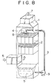
- reference numeral 1 indicates an apparatus for absorbing CO2 gas itself
- 2 indicates fillers which have a tubular structure with a straight tubular portion
- 3 denotes a transport line for a CO2 gas-absorbing liquid
- 4 denotes a liquid spray nozzle
- 5 is a tank for the absorbing liquid which has absorbed CO2
- 6 is an exhaust gas containing CO2
- 7 is a clean exhaust gas from which CO2 has been removed
- 8 indicates upper openings of the fillers 2
- 9 is a pump.
- tubular fillers 2 are shown in detail in Fig. 2, and De in the drawing means the diameter or width of each orifice.
- a filler material 2' is molded into a shape having an orifice width of 15 mm with an area of 300 mm2 and a height of 500 mm.
- the thus molded filler pieces are represented by 21 22, 23 and 24 in Fig. 1. These are superposed upon each other as much as 20 steps.
- the stream of the gas is in parallel with the absorbing surfaces of the fillers, and the enlargement, reduction, collision and eddy formation of the gas stream can be prevented during the passages of the gas, preventing useless pressure losses attributable thereto.
- the absorbing liquid is held on the absorbing surfaces of the tubular fillers and is brought into contact with the gas stream to absorb CO2, while the absorbing liquid streams down along the surfaces of the fillers. Only pressure losses due to friction occur, but such losses are minimal and not wasteful, and rather necessary for the absorption of CO2.
- Line A in Fig. 3 indicates the result of gas absorption by the use of the apparatus shown in Fig. 1, which is packed with the tubular fillers shown in Fig. 2.
- the abscissa axis and the ordinate axis of Fig. 3 denote a gas linear velocity (m/sec) and the pressure loss of the absorbing layer (mmH2O), respectively.
- Fig. 3 also shows, with line B, a relation between the pressure loss and the gas linear velocity as a comparative example in which Raschig ring fillers each having a diameter of 15 mm and a height of 15 mm are used.
- the pressure loss is smaller than in the case that the Raschig ring filler layer is used. Furthermore, when the total pressure loss of the absorbing layer is 100 mmH2O, a gas flow velocity in the embodiment of present invention is 3 m/sec., but that of the case where the Raschig ring fillers are used is only 0.15 m/sec. Therefore, the area of an absorbing tower may be 1/20 of that in the case where the Raschig ring fillers are used, and the embodiment of the present invention is very advantageous from an economical viewpoint.
- Table 1 shows CO2 absorption ratios in the embodiment of the present invention in which an aqueous solution of 30% by weight of monoethanolamine is fed at a solution/gas ratio of 3 to 1 (in units of 1/Nm3).
- the CO2 absorption/removal ratio increases along with the gas linear velocity but becomes substantially constant beyond a certain gas linear velocity. Accordingly, even when the gas flow velocity is further increased, the CO2 removal ratio scarcely improves, but the pressure loss increases more and more, which is not economical. Therefore, it is desirable to select a gas flow velocity of about 2 to about 3 m/sec. at which the absorption ratio almost reaches the constant level as the gas flow velocity increases.
- Table 1 Gas Linear Velocity (m/sec.) CO2 Removal Ratio (%) 1.0 91.1 2.0 93.8 3.0 94.2 4.0 94.4
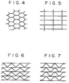
- the shape of the tubular structures is not limited to the lattice shape shown in Fig. 2, and shapes such as hexagon, rectangle, triangle, U-shape and the like shown in Figs. 4 to 7 are acceptable, so long as tubular structures with such a shape can form parallel gas streams.
- materials for the fillers there can be utilized ceramics, metals, ceramic fibers, such as silica fibers, as well as plastics, such as polyethylene, which do not corrode, swell or become damaged otherwise under the influence of the absorbing liquid.
- the preparation process for the fillers is usually extrusion molding if the shape shown in Fig. 2 is employed.
- a combination of a flat plate and a molded plate, or a corrugation machine molding process can also be utilized, and therefore an economical preparation process can be selected depending on the shape and the material.
- the orifice diameter De of this tubular structure is preferably from about 10 to about 20 mm.
- the orifice diameter De referred to in this specification is an equivalent diameter which is defined by: (sectional area of the stream) ⁇ (outer peripheral length of the sectional area of the stream) x 4.
- This outer peripheral length of the sectional area of the stream means the length of the periphery which comes in contact with the fluid, i.e., the outer peripheral length of a cross section of the stream in a direction vertical to the stream.
- This De is used in comparing the diameter of the orifice having a rectangular section or a triangular section with the diameter of the orifice having a square section.
- the wall thickness should be decided considering necessary strength of the structures and thickness necessary for the preparation of the filler, while trying to make the wall thinner.
- an apparatus for absorbing carbon dioxide gas which can save energy and can be made smaller particularly in absorbing and removing CO2 from large amounts of the combustion exhaust gas.
- the liquid spray nozzle 4 is provided with nozzle holes which are formed by perforating the undersides of many pipes branching from an absorbing liquid transport line.
- reference numeral 4 indicates a liquid spray head, and the other numerals represent the same members as in Fig. 1.
- a CO2-absorbing liquid is fed to a liquid spray head 4 through a CO2-absorbing liquid transport line 3 and then reaches a position in the vicinity of many small holes 11 which are formed in a curved surface 10 and at the tip of the head 4 shown in Fig. 9. Then, the CO2-absorbing liquid is sprayed through the small holes 11 of the liquid spray head 4 over upper openings 8 of tubular fillers 2 disposed under the liquid spray head 4 by a pressure difference between the pressure of the fed CO2-absorbing liquid and the gas pressure of the combustion exhaust gas outside the liquid spray head 4.
- the internal pressure P of the CO2-absorbing liquid in the liquid spray head 4 acts on the inside wall surface of the head 4 from a vertical direction (a direction normal to the curved surface), as shown in Fig. 9.
- the small holes 11 are formed in the curved surface 10 of the liquid spray head 4, and therefore the pressure direction of the CO2-absorbing liquid follows the direction of the initial velocity of the liquid jetted through the small holes.
- the CO2-absorbing liquid is jetted at a mutually and substantially uniform velocity in directions L1 , L2 normal to the curved surface 10 having small holes (in Fig. 9, only two normal directions at opposite ends are shown). This principle is the same as in a funnel which is used to spray water on plants in a home garden.
- the CO2-absorbing liquid sprayed through the small holes 11 of the liquid spray head 4 does not produce a mist, but produces liquid droplets as in the case of the funnel. Consequently, the CO2 gas-absorbing liquid is scarcely entrained by the combustion exhaust gas which rises from the underside, whereby a loss of the CO2 gas-absorbing liquid can be prevented.
- liquid droplets can be easily formed by adjusting the pressure of the CO2-absorbing liquid which is fed to the liquid spray head 4.
- the above-mentioned constitution permits the CO2-absorbing liquid to be sprayed in the state of liquid droplets in the wide range with a single liquid spray head 4.
- the liquid spray head 4 can be constructed so as to have a very small sectional area compared to the sectional area of the gas stream passages, and therefore the pressure loss of the combustion exhaust gas attributed to the installation of the liquid spray head 4 is extremely small.
- the range over which the one liquid spray head 4 can spray is narrower as compared with the sectional area of the tubular fillers 2, two or more liquid spray heads 4 can be disposed, if necessary.
- the liquid spray heads 4 are arranged so that the upper openings 8 of the fillers may fall within the angle range defined by the normals of the curved surfaces having the small holes of the heads at extreme ends of all the liquid spray heads 4.
- the CO2-absorbing liquid sprayed through the small holes 11 comes into contact with the CO2-containing combustion exhaust gas 6, while the liquid streams down along the inside walls of the tubular fillers 2.
- the gas-liquid contact apparatus of the present invention has been described as the contact apparatus for the CO2-containing combustion exhaust gas and the CO2-absorbing liquid, but it should not be limited to the absorption of CO2 in the embodiments.
- the gas-liquid contact apparatus of the present invention can be widely used as an apparatus for bringing an ordinary gas into contact with a liquid.
- a liquid can be uniformly sprayed without noticeably clogging the passages of a gas, so that the gas-liquid contact can be achieved with little pressure losses.
- the liquid can be easily sprayed in the state of liquid droplets, and therefore the liquid is scarcely entrained by the gas and lost.
Landscapes
- Chemical & Material Sciences (AREA)
- Chemical Kinetics & Catalysis (AREA)
- Physics & Mathematics (AREA)
- Thermal Sciences (AREA)
- Organic Chemistry (AREA)
- Engineering & Computer Science (AREA)
- Analytical Chemistry (AREA)
- General Chemical & Material Sciences (AREA)
- Oil, Petroleum & Natural Gas (AREA)
- Treating Waste Gases (AREA)
- Gas Separation By Absorption (AREA)
Applications Claiming Priority (4)
| Application Number | Priority Date | Filing Date | Title |
|---|---|---|---|
| JP33089/91 | 1991-02-27 | ||
| JP3033089A JPH04271809A (ja) | 1991-02-27 | 1991-02-27 | 炭酸ガス吸収装置 |
| JP1991075290U JP2503201Y2 (ja) | 1991-09-19 | 1991-09-19 | 気液接触装置 |
| JP75290/91 | 1991-09-19 |
Publications (1)
| Publication Number | Publication Date |
|---|---|
| EP0501599A1 true EP0501599A1 (de) | 1992-09-02 |
Family
ID=26371733
Family Applications (1)
| Application Number | Title | Priority Date | Filing Date |
|---|---|---|---|
| EP92250041A Ceased EP0501599A1 (de) | 1991-02-27 | 1992-02-26 | Vorrichtung zur Absorption von Kohlendioxyd aus Gasen |
Country Status (2)
| Country | Link |
|---|---|
| EP (1) | EP0501599A1 (de) |
| KR (1) | KR950014023B1 (de) |
Cited By (5)
| Publication number | Priority date | Publication date | Assignee | Title |
|---|---|---|---|---|
| EP0606964A1 (de) * | 1993-01-13 | 1994-07-20 | The Kansai Electric Power Co., Inc. | Vorrichtung zur Durchführung eines Gas-Flüssigkeitkontaktes |
| RU2133140C1 (ru) * | 1998-03-05 | 1999-07-20 | Пензенская государственная архитектурно-строительная академия | Компактный тепломассообменный аппарат |
| EP1249273A1 (de) * | 2001-04-11 | 2002-10-16 | The Kansai Electric Power Co., Inc. | Gas-Flüssigkeit Kontaktplatte und Gas-Flüssigkeit Vorrichtung |
| WO2011009728A1 (de) * | 2009-07-22 | 2011-01-27 | Hitachi Power Europe Gmbh | Co2 -rauchgaswäscher mit mehreren gaswaschstufen |
| FR2983737A1 (fr) * | 2011-12-13 | 2013-06-14 | IFP Energies Nouvelles | Procede de desacidification d'un gaz avec mise en oeuvre d'un contacteur monolithe |
Families Citing this family (2)
| Publication number | Priority date | Publication date | Assignee | Title |
|---|---|---|---|---|
| KR100682452B1 (ko) * | 2005-08-03 | 2007-02-15 | (주)에이엠티퍼시픽 | 듀얼 플로우 트레이의 용량 증대를 위한 기액 접촉장치 |
| KR101943914B1 (ko) * | 2018-07-05 | 2019-01-30 | (주)청류에프앤에스 | 습식정화 필터링장치 및 이를 포함하는 배기가스 정화시스템 |
Citations (3)
| Publication number | Priority date | Publication date | Assignee | Title |
|---|---|---|---|---|
| GB977199A (en) * | 1960-06-28 | 1964-12-02 | American Radiator & Standard | Improvements in or relating to apparatus for providing intimate contact between two fluids |
| US3256001A (en) * | 1963-05-09 | 1966-06-14 | American Radiator & Standard | Gas scrubber |
| US4440731A (en) * | 1981-09-08 | 1984-04-03 | The Dow Chemical Company | Process for removal of carbon dioxide from industrial gases |
-
1992
- 1992-02-26 EP EP92250041A patent/EP0501599A1/de not_active Ceased
- 1992-02-27 KR KR1019920003103A patent/KR950014023B1/ko not_active Expired - Fee Related
Patent Citations (3)
| Publication number | Priority date | Publication date | Assignee | Title |
|---|---|---|---|---|
| GB977199A (en) * | 1960-06-28 | 1964-12-02 | American Radiator & Standard | Improvements in or relating to apparatus for providing intimate contact between two fluids |
| US3256001A (en) * | 1963-05-09 | 1966-06-14 | American Radiator & Standard | Gas scrubber |
| US4440731A (en) * | 1981-09-08 | 1984-04-03 | The Dow Chemical Company | Process for removal of carbon dioxide from industrial gases |
Cited By (6)
| Publication number | Priority date | Publication date | Assignee | Title |
|---|---|---|---|---|
| EP0606964A1 (de) * | 1993-01-13 | 1994-07-20 | The Kansai Electric Power Co., Inc. | Vorrichtung zur Durchführung eines Gas-Flüssigkeitkontaktes |
| EP0803277A3 (de) * | 1993-01-13 | 1997-12-29 | The Kansai Electric Power Co., Inc. | Vorrichtung zur Durchführung eines Gas-Flüssigkeitskontaktes |
| RU2133140C1 (ru) * | 1998-03-05 | 1999-07-20 | Пензенская государственная архитектурно-строительная академия | Компактный тепломассообменный аппарат |
| EP1249273A1 (de) * | 2001-04-11 | 2002-10-16 | The Kansai Electric Power Co., Inc. | Gas-Flüssigkeit Kontaktplatte und Gas-Flüssigkeit Vorrichtung |
| WO2011009728A1 (de) * | 2009-07-22 | 2011-01-27 | Hitachi Power Europe Gmbh | Co2 -rauchgaswäscher mit mehreren gaswaschstufen |
| FR2983737A1 (fr) * | 2011-12-13 | 2013-06-14 | IFP Energies Nouvelles | Procede de desacidification d'un gaz avec mise en oeuvre d'un contacteur monolithe |
Also Published As
| Publication number | Publication date |
|---|---|
| KR950014023B1 (ko) | 1995-11-20 |
| KR920016127A (ko) | 1992-09-24 |
Similar Documents
| Publication | Publication Date | Title |
|---|---|---|
| CN103338841B (zh) | 清洁过程气体的湿式洗涤器和方法 | |
| KR102377446B1 (ko) | 배기가스 중의 황 산화물의 양을 감소시키는 시스템 및 방법 | |
| CN100443399C (zh) | 湿法洗涤设备和用来控制NOx排放的方法 | |
| CN100371054C (zh) | 具有阶梯托盘的烟道气脱硫系统 | |
| KR101698999B1 (ko) | 선박 연도 가스 세척 장치 및 방법 | |
| US20190099706A1 (en) | Integrated system for seawater scrubbing of marine exhaust gas | |
| CA1107942A (en) | Gas sparging method | |
| CN201088903Y (zh) | 湿法烟气脱硫塔 | |
| KR101473285B1 (ko) | 습식 배연 탈류 장치 | |
| CN105854554A (zh) | 臭氧低温氧化脱硝工艺及系统 | |
| CN103623661B (zh) | 一种烟气净化塔 | |
| US4600567A (en) | Sulfur oxides scrubbing process | |
| KR950014023B1 (ko) | 기액접촉장치 | |
| KR20220040216A (ko) | 이산화탄소 흡수탑 및 이를 포함하는 배기 오염물질 저감장치 | |
| US20220134272A1 (en) | Compact venturi scrubber and method to treat gas streams utilizing the compact venturi scrubber | |
| KR102276560B1 (ko) | 질소산화물 및 황산화물 제거용 배기가스 처리 설비 | |
| CN201880465U (zh) | 海水脱硫喷淋塔 | |
| US20090151563A1 (en) | Extraction device | |
| FI86965C (fi) | Foerfarande och anordning foer rening av roekgaser | |
| KR100733075B1 (ko) | 가스층 다공판 장착 습식 배연 탈황장치 | |
| CN210171192U (zh) | 一种二氧化碳吸收塔 | |
| JPH04271809A (ja) | 炭酸ガス吸収装置 | |
| KR100542953B1 (ko) | 배가스 유입구 부분을 개선한 기-액 흡수탑 | |
| CN218307151U (zh) | 一种危废焚烧烟气处理设备 | |
| JPH10225615A (ja) | 湿式排煙脱硫装置 |
Legal Events
| Date | Code | Title | Description |
|---|---|---|---|
| PUAI | Public reference made under article 153(3) epc to a published international application that has entered the european phase |
Free format text: ORIGINAL CODE: 0009012 |
|
| AK | Designated contracting states |
Kind code of ref document: A1 Designated state(s): DE DK FR GB IT NL SE |
|
| 17P | Request for examination filed |
Effective date: 19930126 |
|
| 17Q | First examination report despatched |
Effective date: 19940318 |
|
| 18R | Application refused |
Effective date: 19960711 |