EP0501720B1 - Câbles en acier pour le renforcement d'articles en caoutchouc en pneumatiques comportant de tels câbles - Google Patents
Câbles en acier pour le renforcement d'articles en caoutchouc en pneumatiques comportant de tels câbles Download PDFInfo
- Publication number
- EP0501720B1 EP0501720B1 EP19920301522 EP92301522A EP0501720B1 EP 0501720 B1 EP0501720 B1 EP 0501720B1 EP 19920301522 EP19920301522 EP 19920301522 EP 92301522 A EP92301522 A EP 92301522A EP 0501720 B1 EP0501720 B1 EP 0501720B1
- Authority
- EP
- European Patent Office
- Prior art keywords
- cord
- sheath
- filaments
- core
- steel
- Prior art date
- Legal status (The legal status is an assumption and is not a legal conclusion. Google has not performed a legal analysis and makes no representation as to the accuracy of the status listed.)
- Expired - Lifetime
Links
Images


Classifications
-
- D—TEXTILES; PAPER
- D07—ROPES; CABLES OTHER THAN ELECTRIC
- D07B—ROPES OR CABLES IN GENERAL
- D07B1/00—Constructional features of ropes or cables
- D07B1/06—Ropes or cables built-up from metal wires, e.g. of section wires around a hemp core
- D07B1/0606—Reinforcing cords for rubber or plastic articles
- D07B1/062—Reinforcing cords for rubber or plastic articles the reinforcing cords being characterised by the strand configuration
-
- B—PERFORMING OPERATIONS; TRANSPORTING
- B60—VEHICLES IN GENERAL
- B60C—VEHICLE TYRES; TYRE INFLATION; TYRE CHANGING; CONNECTING VALVES TO INFLATABLE ELASTIC BODIES IN GENERAL; DEVICES OR ARRANGEMENTS RELATED TO TYRES
- B60C9/00—Reinforcements or ply arrangement of pneumatic tyres
- B60C9/0007—Reinforcements made of metallic elements, e.g. cords, yarns, filaments or fibres made from metal
-
- D—TEXTILES; PAPER
- D07—ROPES; CABLES OTHER THAN ELECTRIC
- D07B—ROPES OR CABLES IN GENERAL
- D07B2201/00—Ropes or cables
- D07B2201/20—Rope or cable components
- D07B2201/2001—Wires or filaments
- D07B2201/2006—Wires or filaments characterised by a value or range of the dimension given
-
- D—TEXTILES; PAPER
- D07—ROPES; CABLES OTHER THAN ELECTRIC
- D07B—ROPES OR CABLES IN GENERAL
- D07B2201/00—Ropes or cables
- D07B2201/20—Rope or cable components
- D07B2201/2015—Strands
- D07B2201/2016—Strands characterised by their cross-sectional shape
- D07B2201/2018—Strands characterised by their cross-sectional shape oval
-
- D—TEXTILES; PAPER
- D07—ROPES; CABLES OTHER THAN ELECTRIC
- D07B—ROPES OR CABLES IN GENERAL
- D07B2201/00—Ropes or cables
- D07B2201/20—Rope or cable components
- D07B2201/2015—Strands
- D07B2201/2023—Strands with core
-
- D—TEXTILES; PAPER
- D07—ROPES; CABLES OTHER THAN ELECTRIC
- D07B—ROPES OR CABLES IN GENERAL
- D07B2201/00—Ropes or cables
- D07B2201/20—Rope or cable components
- D07B2201/2015—Strands
- D07B2201/2024—Strands twisted
-
- D—TEXTILES; PAPER
- D07—ROPES; CABLES OTHER THAN ELECTRIC
- D07B—ROPES OR CABLES IN GENERAL
- D07B2201/00—Ropes or cables
- D07B2201/20—Rope or cable components
- D07B2201/2015—Strands
- D07B2201/2038—Strands characterised by the number of wires or filaments
- D07B2201/2039—Strands characterised by the number of wires or filaments three to eight wires or filaments respectively forming a single layer
-
- D—TEXTILES; PAPER
- D07—ROPES; CABLES OTHER THAN ELECTRIC
- D07B—ROPES OR CABLES IN GENERAL
- D07B2201/00—Ropes or cables
- D07B2201/20—Rope or cable components
- D07B2201/2047—Cores
- D07B2201/2051—Cores characterised by a value or range of the dimension given
-
- D—TEXTILES; PAPER
- D07—ROPES; CABLES OTHER THAN ELECTRIC
- D07B—ROPES OR CABLES IN GENERAL
- D07B2205/00—Rope or cable materials
- D07B2205/30—Inorganic materials
- D07B2205/3021—Metals
- D07B2205/3025—Steel
- D07B2205/3046—Steel characterised by the carbon content
- D07B2205/3057—Steel characterised by the carbon content having a high carbon content, e.g. greater than 0,8 percent respectively SHT or UHT wires
-
- D—TEXTILES; PAPER
- D07—ROPES; CABLES OTHER THAN ELECTRIC
- D07B—ROPES OR CABLES IN GENERAL
- D07B2401/00—Aspects related to the problem to be solved or advantage
- D07B2401/20—Aspects related to the problem to be solved or advantage related to ropes or cables
- D07B2401/202—Environmental resistance
- D07B2401/2025—Environmental resistance avoiding corrosion
-
- D—TEXTILES; PAPER
- D07—ROPES; CABLES OTHER THAN ELECTRIC
- D07B—ROPES OR CABLES IN GENERAL
- D07B2401/00—Aspects related to the problem to be solved or advantage
- D07B2401/20—Aspects related to the problem to be solved or advantage related to ropes or cables
- D07B2401/208—Enabling filler penetration
-
- D—TEXTILES; PAPER
- D07—ROPES; CABLES OTHER THAN ELECTRIC
- D07B—ROPES OR CABLES IN GENERAL
- D07B2501/00—Application field
- D07B2501/20—Application field related to ropes or cables
- D07B2501/2046—Tyre cords
-
- D—TEXTILES; PAPER
- D07—ROPES; CABLES OTHER THAN ELECTRIC
- D07B—ROPES OR CABLES IN GENERAL
- D07B2501/00—Application field
- D07B2501/20—Application field related to ropes or cables
- D07B2501/2069—Climbing or tents
Definitions
- the present invention relates to steel cords to be used as a reinforcing material for rubber articles such as pneumatic tires or industrial belts, and the invention also relates to pneumatic tires using such steel cords in belt layers.
- the steel cord used in a belt of a tire has a cavity in it, the following problem will occur. That is, when the tread of the tire undergoes an exterior cut which reaches the belt, water penetrates the belt, and spreads inside the cavity of the cord in the longitudinal direction of the steel cord. Consequently, rust resulting from the penetrating water spreads so that adhesion between the rubber and steel cord decreases as the rust spreads to produce a separation phenomenon.
- Bridgestone Corporation have formerly disclosed a steel cord having a 2 + 8 cord construction, in which the diameter of each filament is in a range of 0.30 to 0.42 mm, a difference (Dc - Ds) in diameter of filament between a core and a sheath is not less than 0.4 mm, and the twisting direction of the core is the same as that of the sheath, and a pitch ratio Ps/Pc between the sheath and the core is 1.4 to 3.0, as well as pneumatic tires using such cords in a belt layer (Japanese patent application Laid-open No. 2-154,086 (& EP-A-0372959)). In this tire, cut separation of the tire is to be prevented by using rubber-permeatable type steel cords in the belt layer.
- steel cords disclosed in Japanese patent application Laid-open Nos. 63-235,587 and 2-154,086 are not optimized in terms of "forming", so that sheath-sheath gaps great enough to allow rubber to penetrate into the cords by vulcanization under pressure cannot be realized or restraint forces for mutual filaments in the core or sheath become insufficient to cause deviation in twisting filaments of the sheath, which forms a portion where the filaments of the sheath adhere to each other to hinder penetration of rubber into the cord, as shown in Fig. 5 of the accompanying drawings.
- the invention is also aimed at the provision of a pneumatic tire using such steel cords in a belt layer.
- the present inventors made considerable efforts to solve the above-mentioned problems, and discovered that a sufficient amount of rubber can be stably penetrated into a steel cord having a 2 + 7 or 2 + 8 cord construction by vulcanizing under pressure through appropriately forming filaments of the core and the sheath of the steel cord.
- the present invention has been accomplished based on this discovery.
- the present invention provides a rubber article-reinforcing steel cord having a core-sheath double layer structure having a 2 + 7 cord construction or a 2 + 8 cord construction, in which the twisting direction of the core is the same as that of the sheath, a forming rate Rc of filaments of the core is 103 to 120%, and a forming rate Rs of filaments of the sheath is 102 to 115%.
- the present invention also provides a pneumatic radial tire using such steel cords in a belt layer.
- Figs. 1 and 2 show sections of embodiments of rubber article-reinforcing steel cords according to the present invention.
- Fig. 1 is a sectional view of a 2 + 7 cord construction in which a sheath filament has the same diameter as that of a core filament. As shown, seven sheath filaments 2 are arranged around two core filaments.
- Fig. 2 is a sectional view of a 2 + 8 cord construction in which a core filament has a diameter greater than that of a sheath filament. As shown, eight sheath filaments are arranged around two core filaments similarly as in Fig. 1.
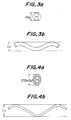
- the forming rate of the core filament is defined as follows: A theoretical diameter of the core is defined as 2Dc by a maximum sectional width of two core filaments closely arranged as shown in Fig. 3a. After the sheath composed of the steel cords is removed, one core filament 1 is taken out without being permanently deformed. Then, a maximum height Lc (core-formed amount) of the wavy filament as shown in Fig. 3b is measured by using a magnifying glass.
- the forming rate of the sheath filament is defined as follows: A theoretical diameter of the sheath is defined as 2(Dc + Ds) by a maximum sectional width of the sheath and core filaments closely arranged in series as shown in Fig. 4a. One sheath filament of the steel cord is taken out without being permanently deformed. Then, a maximum height Ls (sheath-formed amount) of the wavy filament as shown in Fig. 4b is measured by using a magnifying glass.
- the content of carbon in the steel cord is preferably from 0.80 to 0.85% by weight, when the cord is applied to a belt layer in a heavy duty pneumatic radial tire such as a bus or a truck.
- the 2 + 8 cord construction from the standpoint of increasing specific strength of the steel cord and reducing the weight of a rubber product.
- the reason why the steel cord-twisted construction is limited to the core-sheath double layer structure having the 2 + 7 or 2 + 8 two-layer cord construction is that the 2 + 7 cord construction or the 2 + 8 cord construction is the most suitable among the 2 + n cord constructions as a cord construction which advantageously allows rubber to sufficiently penetrate into gaps between the filaments of the sheath in the steel cord and is advantageous in terms of specific strength and fatigue resistance.
- the twisted construction is a cord construction of 2+6 or less, sufficient gaps can be ensured to penetrate rubber into the cord.
- the diameter of the filaments in order to obtain the same cord tenacity as that of the 2+7 or 2+8 cord construction, it is necessary to increase the diameter of the filaments as compared with the 2 + 8 cord construction. This deteriorates specific strength and fatigue resistance.
- the twisted struction is the 2 + 9 cord construction, filaments are likely to adhere to one another due to the greater number of the sheath filaments, even when the cord is formed. Consequently, rubber cannot sufficiently penetrate into the cord.
- the filaments in the core in the same direction as that in the sheath.
- the twisting direction differs between the filaments in the core and those in the sheath, the contact pressure among the filaments becomes greater as compared with the twisting in the same direction. Accordingly, fretting is likely to occur, fatigue resistance greatly drops, and tenacity-maintaining percentage is also lowered.
- the forming rate of the filaments of the sheath is less than 102%, the gaps between the adjacent filaments of the sheath are so narrow that it is likely that a portion is formed where sufficient rubber does not penetrate into the the cord.
- the forming rate of the filaments is more than 115%, the gaps between adjacent filaments in the sheath are so great that the sheath filaments closely adhere to one another without being restrained by the core. Consequently, a portion where no rubber penetrates (as illustrated by a shadowed portion in Fig. 5) is likely to be formed.
- the forming rate of the core filament is less than 103%, the sheath cannot be sufficiently restrained. Consequently, as shown in Fig. 5, there is the possibility that an annular closed space into which no rubber penetrates is formed.
- the forming rate of the core filaments is more than 120%, problems such as bending deformation of the cords are likely to occur in the production of the cord.
- the forming rate Rc of the filaments in the core is preferably 103 to 115%, and the forming rate of the filaments of the sheath is preferably 102 to 108%.
- the forming rate Rc of the filaments of the core and the forming rate Rs of the filaments of the sheath preferably satisfies the relationship: Rc ⁇ Rs. Further, it is most preferable that Rc > Rs.
- the steel cords according to the present invention can be suitably used for the belt layer of a pneumatic radial tire.
- Heavy duty pneumatic radial tires 6 having a size of 1000 R 20 as shown in Fig. 6 were used as rubber articles for evaluating steel cords.
- the tire possessed four belt plies 7 through 10, and test steel cords were used in second and third belt plies 8 and 9.
- the cord-arrayed angle was 20° toward the right side and 20° toward the left side from the circumferential direction for the second and third belt plies, respectively.
- the number of cords per 5 cm was 18.6 for both the second and third belt plies.
- the forming rate and the corrosion-propagating resistance of the steel cord, and cut separation resistance of the tire were determined or evaluated as follows.
- a rubberized steel cord taken out from the belt layer of a tire was immersed into nitrobenzene, and was boiled for 2 to 3 hours to completely peel off rubber. Then, the forming ratio was determined according to the above-mentioned definition. At that time, opposite ends of the steel cord were bent before removing the rubber to prevent unwinding of the cord, and the measurement was effected at a location of the cord upon which the bending had no influence.
- CEC cut end corrosion
- Cut separation resistance was evaluated according to a corrosion-propagating drum test method. That is, holes were formed by a drill at three locations in each of twelve kinds of tires prepared by trial to reach a second or third belt ply counted from an inner surface of the tire, and water was sealingly charged into a tire tube. Then, the tire was assembled onto a rim. Then, the tire was run on a drum over 20,000 km, and the tire was decomposed. Cut separation resistance was evaluated by a maximum peeled length of an adhesive due to corrosion of the cord.
Landscapes
- Engineering & Computer Science (AREA)
- Mechanical Engineering (AREA)
- Ropes Or Cables (AREA)
- Tires In General (AREA)
- Reinforced Plastic Materials (AREA)
Claims (11)
- Câblé en acier ayant une structure double noyau-gaine avec une configuration à 2 + 7 câblés ou une configuration à 2 + 8 câblés, dans lequel le sens de torsion du noyau est le même que celui de la gaine, caractérisé en ce que le taux de déformation Rc des filaments (1) du noyau est compris entre 103 et 120%, le taux de déformation des filaments (2) de la gaine étant compris entre 102 et 115%.
- Câblé en acier selon la revendication 1, caractérisé en ce que la teneur en carbone du câblé en acier représente de 0,80 à 0,85% en poids.
- Câblé en acier selon les revendications 1 ou 2, caractérisé par une configuration à 2 + 8 câblés.
- Câblé en acier selon l'une quelconque des revendications 1 à 3, caractérisé en ce que le taux de déformation Rc des filaments dans le noyau est compris entre 103 et 115%.
- Câblé en acier selon l'une quelconque des revendications 1 à 4, caractérisé en ce que le taux de déformation Rs des filaments de la gaine est compris entre 102 et 108%.
- Câblé en acier selon l'une quelconque des revendications 1 à 5, caractérisé en ce que le taux de déformation Rc des filaments du noyau et le taux de déformation Rs des filaments de la gaine satisfont à la relation selon laquelle Rc est supérieur ou égal à Rs.
- Câblé en acier selon la revendication 6, caractérisé en ce que Rc est supérieur à Rs.
- Câblé en acier selon l'une quelconque des revendications 1 à 7, caractérisé en ce que le diamètre Dc du filament du noyau et le diamètre Ds du filament de la gaine sont compris dans un intervalle allant de 0,26 à 0,42 mm.
- Câblé en acier selon l'une quelconque des revendications 1 à 8, caractérisé en ce que

- Câblé en acier selon l'une quelconque des revendications 1 à 9, caractérisé en ce que le diamètre des filaments du noyau et de la gaine correspond respectivement à 0,40 mm et à 0,34 mm; en ce que le pas des filaments du noyau et de la gaine correspond respectivement à Pc = 5 à 14 mm et à Ps = 12 à 30 mm; et en ce que le rapport Ps/Pc entre le pas des filaments de la gaine et le pas des filaments du noyau est compris dans un intervalle allant de 1,8 à 2,2.
- Pneumatique comportant dans une de ses couches de ceinture des câblés en acier selon l'une quelconque des revendications 1 à 10.
Applications Claiming Priority (4)
| Application Number | Priority Date | Filing Date | Title |
|---|---|---|---|
| JP5029291 | 1991-02-25 | ||
| JP50292/91 | 1991-02-25 | ||
| JP314613/91 | 1991-11-28 | ||
| JP03314613A JP3100708B2 (ja) | 1991-02-25 | 1991-11-28 | ゴム物品補強用スチールコード及びこれをベルト層に用いた空気入りラジアルタイヤ |
Publications (2)
| Publication Number | Publication Date |
|---|---|
| EP0501720A1 EP0501720A1 (fr) | 1992-09-02 |
| EP0501720B1 true EP0501720B1 (fr) | 1996-05-29 |
Family
ID=26390748
Family Applications (1)
| Application Number | Title | Priority Date | Filing Date |
|---|---|---|---|
| EP19920301522 Expired - Lifetime EP0501720B1 (fr) | 1991-02-25 | 1992-02-24 | Câbles en acier pour le renforcement d'articles en caoutchouc en pneumatiques comportant de tels câbles |
Country Status (3)
| Country | Link |
|---|---|
| EP (1) | EP0501720B1 (fr) |
| DE (1) | DE69211034T2 (fr) |
| ES (1) | ES2090495T3 (fr) |
Families Citing this family (4)
| Publication number | Priority date | Publication date | Assignee | Title |
|---|---|---|---|---|
| JP6717701B2 (ja) | 2016-08-05 | 2020-07-01 | 株式会社ブリヂストン | タイヤ用スチールコードおよびこれを用いた空気入りタイヤ |
| JP6717702B2 (ja) * | 2016-08-05 | 2020-07-01 | 株式会社ブリヂストン | 空気入りタイヤ |
| JP6683570B2 (ja) * | 2016-08-05 | 2020-04-22 | 株式会社ブリヂストン | 空気入りタイヤ |
| CN109338768B (zh) * | 2018-12-03 | 2023-11-24 | 江苏兴达钢帘线股份有限公司 | 一种2+2+8×n结构的高渗胶性能钢丝帘线 |
Family Cites Families (3)
| Publication number | Priority date | Publication date | Assignee | Title |
|---|---|---|---|---|
| DE68926978T2 (de) * | 1988-05-20 | 1997-04-03 | Toyo Tire & Rubber Co | Luftreifen |
| JP2646390B2 (ja) * | 1989-02-27 | 1997-08-27 | 横浜ゴム株式会社 | 空気入りラジアルタイヤ |
| JP3045732B2 (ja) * | 1989-05-22 | 2000-05-29 | 株式会社ブリヂストン | ラジアルタイヤ |
-
1992
- 1992-02-24 EP EP19920301522 patent/EP0501720B1/fr not_active Expired - Lifetime
- 1992-02-24 DE DE1992611034 patent/DE69211034T2/de not_active Expired - Fee Related
- 1992-02-24 ES ES92301522T patent/ES2090495T3/es not_active Expired - Lifetime
Also Published As
| Publication number | Publication date |
|---|---|
| DE69211034T2 (de) | 1996-12-12 |
| DE69211034D1 (de) | 1996-07-04 |
| EP0501720A1 (fr) | 1992-09-02 |
| ES2090495T3 (es) | 1996-10-16 |
Similar Documents
| Publication | Publication Date | Title |
|---|---|---|
| US5410868A (en) | Tire cord and tire | |
| EP0460705B1 (fr) | Cordes en acier pour le renforcement de produits en caoutchouc | |
| US4836262A (en) | Metal cords and pneumatic tires using the same | |
| KR100686906B1 (ko) | 타이어 케이싱용 다층 강 케이블 및 이를 포함하는 대형 차량용 타이어 | |
| US5661965A (en) | Steel cords for the reinforcement of rubber articles and heavy duty pneumatic radial tires using the same | |
| US5584169A (en) | Steel cord | |
| EP0269036B1 (fr) | Bandage pneumatique à nappes radiales pour poids-lourds | |
| KR0134085B1 (ko) | 공기압식 레이디얼 타이어 | |
| EP0719889B1 (fr) | Câbles d'acier pour le renforcement d'articles en caoutchouc | |
| EP0543640B1 (fr) | Bandage pneumatique | |
| KR20020063611A (ko) | 타이어 카캐스용 다층 강 케이블 | |
| EP0752325A1 (fr) | Pneu a carcasse radiale | |
| US5598693A (en) | Rubber article-reinforcing steel cords and pneumatic tires using such steel cords | |
| EP0619398B1 (fr) | Câble d'acier pour le renforcement des articles en caoutchouc et bandage pneumatique radial comportant de tels câbles | |
| EP0501720B1 (fr) | Câbles en acier pour le renforcement d'articles en caoutchouc en pneumatiques comportant de tels câbles | |
| EP0372959B1 (fr) | Câblés en acier pour le renforcement d'articles en caoutchouc et pneumatiques comportant de tels câblés en acier | |
| US5213640A (en) | Rubber article-reinforcing 2+8 steel cords and pneumatic tires using such steel cords | |
| EP0893282B1 (fr) | Cordes d'acier pour le renforcement d' articles en caoutchouc et pneumatiques radiaux les utilisant | |
| JPH1161666A (ja) | ゴム物品補強用スチールコード及び空気入りタイヤ | |
| EP1001074B1 (fr) | Câbles d'acier pour le renforcement des articles en caoutchouc et pneumatiques | |
| JPH07109684A (ja) | ゴム物品補強用スチールコード及び空気入りラジアルタイヤ | |
| JP2596347Y2 (ja) | ゴム製品補強用スチールコード |
Legal Events
| Date | Code | Title | Description |
|---|---|---|---|
| PUAI | Public reference made under article 153(3) epc to a published international application that has entered the european phase |
Free format text: ORIGINAL CODE: 0009012 |
|
| AK | Designated contracting states |
Kind code of ref document: A1 Designated state(s): BE DE ES FR GB IT |
|
| 17P | Request for examination filed |
Effective date: 19921218 |
|
| 17Q | First examination report despatched |
Effective date: 19940930 |
|
| GRAH | Despatch of communication of intention to grant a patent |
Free format text: ORIGINAL CODE: EPIDOS IGRA |
|
| GRAA | (expected) grant |
Free format text: ORIGINAL CODE: 0009210 |
|
| AK | Designated contracting states |
Kind code of ref document: B1 Designated state(s): BE DE ES FR GB IT |
|
| REF | Corresponds to: |
Ref document number: 69211034 Country of ref document: DE Date of ref document: 19960704 |
|
| ITF | It: translation for a ep patent filed | ||
| ET | Fr: translation filed | ||
| REG | Reference to a national code |
Ref country code: ES Ref legal event code: FG2A Ref document number: 2090495 Country of ref document: ES Kind code of ref document: T3 |
|
| REG | Reference to a national code |
Ref country code: ES Ref legal event code: FG2A Ref document number: 2090495 Country of ref document: ES Kind code of ref document: T3 |
|
| PLBE | No opposition filed within time limit |
Free format text: ORIGINAL CODE: 0009261 |
|
| 26N | No opposition filed | ||
| REG | Reference to a national code |
Ref country code: GB Ref legal event code: IF02 |
|
| PGFP | Annual fee paid to national office [announced via postgrant information from national office to epo] |
Ref country code: GB Payment date: 20030219 Year of fee payment: 12 |
|
| PGFP | Annual fee paid to national office [announced via postgrant information from national office to epo] |
Ref country code: ES Payment date: 20030226 Year of fee payment: 12 |
|
| PGFP | Annual fee paid to national office [announced via postgrant information from national office to epo] |
Ref country code: DE Payment date: 20030306 Year of fee payment: 12 |
|
| PGFP | Annual fee paid to national office [announced via postgrant information from national office to epo] |
Ref country code: BE Payment date: 20030425 Year of fee payment: 12 |
|
| PG25 | Lapsed in a contracting state [announced via postgrant information from national office to epo] |
Ref country code: GB Free format text: LAPSE BECAUSE OF NON-PAYMENT OF DUE FEES Effective date: 20040224 |
|
| PG25 | Lapsed in a contracting state [announced via postgrant information from national office to epo] |
Ref country code: ES Free format text: LAPSE BECAUSE OF NON-PAYMENT OF DUE FEES Effective date: 20040225 |
|
| PG25 | Lapsed in a contracting state [announced via postgrant information from national office to epo] |
Ref country code: BE Free format text: LAPSE BECAUSE OF NON-PAYMENT OF DUE FEES Effective date: 20040228 |
|
| BERE | Be: lapsed |
Owner name: *BRIDGESTONE CORP. Effective date: 20040228 |
|
| PG25 | Lapsed in a contracting state [announced via postgrant information from national office to epo] |
Ref country code: DE Free format text: LAPSE BECAUSE OF NON-PAYMENT OF DUE FEES Effective date: 20040901 |
|
| GBPC | Gb: european patent ceased through non-payment of renewal fee |
Effective date: 20040224 |
|
| PG25 | Lapsed in a contracting state [announced via postgrant information from national office to epo] |
Ref country code: IT Free format text: LAPSE BECAUSE OF NON-PAYMENT OF DUE FEES;WARNING: LAPSES OF ITALIAN PATENTS WITH EFFECTIVE DATE BEFORE 2007 MAY HAVE OCCURRED AT ANY TIME BEFORE 2007. THE CORRECT EFFECTIVE DATE MAY BE DIFFERENT FROM THE ONE RECORDED. Effective date: 20050224 |
|
| REG | Reference to a national code |
Ref country code: ES Ref legal event code: FD2A Effective date: 20040225 |
|
| PGFP | Annual fee paid to national office [announced via postgrant information from national office to epo] |
Ref country code: FR Payment date: 20070208 Year of fee payment: 16 |
|
| REG | Reference to a national code |
Ref country code: FR Ref legal event code: ST Effective date: 20081031 |
|
| PG25 | Lapsed in a contracting state [announced via postgrant information from national office to epo] |
Ref country code: FR Free format text: LAPSE BECAUSE OF NON-PAYMENT OF DUE FEES Effective date: 20080229 |