EP0501802A1 - Protection de surtension à sûreté thermique - Google Patents
Protection de surtension à sûreté thermique Download PDFInfo
- Publication number
- EP0501802A1 EP0501802A1 EP92301669A EP92301669A EP0501802A1 EP 0501802 A1 EP0501802 A1 EP 0501802A1 EP 92301669 A EP92301669 A EP 92301669A EP 92301669 A EP92301669 A EP 92301669A EP 0501802 A1 EP0501802 A1 EP 0501802A1
- Authority
- EP
- European Patent Office
- Prior art keywords
- ground
- line
- contact
- surge protector
- rod
- Prior art date
- Legal status (The legal status is an assumption and is not a legal conclusion. Google has not performed a legal analysis and makes no representation as to the accuracy of the status listed.)
- Withdrawn
Links
Images


Classifications
-
- H—ELECTRICITY
- H01—ELECTRIC ELEMENTS
- H01T—SPARK GAPS; OVERVOLTAGE ARRESTERS USING SPARK GAPS; SPARKING PLUGS; CORONA DEVICES; GENERATING IONS TO BE INTRODUCED INTO NON-ENCLOSED GASES
- H01T1/00—Details of spark gaps
- H01T1/14—Means structurally associated with spark gap for protecting it against overload or for disconnecting it in case of failure
-
- H—ELECTRICITY
- H01—ELECTRIC ELEMENTS
- H01H—ELECTRIC SWITCHES; RELAYS; SELECTORS; EMERGENCY PROTECTIVE DEVICES
- H01H37/00—Thermally-actuated switches
- H01H37/02—Details
- H01H37/32—Thermally-sensitive members
-
- H—ELECTRICITY
- H01—ELECTRIC ELEMENTS
- H01H—ELECTRIC SWITCHES; RELAYS; SELECTORS; EMERGENCY PROTECTIVE DEVICES
- H01H79/00—Protective switches in which excess current causes the closing of contacts, e.g. for short-circuiting the apparatus to be protected
Definitions
- the present invention relates to apparatus for protecting telecommunications and data transmission equipment from power surges on transmission lines to which it is connected, and more particularly, to an improved power surge protector which includes a thermal failsafe mechanism for preventing failure of the protector in the open circuit state.
- Various types of power surge protectors are known and commonly used to protect sensitive electronic equipment, such as telephone and data communications equipment contained in what is usually called a central office, from power surges on transmission lines.
- the protectors are situated near the end of the transmission line to which the equipment is connected and serve to ground the transmission line in the event of voltage or current excesses of sufficient magnitude to damage the equipment.
- Solid state and gas tube type devices are commonly used to protect against voltage surges.
- the solid state devices may include one or more diodes which form a normally non-conducting circuit, that is, one which has a very high output resistance, which becomes conductive in response to voltage exceeding a given level, for example, 260 volts.
- the gas tube type devices include spaced electrodes forming a gap. The gap is bridged by a spark when excess voltage occurs.
- Such devices may include a spring loaded element which is moved by the spring to connect the transmission line to ground when excess current is encountered.
- the element may consist of a wire wound bobbin fixed to a stationary member by a meltable substance such as solder. The solder melts to release the bobbin when the wire heats due to the excess current.
- these devices tend to heat up when exposed to sustained high voltages or currents. After a period of time, they may "burn out", that is, fail in the non-conducting state, creating a permanent open circuit condition. When this occurs, the communications equipment is left unprotected. If the problem is not detected and the protector replaced, the communications equipment is vulnerable to damage by a subsequent power surge.
- a thermal failsafe arrangement for providing a short circuit path to ground is disclosed in U.S. patent 4,944,003 (Meyerhoefer et al) which discloses resilient grounding elements biased to a normally open condition by a mass of fusible, insulating material on their contact ends. If the temperature in the surge protector module as a whole rises sufficiently the fusible material melts and allows the contacts to close. However, the operation of such systems is considered uncertain. Fusible material may remain between the resilient contact parts and the ground contacts they are intended to engage. Also if the fusible material subsequently solidifies it may push the contacts into the open circuit condition again.
- the preferred practice of the present invention uses a thermal failsafe arrangement which is mounted in intimate thermal contact with a solid state module providing surge voltage protection.
- the preferred device also provides heat coil assemblies for surge current protection.
- the thermal failsafe uses contact members or element made of a material having a configuration or shape memory.
- An example of such an element is disclosed in U.S. patent 4,538,201 (Wuyts et al) in which the element is mounted to the outer metallic shell of a gas discharge tube type of voltage surge protector which provides one electrode of the tube.
- the embodiment of the invention employs a configuration memory element in an arrangement that provides both intimate thermal contact with a solid state device and ensures that both sides of a transmission line are grounded should an excess temperature arise.
- a surge protector device of the kind having terminals for connection to communications equipment and to a transmission line respectively and including a circuit providing connections between said communications equipment terminals and said transmission line terminals, said circuit comprising one or more solid state elements providing voltage surge protection between the transmission line terminals and ground connection, characterised in that: said one or more solid state elements are disposed in a unitary assembly having first and second line contact members disposed on opposite sides of a ground contact member, a thermally sensitive, conductive rod having a middle portion thereof secured in intimate thermal and electrical contact with said ground contact, and having respective end portions located proximate but normally spaced from said line contacts, said rod being of a material having a thermal memory such that generation of excess heat in said assembly deforms said rod to contact both said transmission line contacts and short circuit them to the ground contact.
- surge current protection is also provided. More particularly this is done by means of heat coil assemblies.
- surge protector device of the kind for connection between a transmission line and a central office containing equipment to be protected from surges arising on the transmission line.
- the surge protector device is of the plug-in type and will be described with reference to the accompanying drawings in which:
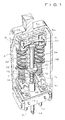
- the surge protector of the present invention includes a non-conductive housing, generally designated A.
- A Within housing A are situated a solid state, voltage sensitive device, generally designated B, a pair of current sensitive devices, generally designated C, and a thermal sensitive device, generally designated D.
- Housing A includes transmission line pins 10, 12 one for each of the ring and tip conductors of a dual transmission line.
- Each line pin 10, 12 is connected to a conductive plate 14, 16, respectively near the bottom of the housing.
- Each plate 14, 16 is in turn connected to one end of a different wire coil 18, 20, respectively, wound around a bobbin 22, 24 which is fixedly mounted on pin 10, 12 by a layer of solder 26 (see Fig. 5).
- the other end of each wire coil 18, 20 is connected to a conductive plate 28, 30 each of which is in turn, connected to a separate central office pin (not shown).
- Current from each transmission line conductor normally travels through one of the line pins 10, 12, the connected wire coil 18, 20 and then to one of the central office pins (not shown).
- the associated wire coil 18, 20 will generate sufficient heat to melt solder layer 26 affixing it to its pin.
- the bobbin 22, 24 will be moved toward the bottom of the housing by the relevant one of the conductive springs 32, 34 interposed between the bobbin and the contact of voltage sensitive device B.
- each bobbin 22, 24 carries a conductive disc 36, 38 of larger diameter than the bobbin.
- Discs 36, 38 are normally situated at a position above and spaced from a conductive disc 40 fixed to a central ground member 42.
- Member 42 is, in turn, connected to a ground pin 44 which protrudes from the bottom of housing A.
- a spring 46 situated between disc 40 and cylindrical protrusion 48 on the bottom of housing A, urges ground member 42 towards the top of housing A.
- Springs 32 and 34 are conductive and also serve to electrically connect each transmission line pin with different section 48, 50 of voltage sensitive device B.
- Device B may include a single solid state voltage protective element or a separate element for each line conductor.
- Springs 32 and 34, as well as spring 46, also serve to maintain voltage sensitive device in position within housing A.
- Each section 48, 50 of voltage sensitive device B is provided with an external conductive plate 52, 54 with a raised contact 56, 58.
- Plate 52 (and contact 56) are electrically connected to spring 32 by a conductive disc seated in the upper end of the spring and urged against an under-portion of plate 52.
- plate 54 (and contact 58) are electrically connected to spring 34 by a conductive disc seated in the upper end of the spring and urged against an under-portion of plate 54.
- Ground member 42 is connected to the ground terminal of device B on the bottom surface thereof by a disc 43.
- Conductive plate 60 on the front of device B is connected to disc 43.
- the conductive parts providing the above contacts are generally U-shaped and the device B sits snugly therein to form a unitary voltage protection assembly or module.
- the device B of generally rectangular cross-section is provided with contact metallisation in contact with the inner surfaces of these parts.
- the three conductive parts provide the contact plates 52, 54, 60 in a substantially co-planar array along one side of the device B. This enables a thermal failsafe arrangement to be provided as will be described below.
- the three contact parts also have respective portions extending under the device at an angle to portions 52, 54, 60. More particularly these portions under the device are at right angles to the plates and provide the means whereby contact from the line and ground pins is made to the voltage protection assembly, and also through which spring pressure is applied to the assembly to retain it in the housing.
- the assembly is urged upwards as seen in the drawings so that the upper surface of the device B locates against locating mouldings on the inside surface of the top wall of the housing.
- the thermal failsafe arrangement D for the voltage protective assembly comprises a conductive rod 62 composed of a nickel/titanium alloy of known composition which has a configuration memory. With normal operating temperature ranges, rod 62 has an arcuate configuration, as best seen in Fig. 4. The mid section of rod 62 is attached to plate 60 by a crimping member 64 to ground the rod and to ensure intimate thermal contact with the solid state protective device B. The ends of rod 62 each align with but, in the normal operating temperature range configuration, are spaced from contacts 56 and 58 respectively by the symmetrically bowed shape of the rod 62.
- thermal sensitive element D changes configuration is set (by choosing the appropriate alloy composition and physical characteristics) at a level substantially below that at which device B or devices C will "burn out” and fail in an open circuit condition.
- protection of the communications equipment is always assured by providing a permanent, independent path to ground which is temperature sensitive. This function is performed in an extremely reliable way by means of a simple, nickel/titanium alloy rod with configuration memory.
- surge protector for telecommunications or data transmission systems which includes a failsafe mechanism which prevents failure in the open circuit condition.
- the failsafe mechanism includes a thermal detector in the form of a rod composed of an alloy with a configuration memory. The rod abruptly and permanently changes configuration if the protector devices heat beyond a level where they are likely to fail in a non-conductive state. The configuration change creates an independent path to ground, so that the communications equipment in a central office is not left exposed to damage from further power surges on a transmission line.
- the device B may use a single solid state element or more than one.
- a single element is a two-terminal thyristor or similar voltage breakdown device which is connected in a bridge configuration of the kind exemplified by Fig. 8 of U.S. patent 4,796,150.
- An example of the use of more than one voltage breakdown element is a pair of back-to-back thyristors connected between the line contacts and with their mid-point connected to the ground contact.
- the mechanical and electrical assembly of the described surge protector device is considered two have advantages.
- the circuit is of the general kind shown in Fig. 1 of U.S. patent 4,944,003.
- the heat coils 18 and 20 of the above described embodiment are connected between respective line pins and central office pins of the plug-in device.
- the line discs 36 and 38 together with ground disc 40 provide a short circuit to ground upon excess current flowing through one or other heat coil.
- the solid state voltage device B is connected between the line pins by connections made through the conductive springs 32, 34 which also mechanically bias the voltage protection assembly into position at the top of the housing A and provide the operating bias for the heat coil assemblies.
- the failsafe contacts are provided by rod 62 between ground and the respective line contacts 56, 58 of the device B but in the embodiment of the invention described the failsafe arrangement D has an intimate thermal contact with the device B to ensure a rapid response to excess heating of that device.
- the ground contact rod 42 leading to ground pin 44 is arranged generally parallel with springs 32 and 34, and under the action of spring 46 is not only urged into electrical contact with contact element 60 but provides additional mechanical bias locating the voltage protective assembly in position.
- the device B has been described as seated in the three contact parts for the line and ground contacts.
- the device B may be manufactured as having three integral contacts emerging from the device body normally to the plane of Fig. 2 and being bent down in the plane of the figure and then under the body to provide the portions for contacting by the springs 32, 34 and ground rod 42.
Landscapes
- Physics & Mathematics (AREA)
- Thermal Sciences (AREA)
- Emergency Protection Circuit Devices (AREA)
Applications Claiming Priority (2)
| Application Number | Priority Date | Filing Date | Title |
|---|---|---|---|
| US661216 | 1991-02-27 | ||
| US07/661,216 US5166855A (en) | 1991-02-27 | 1991-02-27 | Surge protector with thermal failsafe |
Publications (1)
| Publication Number | Publication Date |
|---|---|
| EP0501802A1 true EP0501802A1 (fr) | 1992-09-02 |
Family
ID=24652658
Family Applications (1)
| Application Number | Title | Priority Date | Filing Date |
|---|---|---|---|
| EP92301669A Withdrawn EP0501802A1 (fr) | 1991-02-27 | 1992-02-27 | Protection de surtension à sûreté thermique |
Country Status (2)
| Country | Link |
|---|---|
| US (1) | US5166855A (fr) |
| EP (1) | EP0501802A1 (fr) |
Cited By (1)
| Publication number | Priority date | Publication date | Assignee | Title |
|---|---|---|---|---|
| FR2737605A1 (fr) * | 1995-08-03 | 1997-02-07 | Europ Agence Spatiale | Commutateur de mise en court-circuit active thermiquement destine a un element de batterie |
Families Citing this family (33)
| Publication number | Priority date | Publication date | Assignee | Title |
|---|---|---|---|---|
| US5836791A (en) * | 1994-10-21 | 1998-11-17 | Psi Telecommunications, Inc. | Modular telecommunications terminal block |
| US6084761A (en) | 1998-03-09 | 2000-07-04 | Teccor Electronics, Lp | Telephone line surge protector |
| US6104591A (en) * | 1998-03-09 | 2000-08-15 | Teccor Electronics, Inc. | Telephone line protection element |
| US6184464B1 (en) * | 1998-04-27 | 2001-02-06 | Square D Company | Protective containment apparatus for potted electronic circuits |
| US6980647B1 (en) | 1999-01-12 | 2005-12-27 | Teccor Electronics, Lp | Primary telephone line protector with failsafe |
| US6118664A (en) * | 1999-01-13 | 2000-09-12 | Lucent Technologies, Inc. | Handle for plug-in protectors |
| US6144543A (en) * | 1999-06-24 | 2000-11-07 | Lucent Technologies Inc. | Grounding device |
| AU2002213354A1 (en) * | 2000-10-19 | 2002-04-29 | Porta Systems Corporation | Failsafe mechanism for telecommunications protector module |
| US6671155B2 (en) | 2001-11-30 | 2003-12-30 | Corning Cable Systems Llc | Surge protector with thermally activated failsafe mechanism |
| US20050099755A1 (en) * | 2003-11-10 | 2005-05-12 | David Martin | Broadband surge protector with non-resetting current limiter |
| CN100463323C (zh) * | 2004-12-09 | 2009-02-18 | 鸿富锦精密工业(深圳)有限公司 | 温度安全装置 |
| US20080165466A1 (en) * | 2007-01-05 | 2008-07-10 | Luke Timothy Gritter | Method and Apparatus For Providing a Carbon Nanotube Plasma Limiter Having a Subnanosecond Response Time |
| WO2009052517A2 (fr) | 2007-10-18 | 2009-04-23 | Polyphaser Corporation | Dispositif de suppression de surtension doté d'un ou de plusieurs anneaux |
| CN101836341B (zh) * | 2007-10-30 | 2013-07-03 | 特兰斯泰克塔系统公司 | 用于传递dc和rf信号的浪涌保护电路 |
| WO2009142657A1 (fr) * | 2008-05-19 | 2009-11-26 | Polyphaser Corporation | Suppresseur de surtensions à large bande laissant passer le courant continu et les radiofréquences |
| CN102742101A (zh) * | 2009-10-02 | 2012-10-17 | 特兰斯泰克塔系统公司 | 带有非线性保护装置的rf共轴浪涌保护器 |
| US8400760B2 (en) | 2009-12-28 | 2013-03-19 | Transtector Systems, Inc. | Power distribution device |
| US8441795B2 (en) | 2010-05-04 | 2013-05-14 | Transtector Systems, Inc. | High power band pass RF filter having a gas tube for surge suppression |
| US20110271802A1 (en) | 2010-05-04 | 2011-11-10 | Edward Honig | Double handle tool |
| CA2798891C (fr) | 2010-05-11 | 2016-04-12 | Transtector Systems, Inc. | Protecteur rf laissant passer le continu et muni d'un module limiteur de surcharge |
| US8611062B2 (en) | 2010-05-13 | 2013-12-17 | Transtector Systems, Inc. | Surge current sensor and surge protection system including the same |
| US8976500B2 (en) | 2010-05-26 | 2015-03-10 | Transtector Systems, Inc. | DC block RF coaxial devices |
| US8730637B2 (en) | 2010-12-17 | 2014-05-20 | Transtector Systems, Inc. | Surge protection devices that fail as an open circuit |
| US9054514B2 (en) | 2012-02-10 | 2015-06-09 | Transtector Systems, Inc. | Reduced let through voltage transient protection or suppression circuit |
| US9048662B2 (en) | 2012-03-19 | 2015-06-02 | Transtector Systems, Inc. | DC power surge protector |
| US9190837B2 (en) | 2012-05-03 | 2015-11-17 | Transtector Systems, Inc. | Rigid flex electromagnetic pulse protection device |
| US9124093B2 (en) | 2012-09-21 | 2015-09-01 | Transtector Systems, Inc. | Rail surge voltage protector with fail disconnect |
| US10129993B2 (en) | 2015-06-09 | 2018-11-13 | Transtector Systems, Inc. | Sealed enclosure for protecting electronics |
| US10588236B2 (en) | 2015-07-24 | 2020-03-10 | Transtector Systems, Inc. | Modular protection cabinet with flexible backplane |
| US10356928B2 (en) | 2015-07-24 | 2019-07-16 | Transtector Systems, Inc. | Modular protection cabinet with flexible backplane |
| US9924609B2 (en) | 2015-07-24 | 2018-03-20 | Transtector Systems, Inc. | Modular protection cabinet with flexible backplane |
| US10193335B2 (en) | 2015-10-27 | 2019-01-29 | Transtector Systems, Inc. | Radio frequency surge protector with matched piston-cylinder cavity shape |
| US9991697B1 (en) | 2016-12-06 | 2018-06-05 | Transtector Systems, Inc. | Fail open or fail short surge protector |
Citations (3)
| Publication number | Priority date | Publication date | Assignee | Title |
|---|---|---|---|---|
| US4538201A (en) * | 1983-05-02 | 1985-08-27 | International Standard Electric Corporation | Surge protector |
| US4796150A (en) * | 1987-04-16 | 1989-01-03 | American Telephone And Telegraph Company, At&T Bell Laboratories | Telecommunication protector unit with pivotal surge protector |
| US4944003A (en) * | 1989-09-28 | 1990-07-24 | Porta Systems Corp. | Solid state telephone protector module |
Family Cites Families (5)
| Publication number | Priority date | Publication date | Assignee | Title |
|---|---|---|---|---|
| US3893055A (en) * | 1973-04-16 | 1975-07-01 | Texas Instruments Inc | High gain relays and systems |
| US4249224A (en) * | 1979-03-07 | 1981-02-03 | Reliable Electric Company | Surge voltage arrester with fail-safe feature |
| EP0353816B1 (fr) * | 1988-08-01 | 1993-12-22 | Matsushita Electric Works, Ltd. | Alliage en mémoire de forme et dispositif de détection pour circuit électrique utilisant cet alliage |
| US4856060A (en) * | 1988-08-01 | 1989-08-08 | Porta Systems Corp. | Solid state telephone protector module |
| US4958253A (en) * | 1989-10-25 | 1990-09-18 | Reliance Comm/Tec Corporation | Line protector for a communications circuit |
-
1991
- 1991-02-27 US US07/661,216 patent/US5166855A/en not_active Expired - Fee Related
-
1992
- 1992-02-27 EP EP92301669A patent/EP0501802A1/fr not_active Withdrawn
Patent Citations (3)
| Publication number | Priority date | Publication date | Assignee | Title |
|---|---|---|---|---|
| US4538201A (en) * | 1983-05-02 | 1985-08-27 | International Standard Electric Corporation | Surge protector |
| US4796150A (en) * | 1987-04-16 | 1989-01-03 | American Telephone And Telegraph Company, At&T Bell Laboratories | Telecommunication protector unit with pivotal surge protector |
| US4944003A (en) * | 1989-09-28 | 1990-07-24 | Porta Systems Corp. | Solid state telephone protector module |
Cited By (2)
| Publication number | Priority date | Publication date | Assignee | Title |
|---|---|---|---|---|
| FR2737605A1 (fr) * | 1995-08-03 | 1997-02-07 | Europ Agence Spatiale | Commutateur de mise en court-circuit active thermiquement destine a un element de batterie |
| US5898356A (en) * | 1995-08-03 | 1999-04-27 | Agence Spatiale Europeenne | Thermally-activated switch for short-circuiting a battery cell |
Also Published As
| Publication number | Publication date |
|---|---|
| US5166855A (en) | 1992-11-24 |
Similar Documents
| Publication | Publication Date | Title |
|---|---|---|
| EP0501802A1 (fr) | Protection de surtension à sûreté thermique | |
| US4796150A (en) | Telecommunication protector unit with pivotal surge protector | |
| US4876621A (en) | Line protector for a communications circuit | |
| EP0017324A1 (fr) | Dispositif dérivant les surtensions avec un dispositif protecteur contre les pannes | |
| US4161762A (en) | Gas tube arrester protector and method of assembling the protector | |
| US4958254A (en) | Five pin protector module for telephone circuits | |
| US4723190A (en) | Safety device communication equipment | |
| US4275432A (en) | Thermal switch short circuiting device for arrester systems | |
| CA2176772C (fr) | Dispositif de protection | |
| CA2125453C (fr) | Protection contre les surtensions | |
| US20040228064A1 (en) | Central office surge protector with interacting varistors | |
| US4424546A (en) | Miniature central office surge protectors | |
| KR101681394B1 (ko) | 회로 보호 장치 | |
| US4736269A (en) | Voltage surge limiter with grounding assembly | |
| US5027100A (en) | Gas tube fail safe device for telephone protector modules | |
| US4307430A (en) | Protector device for telecommunications circuits | |
| US4866563A (en) | Transient suppressor device assembly | |
| CA2072419C (fr) | Rupteur thermique et circuit d'absorption de surtensions | |
| US5991136A (en) | Protector unit | |
| EP0475954B1 (fr) | Equipement de protection contre les surcharges pour systemes de telecommunications | |
| US4434449A (en) | Protector unit for telecommunications circuits | |
| KR101458720B1 (ko) | 열적으로 퓨징되는 mov 장치 및 이를 포함하는 회로 | |
| US5155650A (en) | Thyristor fail-safe | |
| US5438619A (en) | Solid state primary telephone protector | |
| US5210677A (en) | Solid state station protectors |
Legal Events
| Date | Code | Title | Description |
|---|---|---|---|
| PUAI | Public reference made under article 153(3) epc to a published international application that has entered the european phase |
Free format text: ORIGINAL CODE: 0009012 |
|
| AK | Designated contracting states |
Kind code of ref document: A1 Designated state(s): DE FR GB IT |
|
| 18D | Application deemed to be withdrawn |
Effective date: 19930303 |