EP0501852A1 - Vorrichtung zur Befestigung eines rohrförmigen Organs auf einem Rohrende eines Kupplungsteils, insbesondere eines Kraftfahrzeuges - Google Patents
Vorrichtung zur Befestigung eines rohrförmigen Organs auf einem Rohrende eines Kupplungsteils, insbesondere eines Kraftfahrzeuges Download PDFInfo
- Publication number
- EP0501852A1 EP0501852A1 EP92400443A EP92400443A EP0501852A1 EP 0501852 A1 EP0501852 A1 EP 0501852A1 EP 92400443 A EP92400443 A EP 92400443A EP 92400443 A EP92400443 A EP 92400443A EP 0501852 A1 EP0501852 A1 EP 0501852A1
- Authority
- EP
- European Patent Office
- Prior art keywords
- sleeve
- branches
- end piece
- tubular member
- external
- Prior art date
- Legal status (The legal status is an assumption and is not a legal conclusion. Google has not performed a legal analysis and makes no representation as to the accuracy of the status listed.)
- Granted
Links
- 230000008878 coupling Effects 0.000 title 1
- 238000010168 coupling process Methods 0.000 title 1
- 238000005859 coupling reaction Methods 0.000 title 1
- 238000007789 sealing Methods 0.000 claims abstract description 8
- 238000001816 cooling Methods 0.000 description 7
- XLYOFNOQVPJJNP-UHFFFAOYSA-N water Substances O XLYOFNOQVPJJNP-UHFFFAOYSA-N 0.000 description 3
- 238000006073 displacement reaction Methods 0.000 description 1
- 230000000694 effects Effects 0.000 description 1
- 238000012423 maintenance Methods 0.000 description 1
- 230000014759 maintenance of location Effects 0.000 description 1
- 230000035515 penetration Effects 0.000 description 1
Images
Classifications
-
- F—MECHANICAL ENGINEERING; LIGHTING; HEATING; WEAPONS; BLASTING
- F16—ENGINEERING ELEMENTS AND UNITS; GENERAL MEASURES FOR PRODUCING AND MAINTAINING EFFECTIVE FUNCTIONING OF MACHINES OR INSTALLATIONS; THERMAL INSULATION IN GENERAL
- F16L—PIPES; JOINTS OR FITTINGS FOR PIPES; SUPPORTS FOR PIPES, CABLES OR PROTECTIVE TUBING; MEANS FOR THERMAL INSULATION IN GENERAL
- F16L37/00—Couplings of the quick-acting type
- F16L37/08—Couplings of the quick-acting type in which the connection between abutting or axially overlapping ends is maintained by locking members
- F16L37/084—Couplings of the quick-acting type in which the connection between abutting or axially overlapping ends is maintained by locking members combined with automatic locking
- F16L37/098—Couplings of the quick-acting type in which the connection between abutting or axially overlapping ends is maintained by locking members combined with automatic locking by means of flexible hooks
- F16L37/0985—Couplings of the quick-acting type in which the connection between abutting or axially overlapping ends is maintained by locking members combined with automatic locking by means of flexible hooks the flexible hook extending radially inwardly from an outer part and engaging a bead, recess or the like on an inner part
-
- F—MECHANICAL ENGINEERING; LIGHTING; HEATING; WEAPONS; BLASTING
- F16—ENGINEERING ELEMENTS AND UNITS; GENERAL MEASURES FOR PRODUCING AND MAINTAINING EFFECTIVE FUNCTIONING OF MACHINES OR INSTALLATIONS; THERMAL INSULATION IN GENERAL
- F16L—PIPES; JOINTS OR FITTINGS FOR PIPES; SUPPORTS FOR PIPES, CABLES OR PROTECTIVE TUBING; MEANS FOR THERMAL INSULATION IN GENERAL
- F16L37/00—Couplings of the quick-acting type
- F16L37/08—Couplings of the quick-acting type in which the connection between abutting or axially overlapping ends is maintained by locking members
- F16L37/084—Couplings of the quick-acting type in which the connection between abutting or axially overlapping ends is maintained by locking members combined with automatic locking
- F16L37/0842—Couplings of the quick-acting type in which the connection between abutting or axially overlapping ends is maintained by locking members combined with automatic locking by means of a ring which is split into a plurality of component parts which are held in place by means of a resilient ring member
-
- F—MECHANICAL ENGINEERING; LIGHTING; HEATING; WEAPONS; BLASTING
- F28—HEAT EXCHANGE IN GENERAL
- F28F—DETAILS OF HEAT-EXCHANGE AND HEAT-TRANSFER APPARATUS, OF GENERAL APPLICATION
- F28F9/00—Casings; Header boxes; Auxiliary supports for elements; Auxiliary members within casings
- F28F9/02—Header boxes; End plates
- F28F9/0246—Arrangements for connecting header boxes with flow lines
- F28F9/0256—Arrangements for coupling connectors with flow lines
Definitions
- the present invention relates to a device for fixing a tubular member to a tubular end piece for connecting a component, usable in particular in the automotive industry.
- the device according to the invention can thus be used for example for the connection of a cooling radiator to a motor vehicle engine.
- Modern motor vehicles have an increasingly tapered hood for improving the vehicle's air penetration coefficient.
- the space available under the hood for the radiator is therefore reduced compared to older vehicles.
- the water in the cooling circuit is therefore relatively less cooled on modern vehicles and this water is found during the running of the vehicle, at a pressure and at a temperature substantially higher than the pressure and the temperature of the water in the circuits. for cooling older vehicles.
- connection conduit or flexible connector is engaged on the corresponding rigid end piece and fixed in leaktight manner on this end piece by means of a clamping collar disposed around the flexible connection.
- the cable ties used can be of different types.
- Rack clamps can also be used, but these clamps also require the use of specific tools for their assembly and disassembly.
- the devices for joining the cooling circuits in which the flexible connections are threaded onto the rigid ends of the circuit and tightened by clamps are therefore not satisfactory under current conditions and a fortiori in the case of cooling circuits operating under high pressure.
- these devices cannot be mounted automatically.
- the object of the invention is therefore to solve these problems.
- the subject of the invention is a device for fixing a tubular member to a tubular end piece for connecting a component, in particular of a motor vehicle, in which the tubular member is fixed to the end piece via holding and sealing means, characterized in that the holding and sealing means comprise two sleeves coaxial with the end piece, one of which, external, is connected to the component, and comprises elastically deformable branches, stressed in direction of the nozzle, at the end of each of which is provided a projecting hooking portion towards the inside of the sleeve, and the other internal has a stop surface, and is mounted axially displaceable between the external sleeve and the end piece by pressing the tubular member on the stop surface of the latter, between a mounting position, in which this internal sleeve keeps the branches of the external sleeve away from the end piece and a hooking position in which this internal sleeve releases the branches of the external sleeve, so that the hooking portions thereof cooperate with the tubular member to maintain it in position
- the fixing device according to the invention can be used to fix a tubular member 1 on a tubular end piece 2 for connecting a component 3, in particular of a motor vehicle.
- this device can be used for fixing one end of a flexible connection conduit, the other end of which is connected to a motor vehicle engine, on a rigid end piece of a radiator for cooling that -this.
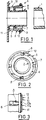
- the tubular member 1 is fixed to the end piece by means of holding and sealing means designated by the general reference 4 in these figures.
- these holding and sealing means comprise two sleeves 5 and 6 coaxial with the end piece, one of which is external 5, is connected to component 3 and the other is internal 6, is mounted axially displaceable between the external sleeve 5 and the connection piece 2.
- the internal sleeve 6 has an abutment surface 7 provided for example at one of its ends and for example abutment portions, 8 and 9, at its other end, the function of which will be described in more detail below.
- the outer sleeve 5 has branches, for example 10 and 11, which are elastically deformable and urged towards the end piece 2.
- This sleeve can for example have four branches at 90 ° relative to one another.
- These branches can for example be biased towards the endpiece by means of an elastic ring 12 disposed around the corresponding end thereof.
- each of these branches of the external sleeve 5 comprises a hooking portion 10a, 11a for example, projecting towards the inside of the sleeve.
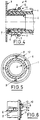
- the internal sleeve 6 is mounted to move axially between the external sleeve 5 and the end piece 2, by support of the member tubular 1 and more particularly of the end of the latter on the abutment surface 7 of this internal sleeve 6, between a mounting position of the tubular member around the end piece, shown in FIGS. 1 to 3, in which the abutment portions 8, 9 of this internal sleeve 6 extend between the ends of the branches of the external sleeve at the hooking parts thereof, to keep the branches of the external sleeve away from the end piece and thus allowing the engagement of the tubular member 1 around the end piece 2 and a hooking position, shown in FIGS. 4 to 6, in which the abutment portions 8 and 9 of the internal sleeve release the branches of the sleeve external, so that the projecting parts of these cooperate with the tubular connection in order to maintain it in position on the end piece.
- the abutment portions 8, 9 of this inner sleeve 6 extend, in the mounting position of the inner sleeve, between bosses 10b and 11b (Fig. 3) projecting laterally from the corresponding ends of the arms 10 and 11 of the outer sleeve 5. This keeps these branches in a position remote from the nozzle 2 to allow the passage of the tubular member around it.
- the internal sleeve 6 advantageously comprises 4 abutment portions each extending between two successive branches of the external sleeve.
- the projecting parts 10a and 11a for hooking these branches may have inclined faces facilitating engagement and improving the retention of the tubular member on the end piece.
- the external sleeve in the mounting position, has a generally frustoconical shape open in the direction of the tubular member to facilitate its engagement on the nozzle.
- the internal sleeve 6 has abutment portions 8 and 9 for holding or releasing the arms 10 and 11 from the external sleeve 5, this maintenance in the remote position and this release can be achieved by any other part of the internal sleeve such as for example an end portion thereof on which the hooking protruding parts 10a and 11a of the arms 10 and 11 of the outer sleeve 5 come to bear, in the mounting position.
Landscapes
- Engineering & Computer Science (AREA)
- General Engineering & Computer Science (AREA)
- Mechanical Engineering (AREA)
- Physics & Mathematics (AREA)
- Thermal Sciences (AREA)
- Quick-Acting Or Multi-Walled Pipe Joints (AREA)
- Clamps And Clips (AREA)
Applications Claiming Priority (2)
| Application Number | Priority Date | Filing Date | Title |
|---|---|---|---|
| FR9102038A FR2672959B1 (fr) | 1991-02-20 | 1991-02-20 | Dispositif de fixation d'un organe tubulaire sur un embout tubulaire de raccordement d'un composant, notamment de vehicule automobile. |
| FR9102038 | 1991-02-20 |
Publications (2)
| Publication Number | Publication Date |
|---|---|
| EP0501852A1 true EP0501852A1 (de) | 1992-09-02 |
| EP0501852B1 EP0501852B1 (de) | 1995-01-18 |
Family
ID=9409931
Family Applications (1)
| Application Number | Title | Priority Date | Filing Date |
|---|---|---|---|
| EP92400443A Expired - Lifetime EP0501852B1 (de) | 1991-02-20 | 1992-02-19 | Vorrichtung zur Befestigung eines rohrförmigen Organs auf einem Rohrende eines Kupplungsteils, insbesondere eines Kraftfahrzeuges |
Country Status (6)
| Country | Link |
|---|---|
| US (1) | US5297823A (de) |
| EP (1) | EP0501852B1 (de) |
| CA (1) | CA2061586C (de) |
| DE (1) | DE69201203T2 (de) |
| ES (1) | ES2070595T3 (de) |
| FR (1) | FR2672959B1 (de) |
Cited By (2)
| Publication number | Priority date | Publication date | Assignee | Title |
|---|---|---|---|---|
| EP0654648A3 (de) * | 1993-11-24 | 1995-11-02 | Gen Motors Corp | Wärmetauscher. |
| FR3060069A1 (fr) * | 2016-12-13 | 2018-06-15 | Airbus Operations Sas | Bielle amortissante convertible en bielle rigide |
Families Citing this family (14)
| Publication number | Priority date | Publication date | Assignee | Title |
|---|---|---|---|---|
| US5556136A (en) * | 1995-04-25 | 1996-09-17 | Von Berg; Peter | Connector for flexible medical tubing |
| DE19518628C1 (de) * | 1995-05-20 | 1996-09-26 | Rasmussen Gmbh | Haltevorrichtung zur Lagesicherung einer Schlauchschelle |
| DE29603304U1 (de) * | 1996-02-23 | 1996-04-11 | Reiku GmbH, 51674 Wiehl | Schlauchfassung, insbesondere für Wellrohre |
| KR200162382Y1 (ko) * | 1996-08-20 | 1999-12-15 | 윤종용 | 모니터의 비데오 pcb 어셈블리 결착장치 |
| GB9822995D0 (en) * | 1998-10-22 | 1998-12-16 | Britax Wingard Ltd | Vehicle exterior mirror |
| DE102004062887B3 (de) * | 2004-12-27 | 2005-10-13 | A. Raymond & Cie | Kupplung |
| FR2881811B1 (fr) * | 2005-02-10 | 2007-04-20 | Legris Sa | Dispositif de raccordement instantane avec moyen de verrouillage et/ou de deconnexion |
| FR2893380B1 (fr) * | 2005-11-15 | 2009-02-27 | Legris Sa | Organe de retenue a dimension reduite pour ancrage d'un tube dans un element de circuit et element de circuit correspondant |
| DE102006047267B4 (de) * | 2006-10-04 | 2010-02-04 | A. Raymond Et Cie | Kupplungsteil für eine Fluidleitungskupplung |
| DE102013223241B4 (de) * | 2013-11-14 | 2021-12-09 | Eberspächer Climate Control Systems GmbH | Wärmeträgermediumanschlussbaugruppe, insbesondere für eine Wärmetauscheranordnung eines Fahrzeugheizgeräts |
| US9444124B2 (en) * | 2014-01-23 | 2016-09-13 | Lg Chem, Ltd. | Battery cell assembly and method for coupling a cooling fin to first and second cooling manifolds |
| EP3444557B1 (de) * | 2017-08-17 | 2023-03-29 | Valeo Autosystemy SP. Z.O.O. | Wärmetauscher mit verstärkungsmittel |
| US10857433B2 (en) | 2018-01-31 | 2020-12-08 | Breakthrough Golf Technology, Llc | Golf shaft system and golf shaft |
| US10213666B1 (en) | 2018-01-31 | 2019-02-26 | Breakthrough Golf Technology Llc | Golf shaft |
Citations (2)
| Publication number | Priority date | Publication date | Assignee | Title |
|---|---|---|---|---|
| US3439944A (en) * | 1965-07-16 | 1969-04-22 | Bernhard Leutenegger | Nipple for pipe joints |
| EP0373920A1 (de) * | 1988-12-16 | 1990-06-20 | Parker Enzed (N.Z.) Limited | Schnellverbindungs- und Trennkupplung für Fluide |
Family Cites Families (11)
| Publication number | Priority date | Publication date | Assignee | Title |
|---|---|---|---|---|
| NL86404C (de) * | ||||
| US2465197A (en) * | 1945-08-25 | 1949-03-22 | Newton L Chatham | Coupling |
| US3887222A (en) * | 1974-07-25 | 1975-06-03 | Hansen Mfg | Coupling with push-pull release |
| NO161142C (no) * | 1978-03-13 | 1989-07-05 | Wavin Bv | Roerdel med en muffeende og et i denne anordnet tetningsorgan som er understoettet av en stoettering. |
| CH665700A5 (de) * | 1984-07-10 | 1988-05-31 | Cejn Ag | Loesbare steckmuffen-rohrverbindung. |
| US4691943A (en) * | 1985-04-24 | 1987-09-08 | Schmelzer Corporation | Quick connect fluid fitting assembly |
| SE451342B (sv) * | 1985-11-21 | 1987-09-28 | Weimar Ohlsson | Snabbkoppling for sammankoppling av tva hogtrycksfluidledningar |
| JPH0317112Y2 (de) * | 1987-05-29 | 1991-04-11 | ||
| US5033777A (en) * | 1987-09-15 | 1991-07-23 | Colder Products Company | Male insert member having integrally molded part line free seal |
| US5005877A (en) * | 1988-12-16 | 1991-04-09 | Parker Hannifin Corporation | Quick connect/disconnect fluid coupling |
| DK0401083T3 (da) * | 1989-05-29 | 1994-04-25 | Autobrevets | Indretning for tilvejebringelse af en tæt samling mellem et rør og en slange |
-
1991
- 1991-02-20 FR FR9102038A patent/FR2672959B1/fr not_active Expired - Fee Related
-
1992
- 1992-02-19 EP EP92400443A patent/EP0501852B1/de not_active Expired - Lifetime
- 1992-02-19 DE DE69201203T patent/DE69201203T2/de not_active Expired - Fee Related
- 1992-02-19 ES ES92400443T patent/ES2070595T3/es not_active Expired - Lifetime
- 1992-02-19 US US07/836,833 patent/US5297823A/en not_active Expired - Lifetime
- 1992-02-20 CA CA002061586A patent/CA2061586C/en not_active Expired - Fee Related
Patent Citations (2)
| Publication number | Priority date | Publication date | Assignee | Title |
|---|---|---|---|---|
| US3439944A (en) * | 1965-07-16 | 1969-04-22 | Bernhard Leutenegger | Nipple for pipe joints |
| EP0373920A1 (de) * | 1988-12-16 | 1990-06-20 | Parker Enzed (N.Z.) Limited | Schnellverbindungs- und Trennkupplung für Fluide |
Non-Patent Citations (1)
| Title |
|---|
| MACHINE DESIGN vol. 53, no. 24, Octobre 1981, CLEVELAND, OHIO, US page 46; 'PUSH-IN FITTING SEALS PNEUMATIC TUBING' * |
Cited By (2)
| Publication number | Priority date | Publication date | Assignee | Title |
|---|---|---|---|---|
| EP0654648A3 (de) * | 1993-11-24 | 1995-11-02 | Gen Motors Corp | Wärmetauscher. |
| FR3060069A1 (fr) * | 2016-12-13 | 2018-06-15 | Airbus Operations Sas | Bielle amortissante convertible en bielle rigide |
Also Published As
| Publication number | Publication date |
|---|---|
| CA2061586A1 (en) | 1992-08-21 |
| CA2061586C (en) | 2000-04-18 |
| FR2672959B1 (fr) | 1993-06-11 |
| EP0501852B1 (de) | 1995-01-18 |
| US5297823A (en) | 1994-03-29 |
| DE69201203D1 (de) | 1995-03-02 |
| DE69201203T2 (de) | 1995-09-14 |
| ES2070595T3 (es) | 1995-06-01 |
| FR2672959A1 (fr) | 1992-08-21 |
Similar Documents
| Publication | Publication Date | Title |
|---|---|---|
| EP0501852B1 (de) | Vorrichtung zur Befestigung eines rohrförmigen Organs auf einem Rohrende eines Kupplungsteils, insbesondere eines Kraftfahrzeuges | |
| EP0360634B1 (de) | Verbindungseinrichtung zwischen einem Schlauchverbindungsstück und dem starren Rohrende eines Druckmittelkreislaufs | |
| EP0266270B1 (de) | Vorrichtung zur dichtenden Befestigung eines Schlauches oder Rohres auf einem Stutzen | |
| EP0621432B1 (de) | Vorrichtung zum dichten Verbinden eines Schlauches mit einem starren Rohrende | |
| FR2749639A1 (fr) | Dispositif de raccord rapide pour conduit de fluide sous pression | |
| FR2657938A1 (fr) | Raccord etanche perfectionne pour conduites de transport de fluides quelconques. | |
| FR2588354A1 (fr) | Dispositif de raccordement d'un tuyau elastiquement deformable a un tube rigide | |
| FR2950662A1 (fr) | Dispositif de fixation d'un element de forme allongee sur un carter de turbomachine | |
| FR2679313A1 (fr) | Dispositif de serrage etanche pour le serrage d'un tube flexible monte a force a l'interieur d'un raccord tubulaire. | |
| EP1291568B1 (de) | Schnellkupplung für verformbare Rohre | |
| EP0559505B1 (de) | Vorrichtung zum Verbinden eines Schlauchendes mit dem Ende eines starren Rohres, insbesondere für ein Fahrzeugskühlsystem | |
| WO2000079172A1 (fr) | Dispositif de raccord etanche pour conduit de fluide, en particulier pour vehicule automobile | |
| EP0338880B1 (de) | Verbindungseinrichtung zwischen einem schlauchartigen Verbindungsteil und einem starren Rohrende für einen Druckmittelkreislauf | |
| EP0480818B1 (de) | Verbesserte Vorrichtung zum Verbinden eines Schlauchendes mit dem Ende eines starren Rohres | |
| FR2672105A1 (fr) | Dispositif de fixation d'un organe tubulaire sur un embout tubulaire de raccordement d'un composant, notamment de vehicule automobile. | |
| FR2628504A1 (fr) | Procede et ensemble de fixation d'une extremite de tuyauterie souple a un organe complementaire | |
| FR2913088A3 (fr) | Raccord banjo pourvu d'un joint imperdable | |
| FR2950205A1 (fr) | Dispositif de raccordement d'un capteur integre a un harnais electrique pour un moteur d'avion | |
| FR2810716A1 (fr) | Dispositif d'accouplement de deux elements tubulaires formant notamment des elements d'une ligne d'echappement de vehicule automobile | |
| FR2602572A1 (fr) | Dispositif de raccordement d'un tuyau souple autour d'un embout tubulaire rigide | |
| FR2628819A1 (fr) | Dispositif de jonction entre un raccord tubulaire souple et un embout tubulaire rigide | |
| EP0360689B1 (de) | Schnellverbindung, insbesondere für Fluidleitungen in Kraftfahrzeugen | |
| EP1008796A2 (de) | Verbindungsvorrichtung für die lösbare Verbindung eines Rohres an einem Endstück mittels einer koaxialen Hülse | |
| FR2886370A1 (fr) | Dispositif de raccordement de deux elements tels qu'un conduit d'alimentation en carburant et un injecteur | |
| FR2678349A1 (fr) | Dispositif de raccordement de deux organes tubulaires. |
Legal Events
| Date | Code | Title | Description |
|---|---|---|---|
| PUAI | Public reference made under article 153(3) epc to a published international application that has entered the european phase |
Free format text: ORIGINAL CODE: 0009012 |
|
| AK | Designated contracting states |
Kind code of ref document: A1 Designated state(s): DE ES GB IT NL SE |
|
| 17P | Request for examination filed |
Effective date: 19920828 |
|
| 17Q | First examination report despatched |
Effective date: 19931022 |
|
| GRAA | (expected) grant |
Free format text: ORIGINAL CODE: 0009210 |
|
| AK | Designated contracting states |
Kind code of ref document: B1 Designated state(s): DE ES GB IT NL SE |
|
| REF | Corresponds to: |
Ref document number: 69201203 Country of ref document: DE Date of ref document: 19950302 |
|
| ITF | It: translation for a ep patent filed | ||
| GBT | Gb: translation of ep patent filed (gb section 77(6)(a)/1977) |
Effective date: 19950427 |
|
| REG | Reference to a national code |
Ref country code: ES Ref legal event code: FG2A Ref document number: 2070595 Country of ref document: ES Kind code of ref document: T3 |
|
| PLBE | No opposition filed within time limit |
Free format text: ORIGINAL CODE: 0009261 |
|
| STAA | Information on the status of an ep patent application or granted ep patent |
Free format text: STATUS: NO OPPOSITION FILED WITHIN TIME LIMIT |
|
| 26N | No opposition filed | ||
| REG | Reference to a national code |
Ref country code: GB Ref legal event code: IF02 |
|
| PGFP | Annual fee paid to national office [announced via postgrant information from national office to epo] |
Ref country code: ES Payment date: 20080326 Year of fee payment: 17 |
|
| PGFP | Annual fee paid to national office [announced via postgrant information from national office to epo] |
Ref country code: SE Payment date: 20080229 Year of fee payment: 17 Ref country code: NL Payment date: 20080225 Year of fee payment: 17 Ref country code: IT Payment date: 20080226 Year of fee payment: 17 Ref country code: GB Payment date: 20080318 Year of fee payment: 17 |
|
| PGFP | Annual fee paid to national office [announced via postgrant information from national office to epo] |
Ref country code: DE Payment date: 20080311 Year of fee payment: 17 |
|
| EUG | Se: european patent has lapsed | ||
| GBPC | Gb: european patent ceased through non-payment of renewal fee |
Effective date: 20090219 |
|
| NLV4 | Nl: lapsed or anulled due to non-payment of the annual fee |
Effective date: 20090901 |
|
| PG25 | Lapsed in a contracting state [announced via postgrant information from national office to epo] |
Ref country code: NL Free format text: LAPSE BECAUSE OF NON-PAYMENT OF DUE FEES Effective date: 20090901 |
|
| PG25 | Lapsed in a contracting state [announced via postgrant information from national office to epo] |
Ref country code: DE Free format text: LAPSE BECAUSE OF NON-PAYMENT OF DUE FEES Effective date: 20090901 |
|
| REG | Reference to a national code |
Ref country code: ES Ref legal event code: FD2A Effective date: 20090220 |
|
| PG25 | Lapsed in a contracting state [announced via postgrant information from national office to epo] |
Ref country code: GB Free format text: LAPSE BECAUSE OF NON-PAYMENT OF DUE FEES Effective date: 20090219 |
|
| PG25 | Lapsed in a contracting state [announced via postgrant information from national office to epo] |
Ref country code: ES Free format text: LAPSE BECAUSE OF NON-PAYMENT OF DUE FEES Effective date: 20090220 |
|
| PG25 | Lapsed in a contracting state [announced via postgrant information from national office to epo] |
Ref country code: IT Free format text: LAPSE BECAUSE OF NON-PAYMENT OF DUE FEES Effective date: 20090219 |
|
| PG25 | Lapsed in a contracting state [announced via postgrant information from national office to epo] |
Ref country code: SE Free format text: LAPSE BECAUSE OF NON-PAYMENT OF DUE FEES Effective date: 20090220 |