EP0501866B1 - Ausrichtstange und Zentriervorrichtung für Behälterdeckel, wobei derartige Stangen Verwendung finden - Google Patents
Ausrichtstange und Zentriervorrichtung für Behälterdeckel, wobei derartige Stangen Verwendung finden Download PDFInfo
- Publication number
- EP0501866B1 EP0501866B1 EP92400470A EP92400470A EP0501866B1 EP 0501866 B1 EP0501866 B1 EP 0501866B1 EP 92400470 A EP92400470 A EP 92400470A EP 92400470 A EP92400470 A EP 92400470A EP 0501866 B1 EP0501866 B1 EP 0501866B1
- Authority
- EP
- European Patent Office
- Prior art keywords
- alignment pin
- cage
- pin according
- orifice
- shoes
- Prior art date
- Legal status (The legal status is an assumption and is not a legal conclusion. Google has not performed a legal analysis and makes no representation as to the accuracy of the status listed.)
- Expired - Lifetime
Links
- 238000006073 displacement reaction Methods 0.000 claims description 6
- 239000011295 pitch Substances 0.000 claims description 4
- 235000002020 sage Nutrition 0.000 claims 1
- 238000010079 rubber tapping Methods 0.000 description 4
- 240000008042 Zea mays Species 0.000 description 2
- 230000000717 retained effect Effects 0.000 description 2
- 239000007787 solid Substances 0.000 description 2
- FQCKMBLVYCEXJB-MNSAWQCASA-L atorvastatin calcium Chemical compound [Ca+2].C=1C=CC=CC=1C1=C(C=2C=CC(F)=CC=2)N(CC[C@@H](O)C[C@@H](O)CC([O-])=O)C(C(C)C)=C1C(=O)NC1=CC=CC=C1.C=1C=CC=CC=1C1=C(C=2C=CC(F)=CC=2)N(CC[C@@H](O)C[C@@H](O)CC([O-])=O)C(C(C)C)=C1C(=O)NC1=CC=CC=C1 FQCKMBLVYCEXJB-MNSAWQCASA-L 0.000 description 1
- 239000000470 constituent Substances 0.000 description 1
- 238000009434 installation Methods 0.000 description 1
- 230000001788 irregular Effects 0.000 description 1
- 230000002093 peripheral effect Effects 0.000 description 1
- 230000002028 premature Effects 0.000 description 1
- 239000000126 substance Substances 0.000 description 1
Images




Classifications
-
- B—PERFORMING OPERATIONS; TRANSPORTING
- B23—MACHINE TOOLS; METAL-WORKING NOT OTHERWISE PROVIDED FOR
- B23Q—DETAILS, COMPONENTS, OR ACCESSORIES FOR MACHINE TOOLS, e.g. ARRANGEMENTS FOR COPYING OR CONTROLLING; MACHINE TOOLS IN GENERAL CHARACTERISED BY THE CONSTRUCTION OF PARTICULAR DETAILS OR COMPONENTS; COMBINATIONS OR ASSOCIATIONS OF METAL-WORKING MACHINES, NOT DIRECTED TO A PARTICULAR RESULT
- B23Q3/00—Devices holding, supporting, or positioning work or tools, of a kind normally removable from the machine
- B23Q3/18—Devices holding, supporting, or positioning work or tools, of a kind normally removable from the machine for positioning only
-
- G—PHYSICS
- G21—NUCLEAR PHYSICS; NUCLEAR ENGINEERING
- G21C—NUCLEAR REACTORS
- G21C13/00—Pressure vessels; Containment vessels; Containment in general
- G21C13/02—Details
- G21C13/06—Sealing-plugs
-
- Y—GENERAL TAGGING OF NEW TECHNOLOGICAL DEVELOPMENTS; GENERAL TAGGING OF CROSS-SECTIONAL TECHNOLOGIES SPANNING OVER SEVERAL SECTIONS OF THE IPC; TECHNICAL SUBJECTS COVERED BY FORMER USPC CROSS-REFERENCE ART COLLECTIONS [XRACs] AND DIGESTS
- Y02—TECHNOLOGIES OR APPLICATIONS FOR MITIGATION OR ADAPTATION AGAINST CLIMATE CHANGE
- Y02E—REDUCTION OF GREENHOUSE GAS [GHG] EMISSIONS, RELATED TO ENERGY GENERATION, TRANSMISSION OR DISTRIBUTION
- Y02E30/00—Energy generation of nuclear origin
- Y02E30/30—Nuclear fission reactors
-
- Y—GENERAL TAGGING OF NEW TECHNOLOGICAL DEVELOPMENTS; GENERAL TAGGING OF CROSS-SECTIONAL TECHNOLOGIES SPANNING OVER SEVERAL SECTIONS OF THE IPC; TECHNICAL SUBJECTS COVERED BY FORMER USPC CROSS-REFERENCE ART COLLECTIONS [XRACs] AND DIGESTS
- Y10—TECHNICAL SUBJECTS COVERED BY FORMER USPC
- Y10T—TECHNICAL SUBJECTS COVERED BY FORMER US CLASSIFICATION
- Y10T403/00—Joints and connections
- Y10T403/70—Interfitted members
- Y10T403/7047—Radially interposed shim or bushing
- Y10T403/7051—Wedging or camming
- Y10T403/7052—Engaged by axial movement
- Y10T403/7056—Threaded actuator
Definitions
- the present invention relates to an alignment pin of two elements each comprising at least one orifice intended to be positioned coaxially with respect to each other.
- the present invention also relates to a device for centering a cover on a tank, in particular of a nuclear reactor, using this type of spindles.
- positioning members are commonly used, for example to center one element with respect to another and connecting members to fix these two elements together.
- enclosures used in the industry in particular the nuclear industry, such as for example nuclear reactor vessels or steam generators, or also in the chemical, petrochemical industry where a cover is removably attached to a tank in order to be able to intervene periodically in said tank.
- the cover is fixed to the tank by studs which are screwed into threads provided in the upper part of said tank and which penetrate into through bores provided in the flange of the cover and corresponding to said threads.
- DE-A-3 816 523 discloses a pin for aligning two elements, each comprising at least one orifice intended to be positioned coaxially with respect to one another.
- This spindle comprises cages of respective diameters smaller than the diameters of the orifices of the two elements, intended to be placed in these orifices, and includes radial expansion means for centering the spindle in the orifice of one of the constituent elements. a reference and for the displacement of the second element compared to the first.
- DE-A-1,500,807 also discloses a device for holding a spindle in an orifice.
- This pin comprises a rod provided at one end with an operating member and at the opposite end with a threaded part on which a nut is screwed.
- On this rod is mounted a part comprising an opposite double taper and intended to cooperate with two independent sleeves for locking the spindle in said orifice.
- the aim of the present invention is to overcome these drawbacks and to propose a pin which makes it possible to find the optimal coaxial position of the orifices intended for the assembly of the two elements, like for example, the openings of a cover and a tank of a nuclear reactor.
- the subject of the present invention is an alignment pin of two elements each comprising at least one orifice intended to be positioned coaxially with respect to each other, the first element being fixed and the second element being radially displaceable, characterized in that it comprises a cage of diameter smaller than the diameter of the orifices of the two elements and intended to be placed in these orifices and in that the cage comprises means of radial expansion for centering the spindle in the orifice of the first fixed element constituting a reference and for the displacement of the second element relative to the first element, said radially expanding means are formed by at least two pads distributed symmetrically around the axis of the cage and each housed in a corresponding longitudinal opening formed in this cage, these pads being radially movable simultaneously by a control member arranged in said cage.
- the present invention also relates to a device for centering a cover on a vessel, in particular of a nuclear reactor, each comprising orifices intended to be positioned coaxially with respect to each other, characterized in that it comprises at least two alignment pins as described above.
- alignment pins can obviously be used in other industrial applications and generally for centering two elements each comprising at least one orifice intended to be positioned coaxially with respect to each other.
- the tank 1 has in the upper part, a set of threads 2 distributed symmetrically on a circumference concentric with respect to the main axis of said tank and intended to each receive the threaded end of a not shown connecting member.
- the cover 3 is provided with a peripheral flange 3a, pierced with through bores 4 corresponding to the threads 2 of the tank 1 and distributed symmetrically over a circumference concentric with respect to the main axis of said cover (Fig. 2).
- Each through bore 4 allows the passage of a connecting member.
- the cover 3 is placed on this tank 1 using a pole bridge and by means of a handling device, not shown.
- These guide rods 5 have a diameter less than the diameter of the bores 4 and therefore provide clearance with these bores.
- the functional clearances existing between the cover 3 and the tank 1 mean that there remains a misalignment deemed too great of said cover 3 relative to said tank 1, especially during the operation of screwing the connecting members into the threads 2 of tank 1.
- a device according to the invention is used in addition to said guide rods. allow to find the optimal position of the cover 3 relative to the tank 1.
- two alignment pins 10, according to the invention are added at 90 ° relative to said guide rods 5.
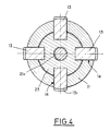
- the alignment pin 10 comprises a cage 11 of generally cylindrical shape and of diameter less than the diameter of the bores 4 of the cover 3 and of the threads 2 of the tank 1.
- This cage 11 has, at each of its ends and over part of its height, a cylindrical recess, respectively 11a and 11b, and a solid central part 11c pierced with a bore 12 in the axis of said spindle 10.
- the spindle 10 is provided with expansion means radially for centering this spindle in the tapping 2 of the fixed tank 1, constituting a reference, and for the radial movement of the cover 3 relative to the tank 1.
- These expansion means are formed, in the example shown, by four pads 13 distributed symmetrically around the axis of the cage 11 and extending over part of the height of said cage 11.
- Each shoe 13 is housed in a longitudinal opening 14 formed in said cage 11 and comprising a central part in the shape of a "U" and at each of its ends a recess 15 with a flat bottom.
- Each shoe 13 has, on its outer face and from top to bottom, two keys in projection 13a and 13b respectively, distant from each other and intended to cooperate with the bore 4 of the cover 3, an appendage 13c provided with a bearing face perpendicular to the axis of the spindle and intended to come in contact with the upper surface of the tank 1 and at its lower end, a protruding button 13d intended to cooperate with the tapping 2 of said tank 1.
- the keys 13a, 13b and 13d have an external profile, for example a curve inscribed in a circle.
- each shoe 13 has, on its inner face and at each end, an inclined ramp, respectively 16a and 16b, of the same value and in opposite directions with respect to each other.
- the pads 13 can be moved radially simultaneously by a control member designated as a whole by the reference 20 and placed in the cage 11.
- This control member 20 comprises, on the one hand, an axial operating screw 21 free only in rotation and, on the other hand, two nuts respectively 22 and 23.
- the operating screw 21 is composed of three parts ensuring distinct functions, a central part 21a passing through the bore 12 of the solid part 11c of the cage 11 and maintained on each side by a stop 24 which ensures the guiding in rotation and the maintaining in translation of said screw, and two parts respectively 21b and 21c, located at the ends, which each have a thread whose pitches are of the same value but opposite.
- the threads of the nuts 22 and 23 are also not of the same value but opposite.
- the nut 22 is screwed onto the threaded end 21b and the nut 23 is screwed onto the threaded end 21c of the operating screw 21.
- the nut 22 has, at its periphery, four inclined surfaces 22a each intended to cooperate with the inclined ramp 16a of each shoe 13.
- the nut 23 has, at its periphery, four inclined surfaces 23a intended each to cooperate with the inclined ramp 16b of each shoe 13.
- the number of inclined surfaces 22a and 23a formed at the periphery of each nut 22 and 23 corresponds to the number of pads 13.
- the screw 21 is provided at its upper end with an operating member 25 for driving said screw in rotation.
- the pads 13 are retained by two return springs 26 holding each pad 13 in contact with the nuts 22 and 23.
- the cage 11 can be tubular and include an axial stop reported for the maneuvering screw 21.
- the final positioning of the cover 3 on the tank 1 is carried out as follows.
- an alignment pin 10 is put into place in two bores 4 of the cover 3, situated at 90 ° relative to the said rods.
- Each pin 10 is introduced into the corresponding bore 5 such that the button 13d of the pads 13 enters the upper recess of the thread 2 and that the bearing face of the appendage 13c rests on the upper surface of the tank 1.
- the screw 21 is turned, by means of the operating member 25, which drives the nuts 22 and 23 in translation towards each other due to the opposite pitch of the ends 21b and 21c of said screw and threads of said nuts.
- the button 13d of the pads 13 of each spindle 10 is supported in the countersinking of the internal thread 2 of the tank 1 and the buttons 13a and 13b are supported in the bore 4 of the cover 3 (Fig. 5).
- the radial displacement of the pads 13 makes it possible to center the corresponding pin in the tapping 2 of the fixed tank 1 which constitutes a reference and simultaneously to move the cover 3 relative to the tank in order to achieve the coaxiality of the bores 4 with respect to the tapping 2 thus facilitating the subsequent screwing of the assembly members.
- the displacement of the assembly constituted by the cover and its equipment making approximately 160T is possible with very low forces by manually turning the maneuvering screws of the alignment pins thanks to a torque less than 10m.daN.
- the expansion of the alignment pins therefore makes it possible to move the cover without difficulty in the desired directions for both centering and orientation.
- each shoe 13 has, on its outer face and from top to bottom, two projecting keys, respectively 13a and 13b, distant from each other and intended to cooperate with the bore 4 of the cover 3 and an appendage 13c provided with a bearing face on the tank 1, perpendicular to the axis of the alignment pin.
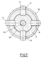
- the cage 11 is provided, at its lower part and its periphery, with keys or with an expansive ring 30 which can be moved radially and is intended to cooperate with the countersinking of the internal thread 2 of the tank 1.
- This expansive ring 30 can be moved radially by a mechanism independent of the control member 20.
- This mechanism is formed by a conical ramp 31 formed at the lower end of a jacket 32 surrounding the cage 11, this jacket being movable longitudinally parallel to the axis of the spindle.
- the shirt 32 has, at the keys 13a and 13b and the appendix 13c, openings 33 to allow the passage of these keys and this appendage.
- openings 33 are large enough to allow movement of the jacket 32 and the keys 13a and 13b as well as the appendix 13c oppose the rotation of said jacket.
- the shirt 32 is provided at its end upper part of a thread 32a into which a threaded ring 34 is screwed which bears on the cage 11.
- the threaded ring 34 is held by a stop ring 35 screwed into the cage 11.
- Each pin 10 is introduced into the corresponding bore 5 in such a way that the expansive ring 30 penetrates into the upper counterbore of the thread 2 and that the bearing face of the appendage 13c rests on the upper surface of the tank 1.
- This expansive ring 30 is supported in the recess of the thread 2 thus ensuring the centering of the corresponding pin.
Landscapes
- Engineering & Computer Science (AREA)
- Physics & Mathematics (AREA)
- Plasma & Fusion (AREA)
- General Engineering & Computer Science (AREA)
- High Energy & Nuclear Physics (AREA)
- Mechanical Engineering (AREA)
- Insertion Pins And Rivets (AREA)
- Filling Or Discharging Of Gas Storage Vessels (AREA)
- Monitoring And Testing Of Nuclear Reactors (AREA)
- Clamps And Clips (AREA)
- Furniture Connections (AREA)
- Pressure Vessels And Lids Thereof (AREA)
Claims (15)
- Ausrichtstange (10) für zwei Elemente (1, 3), die jeweils mindestens eine Öffnung (2, 4) aufweisen, die dazu gedacht ist, koaxial zur jeweils anderen angeordnet zu werden, wobei das erste Element (1) feststehend ist und das zweite Element (3) in radialer Richtung verschiebbar ist,
dadurch gekennzeichnet, daß sie aus einem Käfig (11) besteht, dessen Durchmesser kleiner ist als der Durchmesser der Öffnungen (2, 4) der beiden Elemente (1, 3), und der dazu gedacht ist, in diesen Öffnungen (2, 4) angeordnet zu werden, und daß der Käfig (11) Mittel (13) zur Ausdehnung in radialer Richtung für das Zentrieren der Stange (10) in der Öffnung (2) des ersten, festen Elements (1), das einen Bezugspunkt darstellt, und für das verschieben des zweiten Elements (3) gegenüber dem ersten Element (1) aufweist, wobei die genannten Mittel zur Ausdehnung in radialer Richtung von mindestens zwei Gleitstücken (13) gebildet werden, die symmetrisch um die Achse des Käfigs (11) angeordnet sind und jeweils in einer entsprechenden Längsöffnung 14 sitzen, die in diesem Käfig (11) ausgeführt ist, wobei diese Gleitstücke (13) durch ein Betätigungsorgan (20), das in dem genannten Käfig (11) angeordnet ist, zugleich in radialer Richtung verschiebbar sind. - Ausrichtstange nach Anspruch 1,
dadurch gekennzeichnet, daß der Käfig (11) eine allgemein zylindrische Form besitzt. - Ausrichtstange nach Anspruch 1,
dadurch gekennzeichnet, daß jede Öffnung (14) einen U-förmigen zentralen Teil und jedes ihrer Enden eine Einsenkung mit flachem Boden aufweist. - Ausrichtstange nach Anspruch 1,
dadurch gekennzeichnet, daß jedes Gleitstück (13) an seiner Außenseite und von oben nach unten zwei hervorstehende Anlageflächen (13a, 13b), die sich in Abstand voneinander befinden und dazu vorgesehen sind, mit der Öffnung (14) des zweiten, verschiebbaren Elements (3) zusammenzuwirken, sowie einen Ansatz (13c), der mit einer senkrecht zur Achse der genannten Stange (10) liegenden Fläche zur Auflage auf dem ersten, feststehenden Element (1) versehen ist, aufweist. - Ausrichtstange nach Anspruch 1,
dadurch gekennzeichnet, daß jedes Gleitstück (13) an seiner Außenseite und an seinem unteren Ende eine hervorstehende Anlagefläche (13d) aufweist, die dazu vorgesehen sind, mit der Öffnung (14) des genannten ersten, feststehenden Elements (1) zusammenzuwirken. - Ausrichtstange nach den Ansprüchen 4 und 5,
dadurch gekennzeichnet, daß die Anlageflächen (13a, 13b, 13d) ein gebogenes Außenprofil aufweisen, das in einen Kreis einbeschrieben ist. - Ausrichtstange nach Anspruch 1,
dadurch gekennzeichnet, daß jedes Gleitstück (13) an seiner Innenseite und an jedem Ende eine Abschrägung (16a, 16b) aufweist, die in entgegengesetzten Richtungen mit gleichem Wert geneigt sind. - Ausrichtstange nach einem der vorherigen Ansprüche,
dadurch gekennzeichnet, daß das Betätigungsorgan (20) einerseits eine in Achsrichtung verlaufende Betätigungsspindel (21) umfaßt, die nur drehfrei ist und einen zentralen Teil (21a) zur Führung in Drehrichtung und zum Festhalten in Vorschubrichtung in dem Käfig (11) sowie zwei Gewindeenden (21b, 21c), deren Steigungen den gleichen Wert, aber entgegengesetzte Richtungen haben, aufweist, und andererseits zwei Muttern (22, 23) umfaßt, die jeweils auf dem entsprechenden Gewindeende der Spindel (21) sitzen und dazu vorgesehen sind, die Gleitstücke (13) während der Vorschubbewegung der genannten Muttern (22, 23) durch Drehung der Betätigungsspindel (21) in radialer Richtung zu verschieben. - Ausrichtstange nach Anspruch 8,
dadurch gekennzeichnet, daß die Gewinde der Muttern (22, 23) Steigungen mit dem gleichen Wert, aber in entgegengesetzten Richtungen haben. - Ausrichtstange nach einem der vorherigen Ansprüche,
dadurch gekennzeichnet, daß jede Mutter (22, 23) an ihrem Umfang mindestens zwei ebene Flächen (22a, 23a) aufweist, die mit gleichem wert geneigt sind und dazu vorgesehen sind, jeweils mit der geneigten Abschrägung (16a, 16b) des entsprechenden Gleitstücks (13) zusammenzuwirken. - Ausrichtstange nach einem der vorherigen Ansprüche,
dadurch gekennzeichnet, daß die Gleitstücke (13) durch mindestens eine Rückstellfeder (26) festgehalten werden, die die genannten Gleitstücke (13) in Kontakt mit den Muttern (22, 23) halten - Ausrichtstange nach einem der Artsprüche 1 bis 4,
dadurch gekennzeichnet, daß der Käfig (11) an seinem unteren Ende einen Expansionsring (30) aufweist, der dazu vorgesehen ist, mit der Öffnung (2) des genannten ersten, feststehenden Elements (1) zusammenzuwirken, und in radialer Richtung durch einen Mechanismus (31) verschiebbar ist, der unabhängig von dem Betätigungsorgan (20) ist. - Ausrichtstange nach Anspruch 12,
dadurch gekennzeichnet, daß der Verschiebemechanismus des Expansionsrings (30) von einer konischen Abschrägung (31) gebildet wird, die am unteren Teil einer Ummantelung (32) ausgeführt ist, welche den Käfig der Stange umgibt, und in Längsrichtung parallel zur Achse der genannten Stange verschiebbar ist. - Ausrichtstange nach Anspruch 12,
dadurch gekennzeichnet, daß die Ummantelung (32) Öffnungen (33) für den Durchlaß der Anlageflächen der Gleitstücke (13) aufweist, wobei die genannten Anlageflächen die Drehbewegung der genannten Ummantelung (32) verhindern. - Vorrichtung zum Zentrieren eines Deckels (3) auf einem Behälter (1), insbesondere bei einem Kernreaktor, welche jeweils Öffnungen (2, 4) aufweisen, die koaxial zueinander angeordnet werden sollen,
dadurch gekennzeichnet, daß sie mindestens eine Ausrichtstange (10) nach einem der vorherigen Ansprüche umfaßt.
Applications Claiming Priority (2)
| Application Number | Priority Date | Filing Date | Title |
|---|---|---|---|
| FR9102417A FR2673447B1 (fr) | 1991-02-28 | 1991-02-28 | Broche d'alignement de deux elements et dispositif de centrage d'un couvercle sur une cuve mettant en óoeuvre ce type de broches. |
| FR9102417 | 1991-02-28 |
Publications (2)
| Publication Number | Publication Date |
|---|---|
| EP0501866A1 EP0501866A1 (de) | 1992-09-02 |
| EP0501866B1 true EP0501866B1 (de) | 1995-05-31 |
Family
ID=9410206
Family Applications (1)
| Application Number | Title | Priority Date | Filing Date |
|---|---|---|---|
| EP92400470A Expired - Lifetime EP0501866B1 (de) | 1991-02-28 | 1992-02-24 | Ausrichtstange und Zentriervorrichtung für Behälterdeckel, wobei derartige Stangen Verwendung finden |
Country Status (5)
| Country | Link |
|---|---|
| US (1) | US5263802A (de) |
| EP (1) | EP0501866B1 (de) |
| JP (1) | JPH04362303A (de) |
| DE (1) | DE69202711T2 (de) |
| FR (1) | FR2673447B1 (de) |
Families Citing this family (28)
| Publication number | Priority date | Publication date | Assignee | Title |
|---|---|---|---|---|
| JP2536098Y2 (ja) * | 1992-09-02 | 1997-05-21 | 星野楽器株式会社 | パイプの固定装置 |
| US5442973A (en) * | 1994-01-11 | 1995-08-22 | Hsin Lung Accessories Co., Ltd. | Locking mechanism between stem member and fork tube of a bicycle |
| DE9403481U1 (de) * | 1994-03-02 | 1995-06-29 | Müllenberg, Ralph, 41516 Grevenbroich | Spannanordnung mit einem Konusspannbolzen |
| US5843127A (en) * | 1994-08-22 | 1998-12-01 | Le Medical Technologies, Inc. | Fixation device and method for installing same |
| US5702215A (en) * | 1995-06-05 | 1997-12-30 | Li Medical Technologies, Inc. | Retractable fixation device |
| US5643266A (en) * | 1995-06-05 | 1997-07-01 | Li Medical Technologies, Inc. | Method and apparatus for securing ligaments |
| DE29608751U1 (de) * | 1996-05-15 | 1997-09-11 | Müllenberg, Ralph, 41516 Grevenbroich | Konusspannsatz |
| US5707395A (en) * | 1997-01-16 | 1998-01-13 | Li Medical Technologies, Inc. | Surgical fastener and method and apparatus for ligament repair |
| US5743496A (en) * | 1997-02-19 | 1998-04-28 | Upcor, Inc. | Railroad frog crossing bolt and nut assembly for clamping railroad rail sections together |
| US5902066A (en) * | 1997-07-10 | 1999-05-11 | Lake Shore Cryotronics, Inc. | Taper shaft lock |
| US6146406A (en) | 1998-02-12 | 2000-11-14 | Smith & Nephew, Inc. | Bone anchor |
| US6482210B1 (en) | 1998-11-12 | 2002-11-19 | Orthopaedic Biosystems, Ltd., Inc. | Soft tissue/ligament to bone fixation device with inserter |
| US6345929B1 (en) * | 1998-12-10 | 2002-02-12 | Svenska Expander Ab | Device for the anchorage of an axle |
| US6586957B1 (en) * | 2000-07-26 | 2003-07-01 | Micron Technology, Inc. | Non-binding alignment pin |
| US6629808B1 (en) * | 2000-10-31 | 2003-10-07 | Caterpillar Inc | Expandable mounting pin arrangement |
| AT7093U1 (de) * | 2003-12-15 | 2004-10-25 | Komperdell Sportartikel Gmbh | Klemmvorrichtung für teleskopartig ineinander geschobene rohre |
| US20050281631A1 (en) * | 2004-06-18 | 2005-12-22 | Kurt Manufacturing Company, Inc. | Pin locking system |
| US20060013648A1 (en) * | 2004-07-16 | 2006-01-19 | Kurt Manufacturing Company, Inc. | Vise stationary jaw quick locking system |
| US7648524B2 (en) * | 2005-12-23 | 2010-01-19 | Howmedica Osteonics Corp. | Porous tendon anchor |
| KR100768638B1 (ko) * | 2006-12-05 | 2007-10-18 | 손대업 | 스틱 연결구 |
| DE102007008975A1 (de) * | 2007-02-23 | 2008-09-04 | König & Meyer GmbH & Co. KG | Lautsprecherboxen-Wandhalter |
| US20110269103A1 (en) * | 2010-04-30 | 2011-11-03 | Warsaw Orthopedic, Inc. | Expandable implant |
| EP2837840B1 (de) * | 2013-08-15 | 2016-06-22 | ALSTOM Technology Ltd | Wellenkupplunganordnung und Verfahren zum Kuppeln von Wellen |
| EP2905431A1 (de) * | 2014-02-10 | 2015-08-12 | General Electric Company | Verrichtung und Verfahren von nicht invasiver Trennung von Flanschen |
| DE102015206116A1 (de) * | 2015-04-07 | 2016-10-13 | BSH Hausgeräte GmbH | Erfassung einer Lage einer Bohrung an einem Bauteil |
| CN105382745B (zh) * | 2015-12-11 | 2017-05-03 | 中国电子科技集团公司第四十一研究所 | 一种太赫兹波导法兰销钉精密装配方法及夹具 |
| US10822215B2 (en) | 2018-11-26 | 2020-11-03 | Otis Elevator Company | Fail safe bar for clutch type brake adjustment |
| CN119803285B (zh) * | 2024-12-23 | 2025-11-11 | 西安航天赛能自动化科技有限公司 | 一种分体式高精度抱销胀孔型视觉标定标靶及标定方法 |
Family Cites Families (14)
| Publication number | Priority date | Publication date | Assignee | Title |
|---|---|---|---|---|
| US1021794A (en) * | 1912-02-08 | 1912-04-02 | Henry B Newhall | Expansion-bolt anchor. |
| US2719747A (en) * | 1952-04-02 | 1955-10-04 | Mark B Layne | Expansible wedge type anchor |
| US3014399A (en) * | 1959-07-06 | 1961-12-26 | John F Schaffner | Expansion anchor bolt |
| DE1500807A1 (de) * | 1966-12-05 | 1970-05-14 | Friedrich Kittel | Zelleneckverbindungs-System |
| US3561798A (en) * | 1969-10-13 | 1971-02-09 | Allis Chalmers Mfg Co | Disconnect switch having internally clamped rotary coupling |
| DE2046519A1 (de) * | 1970-09-22 | 1972-03-23 | Equipment Gmbh & Co Kg | Parallelspannender Schalendubel |
| DE2139437B1 (de) * | 1971-08-06 | 1972-10-12 | Siemens AG, 1000 Berlin u 8000 München | Vorrichtung zum gegenseitigen Ausrichten von einander zugeordne ten Maschinenteilen |
| SE401724B (sv) * | 1973-09-29 | 1978-05-22 | Rueter Ewald | Insticksforbindning for anslutning av ror |
| US4089613A (en) * | 1977-02-09 | 1978-05-16 | Caterpillar Tractor Co. | Eccentric pin and bushing means for mounting misaligned components |
| CH629575A5 (de) * | 1977-12-20 | 1982-04-30 | Tuflex Ag | Spreizduebel. |
| SU903593A1 (ru) * | 1979-12-28 | 1982-02-07 | Предприятие П/Я М-5057 | Анкерный болт |
| DE3128610A1 (de) * | 1981-07-20 | 1983-01-27 | Hilti AG, 9494 Schaan | Spreizduebel |
| DE3514955A1 (de) * | 1985-04-25 | 1986-10-30 | Hilti Ag, Schaan | Duebel |
| DE3816523A1 (de) * | 1988-05-14 | 1989-11-23 | Manfred Schanz | Zentrierelement |
-
1991
- 1991-02-28 FR FR9102417A patent/FR2673447B1/fr not_active Expired - Fee Related
-
1992
- 1992-02-24 EP EP92400470A patent/EP0501866B1/de not_active Expired - Lifetime
- 1992-02-24 DE DE69202711T patent/DE69202711T2/de not_active Expired - Fee Related
- 1992-02-28 US US07/842,967 patent/US5263802A/en not_active Expired - Fee Related
- 1992-02-28 JP JP4043285A patent/JPH04362303A/ja active Pending
Also Published As
| Publication number | Publication date |
|---|---|
| EP0501866A1 (de) | 1992-09-02 |
| DE69202711T2 (de) | 1995-11-16 |
| FR2673447B1 (fr) | 1994-07-22 |
| US5263802A (en) | 1993-11-23 |
| DE69202711D1 (de) | 1995-07-06 |
| FR2673447A1 (fr) | 1992-09-04 |
| JPH04362303A (ja) | 1992-12-15 |
Similar Documents
| Publication | Publication Date | Title |
|---|---|---|
| EP0501866B1 (de) | Ausrichtstange und Zentriervorrichtung für Behälterdeckel, wobei derartige Stangen Verwendung finden | |
| EP1141561B1 (de) | Befestigungsvorrichtung zum schnellen an- bzw. abkoppeln eines bauteils an eine bzw. von einer auflagefläche | |
| EP0027406A1 (de) | Mit einem Kettenring versehene Rohrverbindung | |
| EP0743053B1 (de) | Sicherheits- und Kontrollvorrichtung der Verriegelung einer Radnabe, insbesondere für Rollstuhl | |
| EP0251860B1 (de) | Dichtende Verbindungsvorrichtung für zwei fixierte Rohre | |
| FR2433478A1 (fr) | Extracteur de bouchons | |
| EP0390690A1 (de) | Vorrichtung zur Montage einer schwimmend gelagerten Tonnenmutter | |
| EP0536005B1 (de) | Vorrichtung zum schnellen Montieren und Demontieren von zwei aufeinanderliegenden Teilen | |
| FR2647863A1 (fr) | Ensemble d'ecrou a verrouillage | |
| FR2728495A1 (fr) | Extracteur-decolleur | |
| BE1008013A3 (fr) | Dispositif de serrage etanche d'une colonne d'instrumentation contre une portee d'appui. | |
| EP0363267B1 (de) | Zentrier- und Befestigungsvorrichtung eines Steuerelementführungsrohrflansches auf der oberen Gitterplatte eines Kernreaktors | |
| EP0024968B1 (de) | Selbstverriegelndes Kupplungsstück und Spannwerkzeug dafür | |
| EP0373049B1 (de) | Vorrichtung zum Befestigen eines Ausrüstungsstückes auf einem Teil des Innenaufbaus eines Fahrzeuges in einer relativen Stellung zum Aussenaufbau | |
| EP0701260A1 (de) | Dichtvorrichtung für ein Innerhalb eines Adapters durch den Deckel eines Kernreaktorgefässes führendes Instrumentenführungsrohr | |
| EP0428433B1 (de) | Vorrichtung zum Fixieren der Steuerstabsführungsplatte im Kernreaktordruckgefäss | |
| EP0253707A2 (de) | Sicherungsanordnung gegen Herausschrauben für ein gleitendes Teil einer Scheibenbremse | |
| EP0373022A1 (de) | Adapter zum Fest- oder Losschranken von mit Gewinde versehenen Verbindungsmitteln | |
| FR2718276A1 (fr) | Dispositif d'étanchéité pour une colonne d'instrumentation. | |
| EP0243218A1 (de) | Positioniergerät zum Schrauben und Losschrauben einer Mutter | |
| EP0700053B1 (de) | Wiederverwendbare Verschlussvorrichtung für das obere Endstück eines Kernbrennstabbündels | |
| FR2673993A1 (fr) | Soupape de surete a membrane. | |
| FR2754101A1 (fr) | Squelette d'assemblage combustible nucleaire a tubes guides et procede de fabrication d'un tel squelette | |
| EP0365374A1 (de) | Vorrichtung zur Handhabung einer Ausdehnungsmaschine für verschraubte Verbindungselemente | |
| FR2495527A3 (fr) | Dispositif manuel de vissage et de devissage de secours d'un ecrou |
Legal Events
| Date | Code | Title | Description |
|---|---|---|---|
| PUAI | Public reference made under article 153(3) epc to a published international application that has entered the european phase |
Free format text: ORIGINAL CODE: 0009012 |
|
| AK | Designated contracting states |
Kind code of ref document: A1 Designated state(s): BE DE FR |
|
| 17P | Request for examination filed |
Effective date: 19930125 |
|
| 17Q | First examination report despatched |
Effective date: 19940711 |
|
| GRAA | (expected) grant |
Free format text: ORIGINAL CODE: 0009210 |
|
| AK | Designated contracting states |
Kind code of ref document: B1 Designated state(s): BE DE FR |
|
| REF | Corresponds to: |
Ref document number: 69202711 Country of ref document: DE Date of ref document: 19950706 |
|
| PLBE | No opposition filed within time limit |
Free format text: ORIGINAL CODE: 0009261 |
|
| STAA | Information on the status of an ep patent application or granted ep patent |
Free format text: STATUS: NO OPPOSITION FILED WITHIN TIME LIMIT |
|
| 26N | No opposition filed | ||
| PGFP | Annual fee paid to national office [announced via postgrant information from national office to epo] |
Ref country code: FR Payment date: 19990203 Year of fee payment: 8 |
|
| PGFP | Annual fee paid to national office [announced via postgrant information from national office to epo] |
Ref country code: DE Payment date: 19990204 Year of fee payment: 8 |
|
| PGFP | Annual fee paid to national office [announced via postgrant information from national office to epo] |
Ref country code: BE Payment date: 19990223 Year of fee payment: 8 |
|
| PG25 | Lapsed in a contracting state [announced via postgrant information from national office to epo] |
Ref country code: BE Free format text: LAPSE BECAUSE OF NON-PAYMENT OF DUE FEES Effective date: 20000228 |
|
| BERE | Be: lapsed |
Owner name: FRAMATOME Effective date: 20000228 |
|
| PG25 | Lapsed in a contracting state [announced via postgrant information from national office to epo] |
Ref country code: FR Free format text: LAPSE BECAUSE OF NON-PAYMENT OF DUE FEES Effective date: 20001031 |
|
| PG25 | Lapsed in a contracting state [announced via postgrant information from national office to epo] |
Ref country code: DE Free format text: LAPSE BECAUSE OF NON-PAYMENT OF DUE FEES Effective date: 20001201 |
|
| REG | Reference to a national code |
Ref country code: FR Ref legal event code: ST |