EP0501894A1 - Vorrichtung zur Entfernung von Gasblasen aus einer zirkulierenden Flüssigkeit - Google Patents
Vorrichtung zur Entfernung von Gasblasen aus einer zirkulierenden Flüssigkeit Download PDFInfo
- Publication number
- EP0501894A1 EP0501894A1 EP92420033A EP92420033A EP0501894A1 EP 0501894 A1 EP0501894 A1 EP 0501894A1 EP 92420033 A EP92420033 A EP 92420033A EP 92420033 A EP92420033 A EP 92420033A EP 0501894 A1 EP0501894 A1 EP 0501894A1
- Authority
- EP
- European Patent Office
- Prior art keywords
- liquid
- high point
- bubbles
- channeling
- channeling means
- Prior art date
- Legal status (The legal status is an assumption and is not a legal conclusion. Google has not performed a legal analysis and makes no representation as to the accuracy of the status listed.)
- Granted
Links
Images
Classifications
-
- A—HUMAN NECESSITIES
- A61—MEDICAL OR VETERINARY SCIENCE; HYGIENE
- A61M—DEVICES FOR INTRODUCING MEDIA INTO, OR ONTO, THE BODY; DEVICES FOR TRANSDUCING BODY MEDIA OR FOR TAKING MEDIA FROM THE BODY; DEVICES FOR PRODUCING OR ENDING SLEEP OR STUPOR
- A61M1/00—Suction or pumping devices for medical purposes; Devices for carrying-off, for treatment of, or for carrying-over, body-liquids; Drainage systems
- A61M1/14—Dialysis systems; Artificial kidneys; Blood oxygenators ; Reciprocating systems for treatment of body fluids, e.g. single needle systems for hemofiltration or pheresis
- A61M1/16—Dialysis systems; Artificial kidneys; Blood oxygenators ; Reciprocating systems for treatment of body fluids, e.g. single needle systems for hemofiltration or pheresis with membranes
- A61M1/1654—Dialysates therefor
- A61M1/1656—Apparatus for preparing dialysates
- A61M1/1658—Degasification
-
- B—PERFORMING OPERATIONS; TRANSPORTING
- B01—PHYSICAL OR CHEMICAL PROCESSES OR APPARATUS IN GENERAL
- B01D—SEPARATION
- B01D19/00—Degasification of liquids
Definitions
- the present invention relates to a device for removing gas bubbles from a circulating liquid, commonly called bubble trap.
- Bubble traps are used in various technical sectors as components of hydraulic circuits where the presence of gas bubbles is undesirable.
- the hydraulic circuit of the devices used in renal dialysis to manufacture and circulate a dialysis liquid in a membrane exchanger comprises several bubble traps without which the rate of transfer into the exchanger would be less, the operation of the disturbed pumps and measuring the amount of ultrafiltrating blood plasma, if any, through the distorted membrane.
- a bubble trap used in this type of device comprises, in a conventional manner, a weakly frustoconical tank closed by a cover having a bulge, at the top point of which is connected a closable purge pipe.
- the tank is separated in two over part of its height by a transverse partition, the inlet and outlet of the liquid being carried out respectively on either side of the partition.
- the function of this partition is to prevent the liquid entering the bubble trap from coming out immediately.
- the bubble trap is provided at its upper part with a liquid detector which is used to control the opening of the drain pipe whenever this detector no longer detects the presence of liquid.
- a bubble trap of this type having an internal volume of approximately 150 milliliters makes it possible to extract in one minute approximately 4.5 milliliters of air (measured at atmospheric pressure) from a liquid circulating at a rate about 1200 milliliters / minute.
- the conventional bubble trap described above has several drawbacks. Given its shape, the volume of air evacuated at each purge is relatively large, which causes a disturbance in the flow of the liquid, particularly when entering and leaving the bubble trap. In addition, this bubble trap has, compared to the tubular conduits of the circuit, a not insignificant volume, whence a start-up of the device (sterilization, initial filling, reheating) quite long. Finally, this bubble trap can never be completely drained.
- a blood reservoir constituted by a flexible banana-shaped bag having an inlet and an outlet extending in the extension of the median axis of the pocket, as well as '' a vent located at the top point of the pocket, approximately halfway between the inlet and the outlet.
- this reservoir causes the fluid flowing in its central part to slow down, it is not designed to make the eddies disappear or to favor the release of bubbles from the circulating liquid. On the other hand, emptying this tank requires manual intervention.
- An object of the present invention is to provide a bubble trap offering optimal performance while being of reduced volume, and which can be completely drained.
- a device for eliminating gas bubbles from a liquid comprising means for channeling the liquid having a curvature at a high point for gathering bubbles by gravity.
- the channeling means having a portion of increasing section upstream of the high point and a portion of decreasing section downstream of the high point, as well as means for causing a dynamic concentration of the bubbles upstream of the high point.
- the means for dynamic concentration of the bubbles comprise a portion of curved pipe situated upstream of the portion of pipe of increasing section, this portion of curved pipe having a substantially constant section and a radius of curvature less than that channeling means at the high point. It defines a curved trajectory outer for the bubbles connecting to a path of greater upper slope of the channeling means, ending at the high point.
- the device comprises collecting means for the gas constituted by an oblong cell opening onto the channeling means, at the high point.
- This arrangement makes it possible to eliminate only a small amount of gas at each purge, so that the circulation of the liquid in the channeling means is not thereby disturbed.
- the device further comprises means for causing a substantially smooth flow of the liquid in the channeling means.
- These means include a profile of the channeling means configured to match the liquid stream at the outlet of the curved section as well as, at the junction of the channeling means and the cell for collecting bubbles, a partition ensuring the continuity of the channeling means , provided with at least one slot for the passage of bubbles.
- the lower level line of the pipe means considered in the direction of the flow of the liquid, has a substantially negative or zero slope from the downstream end of the pipe portion curve.
- the bubble trap according to the invention can be emptied almost completely by gravity.
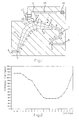
- the bubble trap of FIG. 1 comprises means for channeling the liquid to be degassed, constituted by a channel of variable section 1 having an inlet 2 and an outlet 3 arranged below the level of an intermediate settling section comprising a point top 4 for collecting bubbles by gravity.
- the inlet 2 and the outlet 3 are respectively connected to channels 5, 6 intended to be connected to pipes of a hydraulic circuit.
- Channel 1 has a curvature at the high point 4.
- the channel 1 comprises, upstream of the high point 4, a curved section 7 having its convexity facing outwards, forming means for causing the dynamic concentration of the bubbles.
- the section 7 has a radius of curvature less than that of the channel 1 at the high point 4.
- This curved section has a substantially constant section and it is connected to the settling section without breaking of continuity, the outer curve of the curved section extending by the line of greatest upper slope 8, ending at the high point 4, of the settling section. From the downstream end of the curved section 7, the section of the channel 1 gradually increases to become substantially constant on either side of the high point 4, then it decreases gradually until the outlet 3, which is located at below the level of the inlet 2 and has a section substantially equal to that of the inlet 2.
- the channel 1 is profiled to match the flow of liquid at the outlet of the curved section 7, hence in particular the slight convexity, turned towards the inside of channel 1, of the line with the highest upper slope 8, between the downstream end of the curved section 7 and the high point 4.
- the lower level line 9 of channel 1 has, from the downstream end of the curved section 7, a substantially zero slope up to the vertical point of the high point 4 then negative up to the exit 3.
- the angle made by the plus line large upper slope 10 of the terminal section of the channel 1 is chosen so that the bubbles which could be deposited on the corresponding wall can rise by gravity along this wall to the high point 4 without risking to come off or be entrained by the liquid.
- this angle is between approximately 20 ° and approximately 30 ° relative to the vertical.
- Gas collection means constituted by an oblong cell 11 with an axis substantially perpendicular to the axis of the channel 1, open on the settling section in a zone centered approximately on the high point 4 of the channel 1.
- the outlet of the cell 11 is partially blocked by a partition 12 whose lower surface extends in continuity with the upper wall of the channel 1 and which delimits two slots 13, 14 for the passage of bubbles.
- the cell 11 is equipped with purging means constituted by a pipe 15, which can be blocked by a valve 16, connecting the upper part of the cell to the atmosphere.
- the valve 16 is controlled from information supplied by a liquid detector 17 arranged to intercept the cell 11, halfway up.
- the level of the liquid in the cell 11 drops until the detector 17 no longer detects the presence of liquid.
- the valve 16 is then opened, the gas present in the cell II is purged, the liquid level rises in the cell and the valve is closed. Given the shape of the cell 11, the section of which is reduced, the quantity of gas eliminated at each purge is low and the purges frequent. The flow of liquid in the bubble trap is not disturbed.
- a bubble trap like the one shown in scale 1 in FIG. 1, with a channel 1 having a rectangular cross section and a width of 2.5 centimeters, has a volume of approximately 40 milliliters, or approximately one quarter the volume of a conventional bubble trap.
- a liquid flow rate of approximately 1200 milliliters / minute it makes it possible to extract from the liquid approximately 4.5 milliliters of gas (measured at atmospheric pressure) in one minute, that is to say the same amount of gas than a classic bubble trap.
- the present invention is not limited to the embodiment which has just been described and it is susceptible of variants.
Landscapes
- Health & Medical Sciences (AREA)
- Urology & Nephrology (AREA)
- Heart & Thoracic Surgery (AREA)
- Hematology (AREA)
- Animal Behavior & Ethology (AREA)
- Chemical Kinetics & Catalysis (AREA)
- Vascular Medicine (AREA)
- Engineering & Computer Science (AREA)
- Anesthesiology (AREA)
- Biomedical Technology (AREA)
- Chemical & Material Sciences (AREA)
- Life Sciences & Earth Sciences (AREA)
- Emergency Medicine (AREA)
- General Health & Medical Sciences (AREA)
- Public Health (AREA)
- Veterinary Medicine (AREA)
- External Artificial Organs (AREA)
- Fluid-Pressure Circuits (AREA)
- Supply Devices, Intensifiers, Converters, And Telemotors (AREA)
- Degasification And Air Bubble Elimination (AREA)
- Sampling And Sample Adjustment (AREA)
Applications Claiming Priority (2)
| Application Number | Priority Date | Filing Date | Title |
|---|---|---|---|
| FR9102692A FR2673382B1 (fr) | 1991-03-01 | 1991-03-01 | Dispositif pour eliminer les bulles de gaz d'un liquide en circulation. |
| FR9102692 | 1991-03-01 |
Publications (2)
| Publication Number | Publication Date |
|---|---|
| EP0501894A1 true EP0501894A1 (de) | 1992-09-02 |
| EP0501894B1 EP0501894B1 (de) | 1996-10-09 |
Family
ID=9410412
Family Applications (1)
| Application Number | Title | Priority Date | Filing Date |
|---|---|---|---|
| EP92420033A Expired - Lifetime EP0501894B1 (de) | 1991-03-01 | 1992-01-28 | Vorrichtung zur Entfernung von Gasblasen aus einer zirkulierenden Flüssigkeit |
Country Status (5)
| Country | Link |
|---|---|
| US (1) | US5228889A (de) |
| EP (1) | EP0501894B1 (de) |
| DE (1) | DE69214325T2 (de) |
| ES (1) | ES2094326T3 (de) |
| FR (1) | FR2673382B1 (de) |
Families Citing this family (31)
| Publication number | Priority date | Publication date | Assignee | Title |
|---|---|---|---|---|
| US5503801A (en) * | 1993-11-29 | 1996-04-02 | Cobe Laboratories, Inc. | Top flow bubble trap apparatus |
| EP0954364A4 (de) * | 1996-11-26 | 2000-04-26 | Medisystems Technology Corp | Grossblasenfallen |
| US6117342A (en) * | 1996-11-26 | 2000-09-12 | Medisystems Technology Corporation | Bubble trap with directed horizontal flow and method of using |
| DE19650406A1 (de) | 1996-12-05 | 1998-06-18 | Kevin Business Corp | Blutabsaugvorrichtung |
| DE19650407A1 (de) * | 1996-12-05 | 1998-06-10 | Kevin Business Corp | Blut-Gas-Trennverfahren und -Trennvorrichtung |
| US5983947A (en) | 1997-03-03 | 1999-11-16 | Medisystems Technology Corporation | Docking ports for medical fluid sets |
| US6051134A (en) * | 1997-03-28 | 2000-04-18 | Medisystems Technology Corporation | Bubble trap having common inlet/outlet tube |
| DE19719555A1 (de) | 1997-05-09 | 1998-11-12 | Kevin Business Corp | Verfahren und Vorrichtung zum Ausscheiden von Gas aus gashaltigem Blut |
| US6010623A (en) * | 1997-08-01 | 2000-01-04 | Medisystems Technology Corporation | Bubble trap with flat side |
| MXPA05000816A (es) | 2002-07-19 | 2005-04-28 | Baxter Int | Sistemas y metodos para realizar dialisis peritoneal. |
| ITMO20040235A1 (it) * | 2004-09-17 | 2004-12-17 | Gambro Lundia Ab | Camera snague per un circuito extraxorporeo. |
| DE102005022545B4 (de) * | 2005-05-17 | 2007-02-15 | Fresenius Medical Care Deutschland Gmbh | Verfahren zum luftfreien Füllen der Blutseite einer Hämodialysevorrichtung mit einer physiologischen Elektrolytlösung |
| GB0706908D0 (en) * | 2007-04-10 | 2007-05-16 | Nitech Solutions Ltd | Plug flow tubular mixing apparatus and method |
| US7871462B2 (en) * | 2007-10-01 | 2011-01-18 | Baxter International Inc. | Dialysis systems having air separation chambers with internal structures to enhance air removal |
| US7892331B2 (en) | 2007-10-01 | 2011-02-22 | Baxter International Inc. | Dialysis systems having air separation chambers with internal structures to enhance air removal |
| US8444587B2 (en) | 2007-10-01 | 2013-05-21 | Baxter International Inc. | Fluid and air handling in blood and dialysis circuits |
| US7892332B2 (en) * | 2007-10-01 | 2011-02-22 | Baxter International Inc. | Dialysis systems having air traps with internal structures to enhance air removal |
| US8123947B2 (en) * | 2007-10-22 | 2012-02-28 | Baxter International Inc. | Priming and air removal systems and methods for dialysis |
| US8114276B2 (en) | 2007-10-24 | 2012-02-14 | Baxter International Inc. | Personal hemodialysis system |
| US8057679B2 (en) | 2008-07-09 | 2011-11-15 | Baxter International Inc. | Dialysis system having trending and alert generation |
| IN2012DN00782A (de) * | 2009-07-03 | 2015-06-26 | Embody Ab | |
| US8382711B2 (en) | 2010-12-29 | 2013-02-26 | Baxter International Inc. | Intravenous pumping air management systems and methods |
| FR2977249B1 (fr) * | 2011-07-01 | 2014-09-26 | Serac Group | Installation de conditionnement comprenant des becs de remplissage equipes de conduits de mise en boucle du corps de bec |
| JP2013188441A (ja) * | 2012-03-15 | 2013-09-26 | Asahi Kasei Medical Co Ltd | 体外循環回路用エア抜き装置及び体外循環回路 |
| US9486590B2 (en) | 2014-09-29 | 2016-11-08 | Fenwal, Inc. | Automatic purging of air from a fluid processing system |
| WO2016104761A1 (ja) | 2014-12-25 | 2016-06-30 | アサヒカセイメディカルヨーロッパゲーエムベーハー | 溶液生成装置及び血液浄化システム |
| JP2018524718A (ja) | 2015-06-25 | 2018-08-30 | ガンブロ・ルンディア・エービーGambro Lundia Ab | 分散データベースを有する医療装置システム及び方法 |
| US10625009B2 (en) * | 2016-02-17 | 2020-04-21 | Baxter International Inc. | Airtrap, system and method for removing microbubbles from a fluid stream |
| CN110100283B (zh) | 2016-12-21 | 2023-07-04 | 甘布罗伦迪亚股份公司 | 包括具有支持外域的安全集群域的信息技术基础架构的医疗设备系统 |
| US12544498B2 (en) * | 2018-05-17 | 2026-02-10 | Gambro Lundia Ab | Treatment apparatus with gas separation device level controls and methods |
| DE102023123307A1 (de) * | 2023-08-30 | 2025-03-06 | Enmodes Gmbh | Verbindungsstück und Stoffaustauschvorrichtung mit Verbindungsstück |
Citations (5)
| Publication number | Priority date | Publication date | Assignee | Title |
|---|---|---|---|---|
| DE224106C (de) * | 1908-05-10 | 1910-07-12 | ||
| GB451905A (en) * | 1934-08-06 | 1936-08-13 | Martin Schmidt | Improvements in apparatus for separating gas and/or vapour from a mixture of gas and/or vapour and liquid flowing through a tube |
| FR1262910A (fr) * | 1959-07-22 | 1961-06-05 | Technicon Instr | Appareil pour la séparation de deux fluides |
| FR2550451A1 (en) * | 1982-08-10 | 1985-02-15 | Bentley Lab | Blood reservoir |
| US4976754A (en) * | 1989-12-05 | 1990-12-11 | Grumman Aerospace Corporation | Liquid line non-condensible gas trap |
Family Cites Families (4)
| Publication number | Priority date | Publication date | Assignee | Title |
|---|---|---|---|---|
| LU36395A1 (de) * | 1958-07-31 | |||
| US3109714A (en) * | 1959-07-22 | 1963-11-05 | Technicon Instr | Means for separating fluids from each other |
| SU553411A1 (ru) * | 1975-10-15 | 1977-04-05 | Специальное Конструкторское Бюро По Созданию Воздушных И Газовых Турбохолодильных Машин | Способ работы воздушной холодильнонагревательной установки |
| US4428757A (en) * | 1981-09-22 | 1984-01-31 | Hall Mark N | Sonic energy fluid degassing unit |
-
1991
- 1991-03-01 FR FR9102692A patent/FR2673382B1/fr not_active Expired - Lifetime
-
1992
- 1992-01-28 ES ES92420033T patent/ES2094326T3/es not_active Expired - Lifetime
- 1992-01-28 EP EP92420033A patent/EP0501894B1/de not_active Expired - Lifetime
- 1992-01-28 DE DE69214325T patent/DE69214325T2/de not_active Expired - Lifetime
- 1992-02-19 US US07/836,841 patent/US5228889A/en not_active Expired - Lifetime
Patent Citations (5)
| Publication number | Priority date | Publication date | Assignee | Title |
|---|---|---|---|---|
| DE224106C (de) * | 1908-05-10 | 1910-07-12 | ||
| GB451905A (en) * | 1934-08-06 | 1936-08-13 | Martin Schmidt | Improvements in apparatus for separating gas and/or vapour from a mixture of gas and/or vapour and liquid flowing through a tube |
| FR1262910A (fr) * | 1959-07-22 | 1961-06-05 | Technicon Instr | Appareil pour la séparation de deux fluides |
| FR2550451A1 (en) * | 1982-08-10 | 1985-02-15 | Bentley Lab | Blood reservoir |
| US4976754A (en) * | 1989-12-05 | 1990-12-11 | Grumman Aerospace Corporation | Liquid line non-condensible gas trap |
Non-Patent Citations (1)
| Title |
|---|
| SOVIET PATENTS ABSTRACTS Week 8502, 20 Février 1985 Derwent Publications Ltd., London, GB; AN 85-011079/02 & SU-A-553 411 (PETRO COLLECTION) 7 Juin 1984 * |
Also Published As
| Publication number | Publication date |
|---|---|
| FR2673382B1 (fr) | 1994-04-08 |
| DE69214325T2 (de) | 1997-04-24 |
| DE69214325D1 (de) | 1996-11-14 |
| US5228889A (en) | 1993-07-20 |
| ES2094326T3 (es) | 1997-01-16 |
| FR2673382A1 (fr) | 1992-09-04 |
| EP0501894B1 (de) | 1996-10-09 |
Similar Documents
| Publication | Publication Date | Title |
|---|---|---|
| EP0501894B1 (de) | Vorrichtung zur Entfernung von Gasblasen aus einer zirkulierenden Flüssigkeit | |
| EP0046126B1 (de) | Künstliche Niere - Regelung des Druckes der Dialyseflüssigkeit | |
| EP2683458B1 (de) | Zyklonstromabscheider | |
| EP1800725B1 (de) | Behandlungskammer für kohlenstoffen mit einer überlaufvorrichtung | |
| EP0923972A1 (de) | Selbstwaschbare Vorrichtung zur Trennung und Filtrierung von Feststoffpartikeln in einer Flüssigkeitsströmung und Verwendung in einem Kraftstoffeinspritzsystem mit einer solchen Vorrichtung | |
| EP1104742B1 (de) | Behalter fur einen Flüssigkeitkreislauf | |
| FR2604639A1 (fr) | Degazeur pour la separation de gaz ou de vapeurs, hors de courants liquide/gaz ou liquides/vapeurs dans des canalisations | |
| CH628969A5 (fr) | Generateur de vapeur comprenant un dispositif d'evacuation des contaminants du fluide de chauffe du generateur de vapeur. | |
| EP1704289A1 (de) | Flüssigkeitsevakuierungsvorrichtung und entsprechende flüssigkeitsführungsvorrichtung | |
| FR2482640A1 (fr) | Dispositif pour le prelevement de liquides dans des bassins ou similaires | |
| FR2502988A1 (fr) | Sas pour introduire de maniere dosee des corps de friction dans un systeme de canalisation pour du liquide et pour les en retirer | |
| EP0002235B1 (de) | Senkrechter Abscheider für eine Dampfflüssigkeitsmischung | |
| FR2526084A1 (fr) | Perfectionnements aux systemes d'alimentation de liquide, notamment de carburant pour moteurs d'aeronautique | |
| FR2645705A1 (fr) | Appareil d'echantillonnage d'un liquide et machine automatique de traite | |
| FR2519744A1 (fr) | Appareil de refrigeration a absorption | |
| BE527996A (de) | ||
| FR2613461A1 (fr) | Degazeur d'eau d'alimentation d'un generateur de vapeur | |
| EP0648523B1 (de) | Vorrichtung und Verfahren zum Entgasen eines Hydraulikkreislaufs | |
| EP0394100B1 (de) | Vorrichtung zum Entlüften von Flüssigkeiten und eine Anlage, die diese Vorrichtung beinhaltet | |
| FR2473459A1 (fr) | Installation de drainage sous vide des eaux usees pour bateaux | |
| BE532719A (de) | ||
| FR2542064A1 (fr) | Separateur d'eau compose de paquets de toles pour le sechage de la vapeur d'eau humide avec surchauffe consecutive de la vapeur seche | |
| BE357475A (de) | ||
| CH242376A (fr) | Distributeur. | |
| BE661573A (de) |
Legal Events
| Date | Code | Title | Description |
|---|---|---|---|
| PUAI | Public reference made under article 153(3) epc to a published international application that has entered the european phase |
Free format text: ORIGINAL CODE: 0009012 |
|
| AK | Designated contracting states |
Kind code of ref document: A1 Designated state(s): BE DE ES FR GB IT NL |
|
| 17P | Request for examination filed |
Effective date: 19921023 |
|
| 17Q | First examination report despatched |
Effective date: 19940310 |
|
| GRAG | Despatch of communication of intention to grant |
Free format text: ORIGINAL CODE: EPIDOS AGRA |
|
| GRAH | Despatch of communication of intention to grant a patent |
Free format text: ORIGINAL CODE: EPIDOS IGRA |
|
| RIN1 | Information on inventor provided before grant (corrected) |
Inventor name: CORTIAL, JEAN-LOUIS Inventor name: CHEVALLET, JACQUES |
|
| GRAH | Despatch of communication of intention to grant a patent |
Free format text: ORIGINAL CODE: EPIDOS IGRA |
|
| GRAA | (expected) grant |
Free format text: ORIGINAL CODE: 0009210 |
|
| AK | Designated contracting states |
Kind code of ref document: B1 Designated state(s): BE DE ES FR GB IT NL |
|
| REF | Corresponds to: |
Ref document number: 69214325 Country of ref document: DE Date of ref document: 19961114 |
|
| ITF | It: translation for a ep patent filed | ||
| GBT | Gb: translation of ep patent filed (gb section 77(6)(a)/1977) |
Effective date: 19961209 |
|
| REG | Reference to a national code |
Ref country code: ES Ref legal event code: FG2A Ref document number: 2094326 Country of ref document: ES Kind code of ref document: T3 |
|
| PLBE | No opposition filed within time limit |
Free format text: ORIGINAL CODE: 0009261 |
|
| 26N | No opposition filed | ||
| REG | Reference to a national code |
Ref country code: GB Ref legal event code: IF02 |
|
| PGFP | Annual fee paid to national office [announced via postgrant information from national office to epo] |
Ref country code: BE Payment date: 20021216 Year of fee payment: 12 |
|
| PGFP | Annual fee paid to national office [announced via postgrant information from national office to epo] |
Ref country code: NL Payment date: 20030131 Year of fee payment: 12 |
|
| PG25 | Lapsed in a contracting state [announced via postgrant information from national office to epo] |
Ref country code: BE Free format text: LAPSE BECAUSE OF NON-PAYMENT OF DUE FEES Effective date: 20040131 |
|
| BERE | Be: lapsed |
Owner name: *HOSPAL INDUSTRIE Effective date: 20040131 |
|
| PG25 | Lapsed in a contracting state [announced via postgrant information from national office to epo] |
Ref country code: NL Free format text: LAPSE BECAUSE OF NON-PAYMENT OF DUE FEES Effective date: 20040801 |
|
| NLV4 | Nl: lapsed or anulled due to non-payment of the annual fee |
Effective date: 20040801 |
|
| REG | Reference to a national code |
Ref country code: FR Ref legal event code: TP |
|
| REG | Reference to a national code |
Ref country code: GB Ref legal event code: 732E |
|
| REG | Reference to a national code |
Ref country code: FR Ref legal event code: GC |
|
| REG | Reference to a national code |
Ref country code: GB Ref legal event code: 732E |
|
| PGFP | Annual fee paid to national office [announced via postgrant information from national office to epo] |
Ref country code: FR Payment date: 20101221 Year of fee payment: 20 |
|
| PGFP | Annual fee paid to national office [announced via postgrant information from national office to epo] |
Ref country code: GB Payment date: 20101215 Year of fee payment: 20 |
|
| PGFP | Annual fee paid to national office [announced via postgrant information from national office to epo] |
Ref country code: DE Payment date: 20110131 Year of fee payment: 20 Ref country code: IT Payment date: 20110117 Year of fee payment: 20 |
|
| REG | Reference to a national code |
Ref country code: DE Ref legal event code: R081 Ref document number: 69214325 Country of ref document: DE Owner name: GAMBRO INDUSTRIES, FR Free format text: FORMER OWNER: GAMBRO INDUSTRIES S.A.S., MEYZIEU, FR Effective date: 20110513 |
|
| PGFP | Annual fee paid to national office [announced via postgrant information from national office to epo] |
Ref country code: ES Payment date: 20110127 Year of fee payment: 20 |
|
| REG | Reference to a national code |
Ref country code: ES Ref legal event code: PC2A Owner name: GAMBRO INDUSTRIES Effective date: 20110811 |
|
| REG | Reference to a national code |
Ref country code: DE Ref legal event code: R071 Ref document number: 69214325 Country of ref document: DE |
|
| REG | Reference to a national code |
Ref country code: DE Ref legal event code: R071 Ref document number: 69214325 Country of ref document: DE |
|
| REG | Reference to a national code |
Ref country code: GB Ref legal event code: PE20 Expiry date: 20120127 |
|
| REG | Reference to a national code |
Ref country code: FR Ref legal event code: RG Effective date: 20120215 |
|
| PG25 | Lapsed in a contracting state [announced via postgrant information from national office to epo] |
Ref country code: DE Free format text: LAPSE BECAUSE OF EXPIRATION OF PROTECTION Effective date: 20120129 |
|
| PG25 | Lapsed in a contracting state [announced via postgrant information from national office to epo] |
Ref country code: GB Free format text: LAPSE BECAUSE OF EXPIRATION OF PROTECTION Effective date: 20120127 |
|
| REG | Reference to a national code |
Ref country code: ES Ref legal event code: FD2A Effective date: 20130730 |
|
| PG25 | Lapsed in a contracting state [announced via postgrant information from national office to epo] |
Ref country code: ES Free format text: LAPSE BECAUSE OF EXPIRATION OF PROTECTION Effective date: 20120129 |