EP0502187B1 - Parallel-verarbeitungsverfahren und -vorrichtung zur algebraischen rekonstruktion einer dreidimensionalen computertomographie - Google Patents
Parallel-verarbeitungsverfahren und -vorrichtung zur algebraischen rekonstruktion einer dreidimensionalen computertomographie Download PDFInfo
- Publication number
- EP0502187B1 EP0502187B1 EP91919516A EP91919516A EP0502187B1 EP 0502187 B1 EP0502187 B1 EP 0502187B1 EP 91919516 A EP91919516 A EP 91919516A EP 91919516 A EP91919516 A EP 91919516A EP 0502187 B1 EP0502187 B1 EP 0502187B1
- Authority
- EP
- European Patent Office
- Prior art keywords
- voxel
- projection data
- data set
- subsets
- correction
- Prior art date
- Legal status (The legal status is an assumption and is not a legal conclusion. Google has not performed a legal analysis and makes no representation as to the accuracy of the status listed.)
- Expired - Lifetime
Links
Images




Classifications
-
- G—PHYSICS
- G06—COMPUTING OR CALCULATING; COUNTING
- G06T—IMAGE DATA PROCESSING OR GENERATION, IN GENERAL
- G06T12/00—Tomographic reconstruction from projections
- G06T12/20—Inverse problem, i.e. transformations from projection space into object space
-
- A—HUMAN NECESSITIES
- A61—MEDICAL OR VETERINARY SCIENCE; HYGIENE
- A61B—DIAGNOSIS; SURGERY; IDENTIFICATION
- A61B6/00—Apparatus or devices for radiation diagnosis; Apparatus or devices for radiation diagnosis combined with radiation therapy equipment
- A61B6/02—Arrangements for diagnosis sequentially in different planes; Stereoscopic radiation diagnosis
- A61B6/027—Arrangements for diagnosis sequentially in different planes; Stereoscopic radiation diagnosis characterised by the use of a particular data acquisition trajectory, e.g. helical or spiral
-
- G—PHYSICS
- G06—COMPUTING OR CALCULATING; COUNTING
- G06T—IMAGE DATA PROCESSING OR GENERATION, IN GENERAL
- G06T2211/00—Image generation
- G06T2211/40—Computed tomography
- G06T2211/424—Iterative
Definitions
- the present invention relates generally to three-dimensional (3D) computerized tomography (CT) and, more articularly, to methods and apparatus employing parallel processing for reconstructing a 3D image of an object from cone beam projection data.
- 3D three-dimensional
- CT computerized tomography
- an x-ray fan beam and a linear array detector are employed.
- Two-dimensional (2D) imaging is achieved. While the data set is complete and image quality is correspondingly high, only a single slice of an object is imaged at a time.
- a "stack of slices" approach is employed. Acquiring a 3D data set a 2D slice at a time is inherently tedious and time-consuming.
- motion artifacts occur because adjacent slices are not imaged simultaneously.
- dose utilization is less than optimal, because the distance between slices is typically less than the x-ray collimator aperture, resulting in double exposure to many parts of the body.
- a more recent approach based on what is called cone beam geometry, employs a two-dimensional array detector instead of a linear array detector, and a cone beam x-ray source instead of a fan beam x-ray source, for much faster data acquisition.
- an object is scanned, preferably over a 360° angular range, either by moving the x-ray source in a circular scanning trajectory, for example, around the object, while keeping the 2D array detector fixed with reference to the source, or by rotating the object while the source and detector remain stationary. In either case, it is relative movement between the source and object which effects scanning, compared to the conventional 2D "stack of slices" approach to achieve 3D imaging of both medical and industrial objects, with improved dose utilization.
- Literature discussing the cone beam geometry for 3D imaging and generally relevant to the subject matter of the invention includes the following: Gerald N. Minerbo, "Convolutional Reconstruction from Cone-Beam Projection Data", IEEE Trans. Nucl. Sci., Vol. NS-26, No. 2, pp. 2682-2684 (April 1979); Heang K. Tuy, "An Inversion Formula for Cone-Beam Reconstruction", SIAM J. Math., Vol. 43, No. 3, pp. 546-552 (June 1983); L.A. Feldkamp, L.C. Davis, and J.W. Kress, "Practical Cone-Beam Algorithm", J. Opt. Soc. Am.A., Vol. 1, No. 6, pp.
- the present invention is an implementation of the Algebra Reconstruction Technique (ART) for reconstructing an image of an object from its projections.
- the ART is an iterative algorithm which uses raysums to correct each voxel (volume element) of the reconstructed image at each iteration.
- the ART was initially disclosed in Richard Gordon, Robert Bender and Gabor T. Herman, "Algebraic Reconstruction Techniques (ART) for Three-dimensional Electron Microscopy and X-ray Photography", J. Theor. Biol., 29, pp. 471-481 (1970). Details regarding the mathematical foundations of the ART algorithm were described in Gabor T. Herman, Arnold Lent and Stuart W.
- the Algebra Reconstruction Technique requires a large amount of computation time, and has not been implemented with parallel processing techniques.
- the Dynamic Spatial Reconstructor employs twenty-eight x-ray sources and twenty-eight x-ray imaging systems in a synchronous scanning system to acquire data all at one time for a subsequent "stack of slices" reconstruction using conventional 2D reconstruction algorithms.
- the Robb et al. reference refers to the use of "high-speed parallel processing techniques" for the reconstruction computation.
- the invention is applicable to reconstructing an object image from cone beam projection data acquired with any scanning geometry, so long as it is well defined.
- Examples include source scanning trajectories which comprise a single circle, dual or multiple parallel circles, dual perpendicular circles, or square waves on a cylindrical surface.
- a circular source scanning trajectory lying in a plane perpendicular to a rotation axis passing through the object and perpendicular to all planes of the detector is employed.
- the discrete source positions ⁇ i are defined simply as angular positions.
- the discrete source positions ⁇ i are defined by parameters in addition to or instead of angular position.
- the 3D voxel data set V is subdivided into or organized as a plurality of m of voxel subcubes V o through V m-1 which are independent of each other. In other words, there is no overlap between adjacent voxel subcubes.
- Each voxel subcube contains a plurality of voxels. In the illustrated embodiment, boundaries between adjacent voxel subcubes lie in planes which are perpendicular to the detector planes and parallel to each other. However, independent voxel subcubes may be organized in a variety of ways.
- the 2D measured cone beam pixel data set P ⁇ i (measured projection data array) is correspondingly subdivided for each source position ⁇ i .
- the measured projection data array is divided into what may be termed projection data strips.
- the measured projection data array is divided into what may be termed projection data subsets.
- each voxel subcube has a corresponding projection data strip or projection data subset.
- the projection data strips or subsets are not independent. In other words, dependent upon the particular scanning geometry defined and the particular voxel and pixel positions for each particular source position ⁇ i , there are overlapping regions between one or more adjacent projection data strips or subsets corresponding to adjacent voxel subcubes.
- each voxel subcube and its corresponding projection data strip or subset can be processed in parallel with other pairs of voxel subcubes and corresponding projection data strips or subsets, without interference.
- a bi-level parallel-processor architecture is employed.
- Backproject/reproject processor in level 0 selectively perform voxel driven backprojection from the projection data strips or subsets to the corresponding voxel subcubes, and voxel-driven reprojection from the voxel subcubes to the corresponding projection data strips or subsets.
- Each backproject/reproject processor operates on data which is independent of the data for the other backproject/reproject processors, so the processors can operate in parallel.
- At least one split/merge processor in level 1 splits a projection data set for a particular source position ⁇ i , into projection data strips or subsets from reprojection into a projection data set.
- iterative reconstruction implementing the Algebra Reconstruction Technique for each source position ⁇ i , data are sent back and forth between level 0 for backprojection and reprojection and level 1 for splitting and merging.
- level 1 is organized in a tree-type manner as a plurality of layers.
- the split/merge processors can comprise transputers.
- a method in accordance with the invention includes the steps of organizing the voxel data set V as a plurality m of independent voxel subcubes V o through V m-1 , each voxel subcube including a plurality of voxels; initializing the voxel data set V; and performing successive iterations to correct the values of at least selected voxels of the 3D voxel data set based on the measured cone beam data sets P ⁇ i .
- boundaries between adjacent voxel subcubes lie in planes perpendicular to all planes of the 2D detector array and parallel to each other.
- the values of at least the selected voxels for each of the discrete source positions ⁇ i on the source scanning trajectory are corrected by reprojecting each voxel subcube V o through V m -1 to calculate pixel values for a corresponding 2D calculated projection data strip or subset from a group of calculated projection data strips or subsets P o i through P m -1 i of a 2D calculated projection data set P i including a plurality of pixels, the projection data strips of subsets P o i through P m -1 i overlapping in part; merging the calculated projection data strips of subsets P o i through P m -1 i to calculate pixel values of the 2D calculated projection data set P i , the step of merging including adding pixel values in any overlapping regions of the calculated projection data strips of subsets P o i through P m -1 i ; calculating a 2D correction projection data set E i including a plurality of pixels by
- the step of merging is organized in a tree-type manner as a plurality of layers and includes, for each layer, merging groups of calculated projection data strips or subsets from the next lower layer to present a lesser number of calculated projection data subsets to the next higher layer, the lowest layer merging groups of the calculated projection data strips or subsets P o i through P m -1 i from the step of reprojecting, and the highest layer producing the calculated projection data set P i .
- the step of splitting is also organized in a tree-type manner as a plurality of layers and includes, for each layer, splitting one or more correction projection data strips or subsets from the next higher layer to present a greater number of correction projection data strips or subsets to the next lower layer, the highest layer splitting the correction data set E i , and the lowest layer producing the correction projection data strips or subsets E o i through E m -1 i .
- the method further includes employing a plurality m of backproject/reproject processors corresponding to the voxel subcubes to perform the steps of reprojecting and backprojecting, and employing a plurality of split/merge processors connected in a tree structure to perform the steps of merging and splitting.
- the method additionally includes, during each iteration, for each of the discrete source positions ⁇ i , in conjunction with the steps of reprojecting each voxel subcube V o through V m-1 , calculating data values for a corresponding 2D normalizing factor data strip or subset from a group of 2D normalizing factor strips or subsets N o i through N m -1 i of a 2D normalizing factor data set N i including a plurality of pixels, the 2D normalizing factor strips or subsets N o i through N m -1 i overlapping in part; merging the normalizing factor data strips or subsets N o i through N m -1 i to calculate element values of the 2D normalizing factor data set N i ; and, during the step of calculating the 2D correction data set E i , employing the value of each corresponding element of the normalizing factor data set N i .
- the step of reprojecting is voxel driven and includes, for each voxel subcube of the plurality of voxel subcubes V o through V m-1 , initializing the corresponding calculated projection data strip or subset from the group of projection data subsets P o i through P m -1 i ; initializing the corresponding normalizing factor data strip or subset from the group of normalizing factor data strips or subsets N o i through N m -1 i ; and for each of the selected voxels of the 3D voxel data set V included in the particular voxel subcube, adding to the value of each pixel of the corresponding calculated projection data strip or subset from the group of calculated projection data strips or subsets P o i through P m -1 i influenced by the selected voxel the voxel value multiplied by a weighting factor h(p,v) determined for the voxel and pixel positions based
- the step of backprojecting is also voxel driven and includes, for each voxel subcube of the plurality of voxel subcubes V o through V m-1 , for each of the selected voxels of the 3D voxel data set V included in the particular voxel subcube, adding to the voxel value the value of each element of the corresponding 2D correction projection data strip or subset of the group of correction projection data strips or subsets E o i through E m -1 i in a pixel position influenced by the selected voxel multiplied by a weighting factor h(p,v) determined for the voxel and pixel positions based on geometry such that corrected voxel values are cumulated.
- Parallel processing apparatus implementing the Algebra Reconstruction Technique in accordance with the invention includes a data memory for storing the voxel data set V organized as a plurality m of independent voxel subcubes V o through V m-1 , each voxel subcube including a plurality of voxels; and processing elements for initializing the voxel data set V and performing successive iterations to correct the values of at least selected voxels of the 3D voxel data set based on the measured cone beam data sets P ⁇ i , during each iteration correcting the values of at least the selected voxels for each of the discrete source positions ⁇ i on the source scanning trajectory.
- the processing elements include in a level 0 a plurality m of backproject/reprojectors corresponding to the voxel subcubes, and in a level 1 at least one split/merge processor.
- the backproject/reproject processors are operable to reproject each voxel subcube V o through V m-1 to calculate pixel values for a corresponding 2D calculated projection data subset from a group of calculated projection data subsets P o i through P m -1 i of a 2D calculated projection data set P i including a plurality of pixels, the projection data subsets P o i through P m -1 i overlapping in part.
- the split/merge processor is operable to merge the calculated projection data subsets P o i through P m -1 i to calculate pixel values of the 2D calculated projection data set P i , adding pixel values in any overlapping regions of the calculated projection data subsets P o i through P m -1 i .
- the processing elements include means for calculating a 2D correction projection data set E i including a plurality of pixels determining the normalized difference between the value of each pixel of the measured projection data set pixel P ⁇ i and the value of the corresponding pixel of the calculated projection data set P i .
- the split/merge processor is also operable to split the 2D correction projection data set E i into a plurality of 2D correction projection data subsets E o i through E m -1 i corresponding to the voxel subcubes V o through V m-1 , duplicating element values for any overlapping regions of the correction projection data subsets E o i through E m -1 i .
- the backproject/reproject processors are also operable to backproject each correction projection data subset E o i through E m -1 i to correct voxel values in the corresponding voxel subcube of the plurality of voxel subcubes V o through V m-1 .
- split/merge processors are operable to merge groups of calculated projection data subsets from the next lower layer to present a lesser number of calculated projection data subsets to the next higher layer, the lowest layer merging groups of the calculated projection data subsets P o i through P m -1 i from the backproject/reproject processors, and the highest layer producing the calculated projection data set P i .
- the split/merge processors are also operable to split one or more correction projection data subsets from the next higher layer to present a greater number of correction projection data subsets to the next lower layer, the highest layer splitting the correction data set E i , and the lowest layer producing the correction projection data subsets E o i through E m -1 i .
- At least the split/merge processors comprise transputers.
- the split/merge processors of each layer each include on I/O connected to the next higher layer, and three I/O parts connected to the next lower layer.
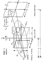
- a cube 20 alternatively represents an actual 3D object being scanned or a 3D voxel (volume element) data set V representing the actual object.
- the voxel data set V may be indexed, for example, by voxel number v. It will be appreciated that, during a scanning and data acquisition operation, the actual object is scanned with x-rays; and, during a subsequent image reconstruction operation, the voxel data set V is calculated to represent an image of the actual object.
- the present invention is directed to image reconstruction.
- a global coordinate system C 3 v ( X v , f v , Z v ) is defined, with its origin (0,0,0) at the center of the voxel data set V or object 20.
- the object 20 is positioned within a field of view between a cone beam x-ray point source 22 and a 2D array detector 24, from which cone beam projection data is acquired.
- the 2D array detector 24 is connected to a conventional high speed data acquisition system (not shown).
- An axis of rotation 26 coincident with the Z v axis passes through the field of view and the object 20. Perpendicular to the Z v axis of rotation 26 is a midplane within which the X v and Y v axes lie, as well as a circular source scanning trajectory 28 centered on the Z v axis of rotation 26.
- the x-ray source 22 moves relative to the object 20 along the source scanning trajectory 28, while the 2D array detector 24 remains fixed in position relative to the source 22.
- the source 22 and detector 24 may be rotated around a stationary object 20, or the object 20 may be rotated while the source 22 and detector 24 remain stationary.
- Each measured cone beam pixel data set P ⁇ i includes a plurality of pixels indexed, for example, by pixel number p.
- data are acquired at a number of angular positions or view angles ⁇ i around the object.
- ⁇ is the source-to-detector distance and ⁇ is the source-to-rotation-axis distance.
- the x-ray source 22 is located at [ ⁇ sin ⁇ i ,- ⁇ cos ⁇ i ,0] T and a 2D projection P ⁇ i is acquired.
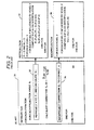
- FIG. 2 summarizes the procedure of the prior art three-dimensional Algebra Reconstruction Technique (ART), which is an iterative procedure using raysums to correct the value of each voxel of the 3D voxel data set V at each iteration. After a number of iterations, the values of the voxel data set V converge to represent the actual 3D object.
- ART three-dimensional Algebra Reconstruction Technique
- the procedure commences by initializing the 3D voxel data set V, for example by clearing all voxel values to zero.
- the procedure then goes through successive iterations and, for each iteration, through each source position or projection angle ⁇ i corresponding to discrete angular positions on the source scanning trajectory 28.
- the procedure is completed (not shown) either when a predetermined number of iterations have been processed, or when the error is below a predetermined threshold.
- the projection angles ⁇ i may be processed in any order, either sequentially or in some other order depending upon the particular scanning geometry, the order of projection angle ⁇ i processing can affect the rate of convergence of the voxel data set V.
- Box 32 states the step of reprojection, which is in turn detailed in Box 34 in the manner of a subroutine.
- the 3D voxel data set V (or a selected portion of interest) is reprojected from real space to projection space to generate a 2D calculated projection data set P i for the particular projection angle ⁇ i .
- the 2D calculated projection data set P i corresponds on a pixel-by-pixel basis with the actual measured cone beam pixel data set P ⁇ i , but with actual pixel data values differing depending upon how accurately the voxel data set V represents the actual object, and depending upon various inherent computational errors.
- a 2D normalizing factor data set N i is also calculated, corresponding on a pixel-by-pixel basis with the calculated and measured projection data sets P i and P ⁇ i .
- the calculated projection data set P i and the normalizing factor data set N i are each initialized by clearing all pixels to zero. Then for each voxel v of the 3D voxel data set V, each pixel p of the calculated projection data set P i and the corresponding normalizing factor data set N i influenced by the voxel is identified in a manner described hereinbelow with reference again to FIG. 1. For each pixel p so influenced by voxel v, the following three operations are performed: (1) A weighting factor h(p,v) for the particular voxel and pixel positions is determined based on geometry, for example by a well-known bi-linear interpolation process.
- a 2D correction projection data set E i indexed, for example, by pixel number p is calculated. For each pixel of the corresponding data sets, the difference between the value of the measured projection data set pixel P ⁇ i (p) and the value of the corresponding calculated projection data set pixel P i (p) is determined, and then normalized by dividing by the value of the corresponding normalizing factor data set element N i (p) . The result is the value of the corresponding correction projection data set element E i (p) .
- Box 36 states the step of backprojection, which is in turn detailed in Box 38 in the manner of a subroutine.
- the 2D correction projection data set E i for the particular projection angle ⁇ i is backprojected from projection space to real space to correct voxel values in the 3D voxel data set V.
- each pixel p of the correction projection data set E i influenced by the voxel is identified.
- the weighting factor h(p,v) is determined via interpolation based on geometry, and then the value of the correction projection data set pixel E i (p) is multiplied by the weighting factor h(p,v), and the product added to the value of the voxel value V(v), such that voxel values are cumulatively corrected.
- V ( x v , y v , z v ) represent a three-dimensional voxel data set defined in the three-dimensional discrete Cartesian coordinate system, C 3 v , with the origin located at the center of the 3D cubic data.
- C 3 v three-dimensional discrete Cartesian coordinate system
- every voxel can be indexed by ( i x , i y , i z ).
- each voxel is stated as where K x , K y , and K z denote the voxel resolution along the x, y, and z axis in the coordinate system C 3 v , respectively.
- a two-dimensional discrete Cartesian coordinate system C 2 P ⁇ i is used to address each detector element in the 2D area detector. Every detector element D(x d , y d ) is indexed by the ⁇ x and ⁇ y are used to indicate the detector resolution along the x and y axis, respectively.
- the relative relationship between C 2 P ⁇ i and C 3 V can be stated as 4x4 transformation function T P ⁇ i ⁇ v .
- the coordinate (x d , y d ) can be transferred to the voxel coordinate system C 3 V by applying the transformation function T P ⁇ i ⁇ v , i.e., transformation function T P ⁇ i ⁇ v , which transfers the detector coordinate system to the voxel coordinate system, is expressed as rotating about the y axis by ⁇ i , then rotating 90° around the reference x axis, and finally translating by O p ; i.e., where ⁇ i is View angle measured respect to the y axis in C 3 V
- a voxel-driven approach is applied for both backprojection and reprojection.
- a unique intersection point (x d , y d ) on the detector plane C 2 P ⁇ i can be calculated for a given voxel ( x v , y v , z v ) in C 3 v , as represented in FIG. 1 by the intersection point 40 and voxel 42 along line 44.
- weighting factors reflecting the contribution of each voxel to each pixel on the detector plane can be calculated for reprojection, and weighting factors reflecting the contribution of each pixel on the detector plane to each voxel can be calculated for backprojection.
- the 3D voxel data set V (or 20 in FIG. 1) is organized as a plurality m of independent voxel subcubes V o through V m-1 .
- the voxel subcubes are independent in the sense that no overlapping region exists between adjacent voxel subcubes. While the voxel data set may be divided in a variety of ways, preferably boundaries between adjacent voxel subcubes lie in planes which are perpendicular to the detector planes and parallel to each other, as depicted in FIG. 3.
- the size of each voxel subcube is constrained by the memory space associated with each processor element used to do back projection and reprojection, described hereinbelow with reference to FIGS. 5, 8 and 9.
- FIG. 4 depicts the geometric relationship between the voxel subcubes of FIG. 3 and projections on the detector array for each angular position ⁇ i .
- the projection subsets take the form of parallel strips on the detector plane.
- each voxel subcube and its corresponding projection strip can be projected and reprojected in parallel with other pairs of voxel subcubes and projection strips without interference.
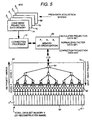
- FIG. 5 depicts apparatus in accordance with the invention, comprising a bi-level parallel processor architecture. Included in the FIG. 5 apparatus is a data memory 60 for storing the 3D voxel data set V, organized as indicated into separate memory areas for each of the independent voxel subcubes V o through V m-1 .
- a level 0 In a level 0 are a plurality of m of backproject/reproject processors, such as processor 62, corresponding respectively to the voxel subcubes.
- Each of the backproject/reproject processors of level 0 operates independently of and in parallel with the other processors of level 0 to reproject and backproject back and forth between a particular voxel subcube and a particular projection strip as part of the overall iterative process.
- a level 1 is at least one, and preferably many, split/merge processor, such as processor 64.
- processors in level 1 are organized in layers in a tree-type manner. Each level 1 processor (or node) has three sons and one parent in the particular embodiment illustrated.
- the INMOS T800 transputer is basically a computer on a chip with a 32-bit integer processor and a 64 bit floating point processor, with a practically achievable floating point computation rate of approximately 1.5 MFLOPS. It includes 4 kBytes of on-chip memory, and address space for 4 Gbytes of off-chip memory.
- Each transputer can be connected to four neighbors over a point-to-point link with a 20-Mbit/second bandwidth.
- An available development system namely a Meiko Computing Surface, includes 512 transputers, with a maximum computation rate of approximately 800 MFLOPS.
- the level 1 processors are operable, following a level 0 reproject operation, which produces m calculated projection data subsets P o i through P m -1 i , to merge the calculated projection data subsets P o i through P m -1 i into a memory 66, as well as to merge normalizing factor data subsets N o i through N m -1 i from the level 0 processors into a single normalizing factor data set N i for storing in the memory 66.
- the level 1 processors are also operable to split a correction projection data set E i stored in the memory 66 into a plurality of correction projection data subsets E o i through E m -1 i for backprojection by the level 0 processors.
- the arrows 68 and 70 respectively indicate these two types of operation, namely, reproject then merge, and split then backproject.
- a correction processor 72 which operates in a conventional manner as described hereinabove to calculate the correction projection data set E i based on the difference between the calculated projection data set P i , and the measured projection data set P ⁇ i for the particular projection angle ⁇ i .
- the measured projection data sets P ⁇ i resulting from data acquisition as described hereinabove with reference to FIG. 1 are stored in exemplary memories 74, 76, 78 and 80.
- each split/merge processor reads in a projection reads in a projection strip from its parent node, splits it into three projection substrips, and then distributes those to its son nodes for further splitting or backprojection.
- each split/merge processor reads in three projection strips from its son nodes (either the backproject/reproject processors or split/merger processors), merges them into one projection strip, and sends that projection strip to its parent node for further merging.
- the number of processor layers in level 1 is related to the total number of backproject/reproject processors in level 0.
- each split/merge processor reads in a projection strip from its parent node and splits it into three projection substrips, and then distributes those to its son nodes.
- Each backproject/reproject processor receives a projection strip from its parent node and performs voxel-driven backprojection.
- each backproject/reproject processor calculates a projection strip for the desired view angle and sends the resulting projection strip to its parent node (split/merge processor) for merging.
- the 3D algebra Reconstruction Technique is achieved by iteratively performing backprojection and reprojection.
- the entire parallel processing procedure of the 3D cone beam algebra reconstruction algorithm can be divided into four major tasks: split, merge, backproject, and reproject.
- the reproject process is executed by each backproject/reproject processor in level 0 or reprojection. Its primary function is to generate a projection strip for a given view angle from a voxel subcube and send the results to its parent node for projection merging.
- the reprojection procedure uses a voxel-driven approach and is illustrated as follows:
- the merge process runs on the split/merge processors in level 1 for reprojection purposes. Its primary function is to merge three projection strips, read from its three son nodes, into one. As mentioned hereinabove, an overlapping region between two projection strips corresponds to two adjacent voxel subcubes. The merge is achieved by adding projection strips together in the overlapping region according to its global coordinate system, as represented in FIG. 8.
- the split process is executed by the split/merge processors in level 1 for backprojection. Its primary function is to partition the projection strip into three projection substrips according to the global location of the voxel subcubes processed by its son nodes. As mentioned hereinabove, an overlapping region exists between projection strips that corresponds to two adjacent voxel subcubes. Projection data in the overlapping region are duplicated in two adjacent projection strips, as represented in FIG. 9.
- the processor reads in projection strips from its parent node and reads in information from its son nodes about the starting point and dimensions of the voxel sector of its son nodes. Then the input projection strip is divided into three projection substrips, according to the global location of the voxel subcubes processed by its son nodes and the scanning geometry, and the resulting three projection strips are distributed to its son nodes.
- the backproject process is executed by the backproject/reproject processors in level 0 for backprojection. Its primary function is to read in a projection strip for every view angle and backproject it to a voxel subcube.
- the backprojection procedure uses a voxel-driven approach and is illustrated as follows:
- an voxel data set can be divided into (M) voxel subcubes, each with voxels.
- the variable m is used to denote the voxel subcube index.
- For each voxel subcube its corresponding region on the projection plane that may contribute to it can be identified according to the scanning geometry.
- the starting point of the projection strip corresponding to the m th voxel subcube is stated as and each projection strip contains projection elements.
- the variable N P x denotes the number of detector elements along the x axis of the projection coordinate system.
- the geometric relationship between the starting point of each voxel subcube and the starting point of its corresponding projection strip is illustrated in FIG. 4.
- Each voxel in a voxel subcube handled by a backproject/reproject processor is indexed by (i v ,j v ,k v ), where Its global coordinate can be calculated as
- the voxel resolutions along the x, y, and z axes are specified as ( R x V , R y V , R z V ).
- This integrating line will intersect the detector plane at the location (X d ,Y d ) in the projection coordinate system show in FIG. 4.
- Y d ⁇ V Z V Y cos ⁇ i - V X sin ⁇ i + ⁇
- the bi-level tree-type parallel-proessor architecture and the four major processing tasks are implemented on the Meiko Computing Surface (T800 transputer development system).
- Each backproject/reproject processor of each split/merge processor (FIG. 5) is mapped to a T800 transputer.
- each FIG. 5 split/merge processor in level 1 has one parent node and three son nodes, which facilitates implementation with transputers which have four I/O parts. However, different numbers of son nodes may be employed.
- level 1 may comprise a single processor which merges all projection strips or subsets in a single operation, or correspondingly splits the complete projection data set into a plurality of projection strips or subsets in one operation.
- This technique can be applied to both medical and industrial 3D CT imaging. Because it is based on a voxel-driven algebraic reconstruction technique, it is particularly useful for reconstructing regions of interest.
- the parallelism provided by the Split and Merge Reconstruction method can be extended to large data sets. Performance improves as the number of backproject/reproject processors grows.
Landscapes
- Physics & Mathematics (AREA)
- General Physics & Mathematics (AREA)
- Engineering & Computer Science (AREA)
- Theoretical Computer Science (AREA)
- Apparatus For Radiation Diagnosis (AREA)
- Image Generation (AREA)
- Image Processing (AREA)
- Image Analysis (AREA)
Claims (15)
- Parallelverarbeitungsverfahren auf der Basis der Algebra-Rekonstruktions-Technik (ART) zum iterativen Rekonstruieren aus Kegelbündel-Projektionsdaten eines 3D Voxeldatensatzes V, der ein Bild von einem Objekt darstellt, wobei die Kegelbündel-Projektionsdaten durch Verwendung einer Kegelbündel-Röntgenquelle und eines zweidimensionalen Arraydetektors gewonnen werden, um das Objekt entlang einer Quellenabtastbahn abzutasten, um an jedem von mehreren diskreten Quellenorten θi auf der Quellenabtastbahn einen gemessenen 2D Kegelbündel-Pixeldatensatz Pi zu erhalten, wobei das Verfahren gekennzeichnet ist durch:a. Organisieren des Voxeldatensatzes V als eine Anzahl von m unabhängigen Voxelunterwürfeln V0 bis Vm-1, wobei jeder Voxelunterwürfel mehrere Voxel aufweist,b. Initialisieren des Voxeldatensatzes V undc. Ausführen aufeinanderfolgender Iterationen, um Werte von wenigstens gewählten Voxeln des 3D Voxeldatensatzes auf der Basis der gemessenen Kegelbündel-Datensätze P̂i zu korrigieren, wobei während jeder Iteration die Werte von wenigstens den gewählten Voxeln für jeden der diskreten Quellenorte θi auf der Quellenabtastbahn korrigiert werden, indemc.1. jeder Voxelunterwürfel VO bis Vm-1 reprojiziert wird, um Pixelwerte für entsprechende berechnete 2D Projektionsdaten-Untersätze Pi o bis Pi m-1 zu berechnen, die mehrere Pixel enthalten, wobei sich die Projektionsdaten-Untersätze Pi o bis Pi m-1 teilweise überlappen,c.2. Mischen der berechneten Projektionsdaten-Untersätze Pi o bis Pi m-1, um Pixelwerte von einem berechneten 2D Projektionsdatensatz Pi zu berechnen, wobei der Mischschritt enthält, daß Pixelwerte in allen überlappenden Bereichen der berechneten Projektionsdaten-Untersätze Pi o bis Pi m-1 addiert werden,c.3. Berechnen eines 2D Korrekturprojektions-Datensatzes Ei, der mehrere Pixel enthält, indem die normierte Differenz zwischen dem Wert von jedem Pixel des gemessenen Projektionsdatensatzes P̂i und dem Wert des entsprechenden Pixels des berechneten Projektionsdatensatzes Pi ermittelt wird,c.4. Teilen des 2D Korrekturprojektions-Datensatzes Ei in mehrere 2D Korrekturprojektions-Datenuntersätze Ei o bis Ei m-1, die den Voxelunterwürfeln V0 bis Vm-1 entsprechen, wobei sich die 2D Korrekturprojektions-Datenuntersätze Ei o bis Ei m-1 teilweise überlappen, und der Schritt des Teilens enthält, daß Elementenwerte für alle überlappenden Bereiche der Korrekturprojektions-Datensätze Ei o bis Ei m-1 dupliziert werden, undc.5. jeder Korrekturprojektions-Datensatz Ei o bis Ei m-1 rückprojiziert wird, um Voxelwerte in dem entsprechenden Voxelunterwürfel der Anzahl von Voxelunterwürfeln V0 bis Vm-1 zu korrigieren.
- Verfahren nach Anspruch 1, wobei der Schritt c.2. des Mischens in einer baumartigen Weise als eine Anzahl von Schichten organisiert wird und für jede Schicht enthält, daß Gruppen von berechneten Projektionsdaten-Untersätzen aus der nächst tieferen Schicht gemischt werden, um eine kleinere Anzahl von berechneten Projektionsdaten-Untersätzen für die nächst höhere Schicht darzustellen, wobei die unterste Schicht Gruppen von den berechneten Projektionsdaten-Untersätzen Pi o bis Pi m-1 aus dem Reprojektionsschritt c.1. mischt und die höchste Schicht den berechneten Projektionsdatensatz Pi erzeugt, und
der Schritt c.4. des Teilens in einer baumartigen Weise als eine Anzahl von Schichten organisiert wird und für jede Schicht enthält, daß einer oder mehrere KorrekturProjektions-Datenuntersätze aus der nächst höchsten Schicht geteilt wird, um eine größere Anzahl von Korrekturprojektions-Datenuntersätze für die nächst tiefere Schicht darzustellen, wobei die höchste Schicht den Korrekturdatensatz Ei teilt und die tiefste Schicht die Korrekturprojektions-Datenuntersätze Ei o bis Ei m-1 erzeugt. - Verfahren nach Anspruch 1 oder 2, das eine Anzahl von m Rückprojizier/Reprojizier-Prozessoren verwendet, die den Voxelunterwürfeln entsprechen, um die Schritte c.1. und c.5. des Reprojizierens und Rückprojizierens ausführen.
- Verfahren nach einem der Ansprüche 1 bis 3, das die Verwendung von mehreren Teil/Misch-Prozessoren enthält, die in einer Baumstruktur verbunden sind, um die Schritte c.2. und c.4. des Mischens und Teilens auszuführen.
- Verfahren nach einem der Ansprüche 1 bis 4, enthaltend während jeder Iteration für jeden der diskreten Quellenorte θi:in Verbindung mit jedem Schritt c.1. des Reprojizierens von jedem Voxel-Unterwürfel V0 bis Vm-1, Berechnen von Datenwerten für einen entsprechenden Normierungsfaktor-Datenuntersatz aus einer Gruppe von 2D Normierungsfaktor-Untersätzen Ni o bis Ni m-1 von einem 2D Normierungsfaktor-Datensatz Ni, der eine Anzahl von Pixeln enthält, wobei sich die 2D Normierungsfaktor-Untersätze Ni o bis Ni m-1 teilweise überlappen,Mischen der Normierungsfaktor-Datenuntersätze Ni o bis Ni m-1, um Elementwerte in dem 2D Normierungsfaktor-Datensatz Ni zu berechnen, undwährend des Berechnungsschrittes des 2D Korrekturdatensatzes Ei, Verwenden jedes entsprechenden Elementes des Normierungsfaktor-Datensatzes Ni zum Normieren der Differenz zwischen dem Wert von jedem Pixel des gemessenen Projektionsdatensatzes P̂i und dem Wert der entsprechenden Pixel des berechneten Projektionsdatensatzes Pi.
- Verfahren nach einem der Ansprüche 1 bis 4, wobei der Schritt c.1. des Reprojizierens Voxel-getrieben ist und für jeden Voxel-Unterwürfel der Anzahl von Voxel-Unterwürfeln V0 bis Vm-1 enthält:Initialisieren des entsprechenden berechneten Projektionsdaten-Untersatzes aus der Gruppe von Projektionsdaten-Untersätzen Pi o bis Pi m-1 undfür jeden der gewählten Voxel des 3D Voxeldatensatzes V, der in dem jeweiligen Voxel-Unterwürfel enthalten ist, Addieren des Wertes von jedem Pixel des entsprechenden berechneten Projektionsdaten-Untersatzes aus der Gruppe von berechneten Projektionsdaten-Untersätze Pi o bis Pi m-1, die durch das gewählte Voxel beeinflußt sind, wobei die Voxelwerte mit einem Gewichtungsfaktor h(p,v) multipliziert werden, der für das geometrisch entsprechende Voxel und die Voxelpositionen ermittelt ist, so daß die Pixelwerte in dem entsprechenden künstlichen Projektionsdaten-Untersatz kummuliert werden.
- Verfahren nach Anspruch 5, wobei der Schritt c.1. des Reprojizierens Voxel-getrieben ist und für jeden Voxel-Unterwürfel der Anzahl von Voxel-Unterwürfeln V0 bis Vm-1 enthält:Initialisieren des entsprechenden berechneten Projektionsdaten-Untersatzes aus der Gruppe von Projektionsdaten-Untersätzen Pi o bis Pi m-1,Initialisieren des entsprechenden Normierungsfaktor-Datenuntersatzes aus der Gruppe von Normierungsfaktor-Datenuntersätzen Ni o bis Ni m-1für jedes der gewählten Voxel des 3D Voxeldatensatzes V, der in dem jeweiligen Voxel-Unterwürfel enthalten ist, Addieren des Wertes von jedem Pixel des entsprechenden berechneten Projektionsdaten-Untersatzes aus der Gruppe von berechneten Projektionsdaten-Untersätzen Pi o bis Pi m-1, die durch das gewählte Voxel beeinflußt sind, wobei die Voxelwerte mit einem Gewichtungsfaktor h(p,v) multipliziert werden, der für das geometrisch entsprechende Voxel und die Pixelpositionen ermittelt wird, so daß die Pixelwerte in dem entsprechenden künstlichen Projektionsdaten-Untersatz kummuliert werden, undAddieren zu dem Wert von jedem Pixel des entsprechenden Normierungsfaktor-Datenuntersatzes aus der Gruppe von Normierungsfaktor-Datenuntersätzen Ni o bis Ni m-1 des Quadrates des Gewichtungsfaktors h(p,v), der für die geometrisch entsprechenden Voxel- und Pixelpositionen ermittelt ist, so daß Elementwerte in dem entsprechenden Normierungsfaktor-Datenuntersatz kummuliert werden.
- Verfahren nach einem der Ansprüche 1 bis 7, wobei der Schritt c.5. des Rückprojizierens Voxel-getrieben ist und für jeden Voxel-Unterwürfel der Anzahl von Voxel-Unterwürfeln V0 bis Vm-1 für jeden der gewählten Voxel des 3D Voxeldatensatzes V, der in den jeweiligen Voxel-Unterwürfel enthalten ist, enthält:
Addieren zu dem Voxelwert den Wert von jedem Element des entsprechenden 2D Korrekturprojektions-Datenuntersatzes von der Gruppe von Korrekturprojektions-Datenuntersätze Ei o bis Ei m-1 in einer Pixelposition, die durch das gewählte Voxel beeinflußt wird, multipliziert mit einem Gewichtungsfaktor h(p,v), der für die geometrisch entsprechenden Voxel- und Pixelpositionen ermittelt wird, so daß korrigierte Voxelwerte kummuliert werden. - Verfahren nach Anspruch 6, wobei der Schritt c.5. Voxel-getrieben ist und für jeden Voxel-Unterwürfel der Anzahl von Voxel-Unterwürfeln V0 bis Vm-1, wobei jeder der gewählten Voxel des 3D Voxeldatensatzes V in dem jeweiligen Voxel-Unterwürfel enthalten ist, enthält:
Addieren zu dem Voxelwert den Wert von jedem Element des entsprechenden 2D Korrekturprojektions-Datenuntersatzes der Gruppe von Korrekturprojektions-Datenuntersätze Ei o bis Ei m-1 in einer Pixelposition, die durch das gewählte Voxel beeinflußt ist, multipliziert mit dem Gewichtungsfaktor h(p,v), der für die geometrisch entsprechenden Voxel- und Pixelpositionen ermittelt wird, so daß korrigierte Voxelwerte kummuliert werden. - Verfahren nach einem der vorstehenden Ansprüche, wobei Grenzlinien zwischen benachbarten Voxel-Unterwürfeln in Ebenen liegen, die senkrecht zu allen Ebenen des Detektors und parallel zueinander sind.
- Verfahren nach einem der vorstehenden Ansprüche, wobei die berechneten Projektionsdaten-Untersätze Projektionsdatenbänder sind, die Korrekturprojektions-Datenuntersätze Projektionsdatenbänder sind und die Normierungsfaktor-Datenuntersätze Bänder sind.
- Parallelverarbeitungseinrichtung, die die Algebra-Rekonstruktions-Technik (ART) implementiert zum iterativen Rekonstruieren aus Kegelbündel-Projektionsdaten eines 3D Voxeldatensatzes V, der ein Bild von einem Objekt darstellt, wobei die Kegelbündel-Projektionsdaten gewonnen werden durch Verwendung einer Kegelbündel-Röntgenquelle und eines zweidimensionalen Array-Detektors, um das Objekt entlang einer Quellenabtastbahn abzutasten bzw. zu scannen, um an jeder einer Anzahl diskreter Quellenorten θi auf der Quellenabtastbahn einen gemessenen 2D Kegelbündel-Pixeldatensatz P̂i zu erhalten, wobei die Einrichtung gekennzeichnet ist durch:einen Datenspeicher (60) zum Speichern der Voxeldaten V, die als eine Anzahl m von unabhängigen Voxel-Unterwürfeln V0 bis Vm-1 organisiert sind, wobei jeder Voxel-Unterwürfel eine Anzahl von Voxeln enthält,Verarbeitungselemente (68, 70, 72) zum Initialisieren des Voxeldatensatzes V und Ausführen aufeinanderfolgender Iterationen, um die Werte von wenigstens gewählten Voxeln des 3D Voxeldatensatzes zu korrigieren auf der Basis der gemessenen Kegelbündel-Datensätze P̂i während jeder Iteration, wobei die Werte von wenigstens den gewählten Voxeln für jede der diskreten Winkelpositionen θi auf der Quellenabtastbahn korrigiert werden, wobei die Verarbeitungselemente in einer Stufe 0 eine Anzahl m von Rückprojizier/Reprojizier-Prozessoren (62) entsprechend den Voxel-Unterwürfeln und in einer Stufe 1 wenigstens einen Teil/Misch-Prozessor (64) enthalten,wobei die Rückprojizier/Reprojizier-Prozessoren (62) die Funktion haben, jeden Voxel-Unterwürfel V0 bis Vm-1 zu reprojizieren, um Pixelwerte für entsprechende berechnete 2D Projektions-Untersätze Pi o bis Pi m-1 zu berechnen, die eine Anzahl von Pixeln enthalten, wobei sich die Projektionsdaten-Untersätze Pi o bis Pi m-1 teilweise überlappen,wobei der wenigstens eine Teil/Misch-Prozessor (64) die Funktion hat, die berechneten Projektionsdaten-Untersätze Pi o bis Pi m-1 zu mischen, um Pixelwerte von einem berechneten 2D Projektionsdaten-Untersatz Pi zu berechnen, wobei Pixelwerte in allen überlappenden Bereichen der berechneten Projektionsdaten-Untersätze Pi o bis Pi m-1 addiert werden,wobei die Verarbeitungselemente (68, 70, 72) Mittel (72) enthalten zum Berechnen eines 2D Korrekturprojektions-Datensatzes E1, indem die normierte Differenz zwischen dem Wert von jedem Pixel des gemessenen Projektionsdatensatzes P̂i und dem Wert des entsprechenden Pixels des berechneten Projektionsdatensatzes Pi ermittelt wird,wobei der wenigstens eine Teil/Misch-Prozessor (64) die Funktion hat, den 2D Korrekturprojektions-Datensatz E1 in eine Anzahl von 2D Korrekturprojektions-Datenuntersätze Ei o bis Ei m-1 entsprechend den Voxel-Unterwürfeln V0 bis Vm-1 zu teilen, wobei sich die 2D Korrekturprojektions-Datenuntersätze teilweise überlappen und Elementwerte von allen überlappenden Bereichen der Korrekturprojektions-Untersätze dupliziert werden, unddie Rückprojizier/Reprojizier-Prozessoren (62) die Funktion haben, jeden Korrekturprojektions-Datenuntersatz Ei o bis Ei m-1 rückzuprojizieren, um Voxelwerte in dem entsprechenden Voxelunterwürfel der Anzahl von Voxel-Unterwürfeln V0 bis Vm-1 zu korrigieren.
- Einrichtung nach Anspruch 12, wobei eine Anzahl von Teil/Misch-Prozessoren (64, 62) vorgesehen ist, die als eine baumartige Struktur in mehreren Schichten organisiert sind,wobei die Teil/Misch-Prozessoren die Funktion haben, Gruppen von berechneten Projektionsdaten-Untersätzen aus der nächst unteren Schicht zu mischen, um eine kleinere Anzahl von berechneten Projektionsdaten-Untersätzen für die nächst höhere Schicht darzustellen, wobei die unterste Schicht Gruppen der berechneten Projektionsdaten-Untersätze Pi o bis Pi m-1 aus den Rückprojizier/Reprojizier-Prozessoren mischt und die höchste Schicht den berechneten Projektionsdatensatz Pi erzeugt, unddie Teil/Misch-Prozessoren die Funktion haben, einen oder mehrere Korrekturprojektions-Datenuntersätze aus der nächst höheren Schicht zu teilen, um eine größere Anzahl von Korrekturprojektions-Datenuntersätze für die nächst tiefere Schicht darzustellen, wobei die höchste Schicht den Korrekturdatensatz Ei teilt und die tiefste Schicht die Korrekturprojektions-Datenuntersätze Ei o bis Ei m-1 erzeugt.
- Einrichtung nach Anspruch 12 oder 13, wobei wenigstens die Teil/Misch-Prozessoren Transputer aufweisen.
- Einrichtung nach einem der Ansprüche 12 bis 14, wobei die Teil/Misch-Prozessoren von jeder Schicht einen I/O-Port, der mit der nächst höheren Schicht verbunden ist, und drei I/O-Ports aufweist, die mit der nächst tieferen Schicht verbunden sind.
Applications Claiming Priority (3)
| Application Number | Priority Date | Filing Date | Title |
|---|---|---|---|
| US07/586,163 US5253171A (en) | 1990-09-21 | 1990-09-21 | Parallel processing method and apparatus based on the algebra reconstruction technique for reconstructing a three-dimensional computerized tomography (CT) image from cone beam projection data |
| PCT/US1991/006822 WO1992005507A1 (en) | 1990-09-21 | 1991-09-19 | Parallel processing method and apparatus based on the algebra reconstruction technique for reconstructing a three-dimensional computerized tomography |
| US586163 | 1996-01-11 |
Publications (2)
| Publication Number | Publication Date |
|---|---|
| EP0502187A1 EP0502187A1 (de) | 1992-09-09 |
| EP0502187B1 true EP0502187B1 (de) | 1997-12-03 |
Family
ID=24344563
Family Applications (1)
| Application Number | Title | Priority Date | Filing Date |
|---|---|---|---|
| EP91919516A Expired - Lifetime EP0502187B1 (de) | 1990-09-21 | 1991-09-19 | Parallel-verarbeitungsverfahren und -vorrichtung zur algebraischen rekonstruktion einer dreidimensionalen computertomographie |
Country Status (6)
| Country | Link |
|---|---|
| US (1) | US5253171A (de) |
| EP (1) | EP0502187B1 (de) |
| JP (1) | JPH0731740B2 (de) |
| CA (1) | CA2042225A1 (de) |
| DE (1) | DE69128341T2 (de) |
| WO (1) | WO1992005507A1 (de) |
Cited By (12)
| Publication number | Priority date | Publication date | Assignee | Title |
|---|---|---|---|---|
| WO2005036466A1 (en) | 2003-10-14 | 2005-04-21 | Philips Intellectual Property & Standards Gmbh | Iterative data reconstruction |
| US7609884B1 (en) | 2004-12-23 | 2009-10-27 | Pme Ip Australia Pty Ltd | Mutual information based registration of 3D-image volumes on GPU using novel accelerated methods of histogram computation |
| US7623732B1 (en) | 2005-04-26 | 2009-11-24 | Mercury Computer Systems, Inc. | Method and apparatus for digital image filtering with discrete filter kernels using graphics hardware |
| US7693318B1 (en) | 2004-01-12 | 2010-04-06 | Pme Ip Australia Pty Ltd | Method and apparatus for reconstruction of 3D image volumes from projection images |
| US7778392B1 (en) | 2004-11-02 | 2010-08-17 | Pme Ip Australia Pty Ltd | Method of reconstructing computed tomography (CT) volumes suitable for execution on commodity central processing units (CPUs) and graphics processors, and apparatus operating in accord with those methods (rotational X-ray on GPUs) |
| US8189002B1 (en) | 2004-10-29 | 2012-05-29 | PME IP Australia Pty, Ltd. | Method and apparatus for visualizing three-dimensional and higher-dimensional image data sets |
| US8775510B2 (en) | 2007-08-27 | 2014-07-08 | Pme Ip Australia Pty Ltd | Fast file server methods and system |
| US8976190B1 (en) | 2013-03-15 | 2015-03-10 | Pme Ip Australia Pty Ltd | Method and system for rule based display of sets of images |
| US9019287B2 (en) | 2007-11-23 | 2015-04-28 | Pme Ip Australia Pty Ltd | Client-server visualization system with hybrid data processing |
| US9355616B2 (en) | 2007-11-23 | 2016-05-31 | PME IP Pty Ltd | Multi-user multi-GPU render server apparatus and methods |
| US9454813B2 (en) | 2007-11-23 | 2016-09-27 | PME IP Pty Ltd | Image segmentation assignment of a volume by comparing and correlating slice histograms with an anatomic atlas of average histograms |
| US9509802B1 (en) | 2013-03-15 | 2016-11-29 | PME IP Pty Ltd | Method and system FPOR transferring data to improve responsiveness when sending large data sets |
Families Citing this family (72)
| Publication number | Priority date | Publication date | Assignee | Title |
|---|---|---|---|---|
| US5457321A (en) * | 1990-02-20 | 1995-10-10 | Kabushiki Kaisha Toshiba | Spect apparatus utilizing fan-parallel data conversion |
| US5333164A (en) * | 1991-12-11 | 1994-07-26 | General Electric Company | Method and apparatus for acquiring and processing only a necessary volume of radon data consistent with the overall shape of the object for efficient three dimensional image reconstruction |
| JP3382941B2 (ja) * | 1992-04-01 | 2003-03-04 | ソニー株式会社 | 放射線診断装置 |
| US5469486A (en) * | 1992-08-07 | 1995-11-21 | General Electric Company | Projection domain reconstruction method for helical scanning computed tomography apparatus with multi-column detector array employing overlapping beams |
| US5412703A (en) * | 1993-02-04 | 1995-05-02 | Institute For Radiological Image Science, Inc. | Reduced partial volume artifacts in image reconstruction, with application to X-ray computed tomography |
| US6219441B1 (en) * | 1993-06-22 | 2001-04-17 | General Electric Company | Reconstruction of images from three-dimensional cone beam data |
| WO1995009395A1 (en) * | 1993-09-27 | 1995-04-06 | Oracle Corporation | Method and apparatus for parallel processing in a database system |
| US5500883A (en) * | 1994-12-05 | 1996-03-19 | General Electric Company | Method and system for efficiently generating radon derivative data in a cone beam computerized tomography implementation |
| US5513236A (en) * | 1995-01-23 | 1996-04-30 | General Electric Company | Image reconstruction for a CT system implementing a dual fan beam helical scan |
| US5594766A (en) * | 1995-03-31 | 1997-01-14 | General Electric Company | Method and apparatus for improving efficiency in computing radon derivatives for CT imaging |
| US5541970A (en) * | 1995-05-09 | 1996-07-30 | General Electric Company | Image reconstruction for a CT system implementing a four fan beam helical scan |
| US5588033A (en) * | 1995-06-06 | 1996-12-24 | St. Jude Children's Research Hospital | Method and apparatus for three dimensional image reconstruction from multiple stereotactic or isocentric backprojections |
| US5559846A (en) * | 1995-09-22 | 1996-09-24 | General Electric Company | Technique for improving processor efficiency in CT imaging |
| US5546439A (en) * | 1995-11-02 | 1996-08-13 | General Electric Company | Systems, methods and apparatus for incrementally reconstructing overlapped images in a CT system implementing a helical scan |
| AU726047B2 (en) * | 1995-11-15 | 2000-10-26 | Gen-Probe Incorporated | Nucleic acid probes complementary to human papillomavirus nucleic acid and related methods and kits |
| US5559847A (en) * | 1995-12-06 | 1996-09-24 | General Electric Company | Systems, methods and apparatus for reconstructing images in a CT system implementing a helical scan |
| US5606585A (en) * | 1995-12-21 | 1997-02-25 | General Electric Company | Methods and apparatus for multislice helical image reconstruction in a computer tomography system |
| JP3373720B2 (ja) * | 1996-03-25 | 2003-02-04 | 株式会社日立メディコ | X線断層撮影装置 |
| US5841890A (en) * | 1996-05-06 | 1998-11-24 | Northrop Grumman Corporation | Multi-dimensional wavelet tomography |
| US5663995A (en) * | 1996-06-06 | 1997-09-02 | General Electric Company | Systems and methods for reconstructing an image in a CT system performing a cone beam helical scan |
| SE9602594D0 (sv) * | 1996-07-01 | 1996-07-01 | Stefan Nilsson | Förfarande och anordning vid datortomografi |
| US6510435B2 (en) * | 1996-09-02 | 2003-01-21 | Rudolf Bayer | Database system and method of organizing an n-dimensional data set |
| US5805098A (en) * | 1996-11-01 | 1998-09-08 | The United States Of America As Represented By The Secretary Of The Army | Method and system for forming image by backprojection |
| US6038282A (en) * | 1997-04-30 | 2000-03-14 | Siemens Aktiengesellschaft | X-ray imaging system |
| US5907594A (en) * | 1997-07-01 | 1999-05-25 | Analogic Corporation | Reconstruction of volumetric images by successive approximation in cone-beam computed tomography systems |
| US5909476A (en) * | 1997-09-22 | 1999-06-01 | University Of Iowa Research Foundation | Iterative process for reconstructing cone-beam tomographic images |
| US6236709B1 (en) | 1998-05-04 | 2001-05-22 | Ensco, Inc. | Continuous high speed tomographic imaging system and method |
| US6351548B1 (en) * | 1999-06-23 | 2002-02-26 | The Board Of Trustees Of The University Of Illinois | Fast hierarchical reprojection algorithm for tomography |
| US6263096B1 (en) * | 1999-06-23 | 2001-07-17 | The Board Of Trustees Of The University Of Illinois | Multilevel domain decomposition method for fast reprojection of images |
| DE10008053A1 (de) | 2000-02-22 | 2001-09-06 | Siemens Ag | Röntgeneinrichtung und medizinischer Arbeitsplatz für die Diagnostik und für chirurgische Eingriffe im Kopf - und Kiefernbereich eines Patienten |
| US6477221B1 (en) * | 2001-02-16 | 2002-11-05 | University Of Rochester | System and method for fast parallel cone-beam reconstruction using one or more microprocessors |
| EP2362346B1 (de) * | 2001-04-18 | 2013-07-10 | Landmark Graphics Corporation | Verfahren und Computerprogrammprodukt zur Volumendarstellung |
| US20050114831A1 (en) * | 2001-04-18 | 2005-05-26 | Andres Callegari | Volume body renderer |
| DE10304662A1 (de) * | 2003-02-05 | 2004-08-19 | Siemens Ag | Verfahren zur Erzeugung von Bildern in der Computertomographie mit einem 3D-Bildrekonstruktionsverfahren |
| EP1623383A1 (de) * | 2003-05-06 | 2006-02-08 | Philips Intellectual Property & Standards GmbH | Iteratives verfahren zur bestimmung der räumlichen verteilung von eigenschaftswerten |
| JP4222930B2 (ja) * | 2003-12-10 | 2009-02-12 | ジーイー・メディカル・システムズ・グローバル・テクノロジー・カンパニー・エルエルシー | 3次元逆投影方法および装置並びにx線ct装置 |
| EP1577837A1 (de) * | 2004-03-17 | 2005-09-21 | Deutsches Krebsforschungszentrum Stiftung des öffentlichen Rechts | 3D-Kegelstrahlrekonstruktion |
| US20060072800A1 (en) * | 2004-09-24 | 2006-04-06 | General Electric Company | Method and system for distributed iterative image reconstruction |
| US7251306B2 (en) * | 2004-11-17 | 2007-07-31 | General Electric Company | Methods, apparatus, and software to facilitate iterative reconstruction of images |
| FR2887058B1 (fr) * | 2005-06-10 | 2007-08-31 | Daniel Ackerman | Procede et dispositif de reconstruction 3d d'un objet a partir de plusieurs images 2d |
| US7498581B2 (en) * | 2005-10-05 | 2009-03-03 | Koninklijke Philips Electronics N.V. | Distributed iterative image reconstruction |
| DE102005051620A1 (de) * | 2005-10-27 | 2007-05-03 | Siemens Ag | Verfahren zur Rekonstruktion einer tomographischen Darstellung eines Objektes |
| DE602006021771D1 (de) * | 2005-11-01 | 2011-06-16 | Koninkl Philips Electronics Nv | Verfahren und system zur pet-bildrekonstruktion unter verwendung von teilen von ereignisdaten |
| EP2011085A1 (de) * | 2006-04-25 | 2009-01-07 | Wisconsin Alumni Research Foundation | System und verfahren zur schätzung fehlender daten von ct-bildgebungsprojektionen |
| US7738729B2 (en) * | 2006-08-02 | 2010-06-15 | Morpho Detection, Inc. | Systems and methods for reducing an artifact within an image |
| WO2008025771A1 (de) * | 2006-08-30 | 2008-03-06 | Fraunhofer-Gesellschaft Zur Foerderung Der Angewandten Forschung E.V. | Optimierte erfassung und verarbeitung von bilddaten eines objekts in einer einrichtung zur erzeugung computertomographischer bilder |
| US7853061B2 (en) * | 2007-04-26 | 2010-12-14 | General Electric Company | System and method to improve visibility of an object in an imaged subject |
| US8019151B2 (en) * | 2007-06-11 | 2011-09-13 | Visualization Sciences Group, Inc. | Methods and apparatus for image compression and decompression using graphics processing unit (GPU) |
| US9904969B1 (en) | 2007-11-23 | 2018-02-27 | PME IP Pty Ltd | Multi-user multi-GPU render server apparatus and methods |
| US10311541B2 (en) | 2007-11-23 | 2019-06-04 | PME IP Pty Ltd | Multi-user multi-GPU render server apparatus and methods |
| JP4665019B2 (ja) * | 2008-08-18 | 2011-04-06 | 株式会社東芝 | X線コンピュータ断層撮影装置 |
| US20100207942A1 (en) * | 2009-01-28 | 2010-08-19 | Eigen, Inc. | Apparatus for 3-d free hand reconstruction |
| AU2010246365B2 (en) * | 2009-11-27 | 2014-04-24 | Ge Sensing & Inspection Technologies Gmbh | Computed tomography method, computer software, computing device and computed tomography system for determining a volumetric representation of a sample |
| US8798227B2 (en) * | 2010-10-15 | 2014-08-05 | Kabushiki Kaisha Toshiba | Medical image processing apparatus and X-ray computed tomography apparatus |
| US10878544B2 (en) * | 2011-11-03 | 2020-12-29 | Koninklijke Philips N.V. | Image data processing |
| US8948337B2 (en) * | 2013-03-11 | 2015-02-03 | General Electric Company | Computed tomography image reconstruction |
| US11183292B2 (en) | 2013-03-15 | 2021-11-23 | PME IP Pty Ltd | Method and system for rule-based anonymized display and data export |
| US11244495B2 (en) | 2013-03-15 | 2022-02-08 | PME IP Pty Ltd | Method and system for rule based display of sets of images using image content derived parameters |
| US10070839B2 (en) | 2013-03-15 | 2018-09-11 | PME IP Pty Ltd | Apparatus and system for rule based visualization of digital breast tomosynthesis and other volumetric images |
| US10540803B2 (en) | 2013-03-15 | 2020-01-21 | PME IP Pty Ltd | Method and system for rule-based display of sets of images |
| TWI517093B (zh) | 2013-10-11 | 2016-01-11 | 國立陽明大學 | Computer tomography reconstruction method |
| EP3164677A4 (de) | 2014-07-03 | 2018-06-06 | Phase Sensitive Innovations, Inc. | Phasengesteuerter hochfrequenzempfänger |
| CN104408756B (zh) * | 2014-10-30 | 2017-05-31 | 东软集团股份有限公司 | 一种pet图像重建方法及装置 |
| US10019818B2 (en) * | 2015-03-12 | 2018-07-10 | Toshiba Medical Systems Corporation | Concurrent forward- and back-projection iterative reconstruction system |
| US11599672B2 (en) | 2015-07-31 | 2023-03-07 | PME IP Pty Ltd | Method and apparatus for anonymized display and data export |
| US9984478B2 (en) | 2015-07-28 | 2018-05-29 | PME IP Pty Ltd | Apparatus and method for visualizing digital breast tomosynthesis and other volumetric images |
| US10897309B2 (en) | 2015-08-03 | 2021-01-19 | Phase Sensitive Innovations, Inc. | Distributed array for direction and frequency finding |
| WO2017024074A1 (en) | 2015-08-03 | 2017-02-09 | Phase Sensitive Innovations, Inc. | Distributed array for direction and frequency finding |
| US10313012B2 (en) | 2015-08-03 | 2019-06-04 | Phase Sensitive Innovations, Inc. | Distributed array for direction and frequency finding |
| US10909679B2 (en) | 2017-09-24 | 2021-02-02 | PME IP Pty Ltd | Method and system for rule based display of sets of images using image content derived parameters |
| CN111812130A (zh) * | 2020-07-15 | 2020-10-23 | 深圳市金园智能科技有限公司 | 一种基于x射线的材料内部3d成像方法及装置 |
| CN114384541B (zh) * | 2021-12-15 | 2026-01-23 | 武汉万集光电技术有限公司 | 点云目标检测方法、终端设备及计算机可读存储介质 |
Family Cites Families (2)
| Publication number | Priority date | Publication date | Assignee | Title |
|---|---|---|---|---|
| JPH02503840A (ja) * | 1988-04-13 | 1990-11-08 | アナロジック・コーポレーション | バック投射装置と方法 |
| US5023895A (en) * | 1989-03-02 | 1991-06-11 | Innovative Imaging Systems, Inc. | Three dimensional tomographic system |
-
1990
- 1990-09-21 US US07/586,163 patent/US5253171A/en not_active Expired - Fee Related
-
1991
- 1991-05-09 CA CA002042225A patent/CA2042225A1/en not_active Abandoned
- 1991-09-19 WO PCT/US1991/006822 patent/WO1992005507A1/en not_active Ceased
- 1991-09-19 JP JP3517552A patent/JPH0731740B2/ja not_active Expired - Fee Related
- 1991-09-19 DE DE69128341T patent/DE69128341T2/de not_active Expired - Fee Related
- 1991-09-19 EP EP91919516A patent/EP0502187B1/de not_active Expired - Lifetime
Cited By (17)
| Publication number | Priority date | Publication date | Assignee | Title |
|---|---|---|---|---|
| US7430269B2 (en) | 2003-10-14 | 2008-09-30 | Koninklijke Philips Electronics N.V. | Iterative data reconstruction |
| WO2005036466A1 (en) | 2003-10-14 | 2005-04-21 | Philips Intellectual Property & Standards Gmbh | Iterative data reconstruction |
| US7693318B1 (en) | 2004-01-12 | 2010-04-06 | Pme Ip Australia Pty Ltd | Method and apparatus for reconstruction of 3D image volumes from projection images |
| US8189002B1 (en) | 2004-10-29 | 2012-05-29 | PME IP Australia Pty, Ltd. | Method and apparatus for visualizing three-dimensional and higher-dimensional image data sets |
| US7778392B1 (en) | 2004-11-02 | 2010-08-17 | Pme Ip Australia Pty Ltd | Method of reconstructing computed tomography (CT) volumes suitable for execution on commodity central processing units (CPUs) and graphics processors, and apparatus operating in accord with those methods (rotational X-ray on GPUs) |
| US7609884B1 (en) | 2004-12-23 | 2009-10-27 | Pme Ip Australia Pty Ltd | Mutual information based registration of 3D-image volumes on GPU using novel accelerated methods of histogram computation |
| US7623732B1 (en) | 2005-04-26 | 2009-11-24 | Mercury Computer Systems, Inc. | Method and apparatus for digital image filtering with discrete filter kernels using graphics hardware |
| US9167027B2 (en) | 2007-08-27 | 2015-10-20 | PME IP Pty Ltd | Fast file server methods and systems |
| US8775510B2 (en) | 2007-08-27 | 2014-07-08 | Pme Ip Australia Pty Ltd | Fast file server methods and system |
| US9531789B2 (en) | 2007-08-27 | 2016-12-27 | PME IP Pty Ltd | Fast file server methods and systems |
| US9454813B2 (en) | 2007-11-23 | 2016-09-27 | PME IP Pty Ltd | Image segmentation assignment of a volume by comparing and correlating slice histograms with an anatomic atlas of average histograms |
| US9355616B2 (en) | 2007-11-23 | 2016-05-31 | PME IP Pty Ltd | Multi-user multi-GPU render server apparatus and methods |
| US9019287B2 (en) | 2007-11-23 | 2015-04-28 | Pme Ip Australia Pty Ltd | Client-server visualization system with hybrid data processing |
| US9595242B1 (en) | 2007-11-23 | 2017-03-14 | PME IP Pty Ltd | Client-server visualization system with hybrid data processing |
| US9509802B1 (en) | 2013-03-15 | 2016-11-29 | PME IP Pty Ltd | Method and system FPOR transferring data to improve responsiveness when sending large data sets |
| US9524577B1 (en) | 2013-03-15 | 2016-12-20 | PME IP Pty Ltd | Method and system for rule based display of sets of images |
| US8976190B1 (en) | 2013-03-15 | 2015-03-10 | Pme Ip Australia Pty Ltd | Method and system for rule based display of sets of images |
Also Published As
| Publication number | Publication date |
|---|---|
| EP0502187A1 (de) | 1992-09-09 |
| CA2042225A1 (en) | 1992-03-22 |
| DE69128341T2 (de) | 1998-06-25 |
| US5253171A (en) | 1993-10-12 |
| DE69128341D1 (de) | 1998-01-15 |
| WO1992005507A1 (en) | 1992-04-02 |
| JPH0731740B2 (ja) | 1995-04-10 |
| JPH05501326A (ja) | 1993-03-11 |
Similar Documents
| Publication | Publication Date | Title |
|---|---|---|
| EP0502187B1 (de) | Parallel-verarbeitungsverfahren und -vorrichtung zur algebraischen rekonstruktion einer dreidimensionalen computertomographie | |
| US5257183A (en) | Method and apparatus for converting cone beam X-ray projection data to planar integral and reconstructing a three-dimensional computerized tomography (CT) image of an object | |
| US6078638A (en) | Pixel grouping for filtering cone beam detector data during 3D image reconstruction | |
| EP1478274B1 (de) | Verfahren und geräte für schnelle fächerstrahl-tomographie | |
| US6201849B1 (en) | Apparatus and method for reconstruction of volumetric images in a helical scanning cone-beam computed tomography system | |
| US5907594A (en) | Reconstruction of volumetric images by successive approximation in cone-beam computed tomography systems | |
| KR20040040440A (ko) | 나선형 컴퓨터 단층촬영용 최적 fbp 알고리즘 | |
| WO2004019279A2 (en) | Apparatus and method for reconstruction of volumetric images in a divergent scanning computed tomography system | |
| US20050047542A1 (en) | Image reconstruction method for divergent beam scanner | |
| CA2056528A1 (en) | Parallel processing method and apparatus for reconstructing a three-dimensional computerized tomography (ct) image of an object from cone beam projection data or from planar integrals | |
| US5341460A (en) | Method and apparatus for producing a three-dimensional computerized tomography image of an object with improved conversion of cone beam data to radon data | |
| WO2004034908A1 (ja) | X線断層撮影装置 | |
| EP1800264A1 (de) | Bildwiederherstellung mit voxelabhängiger interpolation | |
| US7272205B2 (en) | Methods, apparatus, and software to facilitate computing the elements of a forward projection matrix | |
| US10089758B1 (en) | Volume image reconstruction using projection decomposition | |
| US8379948B2 (en) | Methods and systems for fast iterative reconstruction using separable system models | |
| Valton et al. | Analysis of cone‐beam artifacts in off‐centered circular CT for four reconstruction methods | |
| CN120635243B (zh) | 基于神经辐射场的螺旋ct图像重建方法 | |
| US20060029180A1 (en) | Exact filtered back projection (FBP) algorithm for spiral computer tomography with variable pitch | |
| JP2006513812A (ja) | 可変ピッチ・スパイラルct用の効率的な画像復元アルゴリズム | |
| CN114708344B (zh) | 一种基于场论的ct图像局部重建的系统及方法 | |
| Ziegler et al. | Iterative reconstruction of a region of interest for transmission tomography | |
| Tam | Exact image reconstruction in cone beam 3D CT | |
| Li et al. | Reconstruction algorithms | |
| WO2005107598A1 (en) | Efficient circle and line cone beam computed tomography |
Legal Events
| Date | Code | Title | Description |
|---|---|---|---|
| PUAI | Public reference made under article 153(3) epc to a published international application that has entered the european phase |
Free format text: ORIGINAL CODE: 0009012 |
|
| 17P | Request for examination filed |
Effective date: 19920403 |
|
| AK | Designated contracting states |
Kind code of ref document: A1 Designated state(s): DE FR GB NL |
|
| 17Q | First examination report despatched |
Effective date: 19951222 |
|
| GRAG | Despatch of communication of intention to grant |
Free format text: ORIGINAL CODE: EPIDOS AGRA |
|
| GRAH | Despatch of communication of intention to grant a patent |
Free format text: ORIGINAL CODE: EPIDOS IGRA |
|
| GRAH | Despatch of communication of intention to grant a patent |
Free format text: ORIGINAL CODE: EPIDOS IGRA |
|
| GRAA | (expected) grant |
Free format text: ORIGINAL CODE: 0009210 |
|
| AK | Designated contracting states |
Kind code of ref document: B1 Designated state(s): DE FR GB NL |
|
| PG25 | Lapsed in a contracting state [announced via postgrant information from national office to epo] |
Ref country code: NL Free format text: LAPSE BECAUSE OF FAILURE TO SUBMIT A TRANSLATION OF THE DESCRIPTION OR TO PAY THE FEE WITHIN THE PRESCRIBED TIME-LIMIT Effective date: 19971203 Ref country code: FR Free format text: LAPSE BECAUSE OF FAILURE TO SUBMIT A TRANSLATION OF THE DESCRIPTION OR TO PAY THE FEE WITHIN THE PRESCRIBED TIME-LIMIT Effective date: 19971203 |
|
| REF | Corresponds to: |
Ref document number: 69128341 Country of ref document: DE Date of ref document: 19980115 |
|
| EN | Fr: translation not filed | ||
| NLV1 | Nl: lapsed or annulled due to failure to fulfill the requirements of art. 29p and 29m of the patents act | ||
| PG25 | Lapsed in a contracting state [announced via postgrant information from national office to epo] |
Ref country code: GB Free format text: LAPSE BECAUSE OF NON-PAYMENT OF DUE FEES Effective date: 19980919 |
|
| PLBE | No opposition filed within time limit |
Free format text: ORIGINAL CODE: 0009261 |
|
| STAA | Information on the status of an ep patent application or granted ep patent |
Free format text: STATUS: NO OPPOSITION FILED WITHIN TIME LIMIT |
|
| 26N | No opposition filed | ||
| GBPC | Gb: european patent ceased through non-payment of renewal fee |
Effective date: 19980919 |
|
| PGFP | Annual fee paid to national office [announced via postgrant information from national office to epo] |
Ref country code: DE Payment date: 20031031 Year of fee payment: 13 |
|
| PG25 | Lapsed in a contracting state [announced via postgrant information from national office to epo] |
Ref country code: DE Free format text: LAPSE BECAUSE OF NON-PAYMENT OF DUE FEES Effective date: 20050401 |