EP0502256A2 - Dispositif de barbotage à gaz pour le traitement de l'acier en poche - Google Patents
Dispositif de barbotage à gaz pour le traitement de l'acier en poche Download PDFInfo
- Publication number
- EP0502256A2 EP0502256A2 EP91121834A EP91121834A EP0502256A2 EP 0502256 A2 EP0502256 A2 EP 0502256A2 EP 91121834 A EP91121834 A EP 91121834A EP 91121834 A EP91121834 A EP 91121834A EP 0502256 A2 EP0502256 A2 EP 0502256A2
- Authority
- EP
- European Patent Office
- Prior art keywords
- connecting pin
- flushing device
- supply pipe
- connecting sleeve
- gas supply
- Prior art date
- Legal status (The legal status is an assumption and is not a legal conclusion. Google has not performed a legal analysis and makes no representation as to the accuracy of the status listed.)
- Withdrawn
Links
Images


Classifications
-
- B—PERFORMING OPERATIONS; TRANSPORTING
- B22—CASTING; POWDER METALLURGY
- B22D—CASTING OF METALS; CASTING OF OTHER SUBSTANCES BY THE SAME PROCESSES OR DEVICES
- B22D1/00—Treatment of fused masses in the ladle or the supply runners before casting
- B22D1/002—Treatment with gases
- B22D1/005—Injection assemblies therefor
Definitions
- the invention relates to a purging device for steel treatment pans with a ceramic body having gas passage openings, which can be connected to a supply line for purging gas.
- flushing units consist of a ceramic perforated brick (receiving stone), in the conical opening of which a ceramic flushing cone (flushing insert) is inserted.
- These purge cones are usually provided with a sheet metal casing which has a connecting pipe through which purge gas is introduced under pressure.
- the flushing cone namely the so-called joint flushing cone and the so-called pore flushing cone.
- the flushing gas is conducted into a joint which is formed between the outer surface of the ceramic cone and the sheet metal jacket.
- the sheet metal casing has a dual function in the joint flushing cone, namely directing the gas jet and fastening and holding the flushing cone in the perforated stones of the steel treatment pan.
- the sheet metal sheathing is firmly around the ceramic cone.
- the purging gas is passed through the stone.
- the sheet metal sheathing is only required for the pore flushing cone to seal the stone against the connecting pipe.
- the sheet metal casing is also considered indispensable for holding and fastening the flushing cone.
- the invention has for its object to provide a flushing device in which the disadvantages mentioned in the prior art are avoided.
- a connecting pin is formed on the bottom of the ceramic body, with which a connecting sleeve having a gas supply pipe can be coupled in a gas-tight and detachable manner.
- the present invention is based on the omission of the sheet metal casing which was previously considered indispensable, i.e. an uncontrollable joint between the flushing cone and the perforated brick is avoided and thus overcomes the disadvantages resulting from the sheet metal-coated flushing cone in the prior art.
- the danger of a pan breakthrough as a result of the sheet metal sheathing in the area of the flushing cone is eliminated.
- the connecting sleeve engages around the connecting pin and that a sealing plate having the gas supply pipe can be screwed to the connecting sleeve, in order to be moved for sealing against the underside of the connecting pin.
- a radially outwardly extending flange is formed on the outer surface of the connecting sleeve encompassing the connecting pin parallel to the underside of the connecting pin, this flange being provided with a large number of threaded bores with the aid of which the sealing plate can be screwed to the connecting sleeve is.
- This embodiment is particularly easy to handle, since first only the connecting sleeve is applied to the connecting pin and then a sealing plate is screwed onto the connecting sleeve.
- the process of sealing is therefore divided into two parts and makes it possible to use higher forces and thereby achieve an excellent sealing performance.
- the connecting sleeve is designed as a union screw sleeve encompassing the connecting pin, which is penetrated by the gas supply pipe, the union screw sleeve encompassing a sealing plate assigned to the gas supply pipe, which can be moved for sealing against the underside of the connecting pin.
- a particularly good seal the connection between the union screw sleeve and the connecting pin is achieved by using a sealing plate assigned to the gas supply pipe, since this sealing plate is not rigidly arranged in the connecting sleeve and can therefore adapt better to the circumstances, for example unevenness on the underside of the connecting pin. Furthermore, threaded bores in the side of the connecting sleeve penetrated by the gas supply pipe allow grub screws to be inserted which act on the sealing plate and thus additionally increase the sealing.
- the connecting sleeve is designed as a union screw sleeve encompassing the connecting pin, which has the gas supply pipe.
- This embodiment enables a particularly quick and easy assembly of the connecting sleeve in the ready-to-use state.
- connecting sleeve can be screwed to the connecting pin.
- the connecting pin has a substantially cylindrical shape with an outer diameter which is smaller than the base area of the base of the ceramic body and has an external thread onto which the connecting sleeve can be screwed.
- screwable connection is a particularly simple and easy-to-use form of a detachable connection.
- the ceramic body is designed as a sink.
- the ceramic body is designed as a flushing cone.
- the present invention makes it possible either to completely dispense with the known division of the flushing unit into perforated brick and flushing cone through the use of flushing stone, that is to say, when building a steel treatment pan, these flushing stones are inserted directly into the bottom or the wall of the pan, or the known flushing unit is substantially closed improve by replacing the flushing cone of a steel treatment pan that has already been set up and is in operation with the flushing cone according to the invention.
- an engagement device is formed on the outer surface of the connecting sleeve encompassing the connecting pin, by means of which it is easier to ascertain and release the connecting sleeve.
- a gas distribution space is formed in the connecting pin, in which the gas supply pipe and the gas passage openings open.
- Such a gas distribution space creates a connection between the individual gas passage openings and, at the same time, ensures an unimpeded and uniform gas flow from the gas feed pipe to the gas passage openings.
- a seal is provided between the underside of the connecting pin and the sealing plate.
- the seal is a refractory material or consists of metal.
- seals enables existing bumps on the underside of the connecting pin to be evenly compensated for and in this way optimizes the seal.
- a radially outwardly extending flange is formed on the outer surface of the connecting sleeve encompassing the connecting pin parallel to the bottom of the ceramic body and is in sealing contact with the bottom in the coupled state.
- a flange located with the bottom of the ceramic body in sealing contact serves to additionally seal the connecting sleeve and prevents the purging gas flowing through the connecting pin from escaping through the bottom of the ceramic body.
- the flushing device is supported on the side of the ceramic body which has the connecting pin by a wedge plate which can be connected to the furnace floor support structure.
- This wedge plate provides additional protection of the flushing device during operation with simple means.
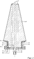
- the flushing device according to the invention shown in Fig. 1 consists of a ceramic sink 1 with a molded on the sink base 11 connecting pin 2.
- the sink side 11 is the side of the sink, which is located on the outside after installing the sink in the steel treatment pan.
- the connecting pin and the sink 1 are traversed by a plurality of gas passage openings 3 which open into the stone surface opposite the connecting pin 2.
- This stone surface corresponds to the side of the sink 1, which is in direct contact with the steel melt after installation in the steel treatment pan.
- the gas passage openings 3 are designed as lamellae in the form of thin slots. However, they can also be produced by directional porosity or formed by holes of any shape.
- the outside diameter of the connecting pin 2 is smaller than the surface of the sink base 11.
- the connecting pin 2 also has an external thread, with the aid of which a connecting sleeve made of metal can be screwed onto the connecting pin.
- the connecting sleeve 6 is provided at its two ends, ie, parallel to the bottom 11 and parallel to the underside 12 of the connecting pin, with flanges 13 and 14 extending radially outwards. After screwing the connecting sleeve 6 onto the connecting pin 2, the flange 14 lies firmly against the sink base 11, and thus prevents purging gas from escaping through the sink bottom 11 of the flange 13 corresponds.
- the sealing plate 4 is provided with a hole in the center, a gas supply pipe 5 being welded to the hole on the side of the sealing plate 4 facing away from the connecting pin underside 12.
- the Diameter of the gas supply pipe 5 slightly larger than the hole diameter.
- this sealing plate 4 is screwed, e.g. Cylinder head screws, screwed onto the connecting sleeve 6, the sealing plate 4 being moved to the underside 12 of the connecting pin and finally being pressed against it.
- both the sealing plate 4 and the flange 13 are provided with a plurality of threaded bores 7 in such a way that the cylinder head screws are screwed into the sealing plate and the flange 13 from the side of the sealing plate 4 facing away from the underside of the connecting pin and finally flush with the sealing plate 4 to lock.
- the seal 9 is limited to the surface areas of the connecting pin underside 12 and the sealing plate 5, which directly adjoin the connecting sleeve.
- a gas distribution space 8 is formed between the surface areas of the connecting pin underside 12 and the sealing plate 4, which are not covered by the seal.
- the gas distribution space is formed directly in the connecting pin underside. This gas distribution space 8 enables an unimpeded gas flow from the gas feed pipe 5 to the individual gas passage openings 3 to be ensured.
- an attack device for example on the outer surface of the union screw sleeve which surrounds the connection pin 2, is provided. a handle or recess.
- the purge gas is supplied from a gas source through the gas supply pipe 5 passed into the gas distribution space 8 and from there passed on through the gas supply openings 3 to the sink surface, from where it enters the molten steel.
- the size of these sink stones corresponds to the stones that are usual for steel treatment pans and are made from the materials that are usual for this application.
- the sink stones are bricked directly into the pan bottom or wall and survive a pan journey, i.e. the sink stone is only removed when the steel treatment pan is torn off.
- the side of the sink which is on the outside of the steel treatment pan after installing the sink, is additionally secured by a so-called wedge plate (not shown).
- This wedge plate is penetrated by the gas feed pipe 5 and supports the side of the sealing plate 4 facing away from the connecting pin underside 12 and is connected to the furnace floor support structure when the steel treatment pan is built up.
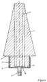
- the flushing device shown in FIG. 2 differs from the flushing device shown in FIG. 1 only in that the ceramic body is designed as a flushing cone.
- flushing cones are received in a known manner in operation in the conical openings of perforated bricks, which are located in the pan base or in the pan wall, and are mortared into the same.
- the thickness of the pan bottom corresponds essentially to the height of the perforated brick and the thickness of the perforated brick approximately to the height of the flushing cone.
- the tip of the cone protrudes above the perforated brick, and the purge gas then emerges from this area.
- the side of the flushing cone provided with the connecting pin is located on the outside of the steel treatment pan.
- This embodiment of the ceramic body makes it special preferred if the flange (14) formed on the outer surface of the connecting sleeve (6) corresponds in its dimensions to the diameter of the flushing cone base (11). This ensures a perfect seal.
- FIG. 3 shows a flushing device according to a second embodiment of the present invention. This embodiment is described below only with regard to its differences from the first embodiment (according to FIG. 1).
- the ceramic body is in this case designed as a sink, which was provided with a connecting pin 2 in the already known manner.
- a connecting pin 2 On this connecting pin 2, an existing union screw sleeve is screwed.
- the side of the coupling sleeve 6 facing the connecting pin underside 12 is penetrated by a gas supply pipe 5, the diameter of the opening provided in the coupling screw sleeve 6 being larger than the outside diameter of the gas supply pipe 5, so that the pipe can be moved in the opening in the longitudinal direction.
- a sealing plate 4 is welded to the gas supply pipe 5, flush with the pipe, which is encompassed by the union screw sleeve 6.
- this sealing plate 4 is moved by screwing the union screw sleeve 6 onto the connecting pin 2 on the connecting pin underside 12 and finally pressed against it. In this way, the transition between the gas distribution space 8 and the gas supply pipe 5, which is significantly smaller compared to the gas distribution space 8, is sealed.
- This seal can be increased even further if grub screws are screwed into the threaded holes 7 provided for this purpose, which are located in the side of the union screw sleeve 6 penetrated by the gas supply pipe 5, whereby these act on the sealing plate 4 and thereby an additional pressing of the sealing plate on the underside of the connecting pin 12 allows becomes.
- Fig. 4 illustrates a rinse cone according to a third embodiment of the present invention. Only the differences of this embodiment from the others are described below.
- the screw cap 6 and the gas supply pipe 5 form a one-piece device.
- the gas supply pipe passes through the side of the union screw socket facing the connecting pin underside 12 in the center and is flush with the inner surface of the union screw sleeve lying against the connecting pin computer side. To secure the gas supply pipe in this position, it can e.g. be welded on.
- This screw cap 6 is then screwed onto the connecting pin 2 together with the gas supply pipe in a single operation.
- the side of the union screw socket facing the underside of the union plug is moved towards the underside of the union pin and finally brought into sealing contact.
Landscapes
- Engineering & Computer Science (AREA)
- Mechanical Engineering (AREA)
- Treatment Of Steel In Its Molten State (AREA)
Applications Claiming Priority (4)
| Application Number | Priority Date | Filing Date | Title |
|---|---|---|---|
| DE9102698U | 1991-03-06 | ||
| DE9102698U DE9102698U1 (de) | 1991-03-06 | 1991-03-06 | Spülkegel für Stahlbehandlungspfannen |
| DE9109152U | 1991-07-24 | ||
| DE9109152U DE9109152U1 (de) | 1991-07-24 | 1991-07-24 | Keramischer Spülstein für Stahlbehandlungspfannen |
Publications (2)
| Publication Number | Publication Date |
|---|---|
| EP0502256A2 true EP0502256A2 (fr) | 1992-09-09 |
| EP0502256A3 EP0502256A3 (en) | 1992-12-09 |
Family
ID=25957930
Family Applications (1)
| Application Number | Title | Priority Date | Filing Date |
|---|---|---|---|
| EP19910121834 Withdrawn EP0502256A3 (en) | 1991-03-06 | 1991-12-19 | Gas bubbling device for the treatment of steel in a ladle |
Country Status (1)
| Country | Link |
|---|---|
| EP (1) | EP0502256A3 (fr) |
Cited By (4)
| Publication number | Priority date | Publication date | Assignee | Title |
|---|---|---|---|---|
| EP0609562A1 (fr) * | 1993-02-04 | 1994-08-10 | BECK u. KALTHEUNER, FEUERFESTE ERZEUGNISSE GmbH & CO. KG | Brique céramique de barbotage à gaz pour le traitement de l'acier en poche |
| DE4312981A1 (de) * | 1993-04-21 | 1994-10-27 | Dyko Industriekeramik Gmbh | Spüleinrichtung für metallurgische Gefäße |
| CN1047206C (zh) * | 1995-09-21 | 1999-12-08 | 普拉塞尔技术有限公司 | 用于开口容器的可控湍流吹洗的方法和装置 |
| WO2016050380A1 (fr) * | 2014-09-29 | 2016-04-07 | Refractory Intellectual Property Gmbh & Co. Kg | Dispositif de fixation destiné à un corps creux céramique cylindrique et brique de balayage au gaz céramique ignifuge comprenant un dispositif de fixation de ce type |
Family Cites Families (4)
| Publication number | Priority date | Publication date | Assignee | Title |
|---|---|---|---|---|
| DE1726983U (de) * | 1956-05-29 | 1956-07-26 | Aluminiumwerke Nuernberg G M B | Vorrichtung zur gaseinfuehrung in metallische schmelzen. |
| DE3505821C1 (de) * | 1985-02-20 | 1986-08-07 | Didier-Werke Ag, 6200 Wiesbaden | Huelse zum Einblasen von Feststoffen in eine Metallschmelze |
| DE3808367C1 (en) * | 1988-03-12 | 1990-02-01 | Didier-Werke Ag, 6200 Wiesbaden, De | Gas bubble brick |
| DE3833502A1 (de) * | 1988-10-01 | 1990-04-05 | Didier Werke Ag | Gasspuelstein |
-
1991
- 1991-12-19 EP EP19910121834 patent/EP0502256A3/de not_active Withdrawn
Cited By (9)
| Publication number | Priority date | Publication date | Assignee | Title |
|---|---|---|---|---|
| EP0609562A1 (fr) * | 1993-02-04 | 1994-08-10 | BECK u. KALTHEUNER, FEUERFESTE ERZEUGNISSE GmbH & CO. KG | Brique céramique de barbotage à gaz pour le traitement de l'acier en poche |
| DE4312981A1 (de) * | 1993-04-21 | 1994-10-27 | Dyko Industriekeramik Gmbh | Spüleinrichtung für metallurgische Gefäße |
| CN1047206C (zh) * | 1995-09-21 | 1999-12-08 | 普拉塞尔技术有限公司 | 用于开口容器的可控湍流吹洗的方法和装置 |
| WO2016050380A1 (fr) * | 2014-09-29 | 2016-04-07 | Refractory Intellectual Property Gmbh & Co. Kg | Dispositif de fixation destiné à un corps creux céramique cylindrique et brique de balayage au gaz céramique ignifuge comprenant un dispositif de fixation de ce type |
| EP3023173A1 (fr) * | 2014-09-29 | 2016-05-25 | Refractory Intellectual Property GmbH & Co. KG | Dispositif de fixation pour un corps creux en céramique cylindrique et pierre de lavage de gaz céramique ignifuge dotée d'un tel dispositif de fixation |
| CN106061651A (zh) * | 2014-09-29 | 2016-10-26 | 里弗雷克特里知识产权两合公司 | 用于圆柱形的陶瓷的空心体的固定装置和带有这样的固定装置的耐火的陶瓷的气体吹扫砖 |
| CN106061651B (zh) * | 2014-09-29 | 2017-07-21 | 里弗雷克特里知识产权两合公司 | 用于圆柱形的陶瓷的空心体的固定装置和带有这样的固定装置的耐火的陶瓷的气体吹扫砖 |
| US10330387B2 (en) | 2014-09-29 | 2019-06-25 | Refractory Intellectual Property Gmbh & Co. Kg | Securing device for a cylindrical ceramic hollow body and fireproof ceramic gas purging brick having such type of securing device |
| EA034188B1 (ru) * | 2014-09-29 | 2020-01-15 | Рифрэктори Интеллектчуал Проперти Гмбх Унд Ко. Кг | Крепежное приспособление для цилиндрической керамической полой детали и огнеупорный керамический газопродувочный кран с таким крепежным приспособлением |
Also Published As
| Publication number | Publication date |
|---|---|
| EP0502256A3 (en) | 1992-12-09 |
Similar Documents
| Publication | Publication Date | Title |
|---|---|---|
| DE2733665C2 (de) | Auswechselbare Verschleißteile für Schiebeverschlüsse | |
| DE3124359C2 (de) | Verfahren zur Reparatur bzw. Wiederherstellung von feuerfesten Verschleißteilen von Schieberverschlüssen | |
| EP0630712B1 (fr) | Busette de coulée immergée | |
| EP0363651B1 (fr) | Brique pour lavage au gaz | |
| DE4315709C2 (de) | Schiebeausguß für ein Stahlschmelze-Aufnahmegefäß | |
| DE2548854A1 (de) | Feuerfester stein mit einer durchlassoeffnung fuer fluessiges metall und verfahren zu dessen herstellung | |
| EP0502256A2 (fr) | Dispositif de barbotage à gaz pour le traitement de l'acier en poche | |
| DE3433123C2 (de) | Blasstein für metallurgische Pfannen und Verfahren zu seinem Einfügen in die Zustellung | |
| EP0204076B1 (fr) | Gaine d'injection de gaz ou de particules dans une poche contenant un bain métallurgique | |
| DE3735546A1 (de) | Anordnung zum verbinden eines metallteils mit einem formkoerper aus feuerfestmaterial | |
| DE102004050701B3 (de) | Abstichrohr für ein metallurgisches Schmelzgefäß | |
| DE4012952C2 (de) | Gasspüleinrichtung an einem metallurgischen Gefäß | |
| EP0858515B1 (fr) | Dispositif pour remplacement d'une lance de soufflage | |
| EP0249647B1 (fr) | Burette de coulée réfractaire | |
| EP0801721A1 (fr) | Buse remplacable pour reacteurs a haute temperature pourvus d'un revetement refractaire | |
| DE2527919C3 (de) | Vorrichtung zum Formen der Mörtelfugendichtung zwischen einem Kassettenschieber und einem Gefäß für metallische Schmelzen | |
| DE4324768C1 (de) | Anordnung zur Verbindung einer Stopfenstange für ein metallurgisches Gefäß mit ihrer Hebevorrichtung und für die Anordnung geeignete Stopfenstange sowie Verfahren zur Herstellung der Anordnung | |
| DE3510708C2 (fr) | ||
| DE9109152U1 (de) | Keramischer Spülstein für Stahlbehandlungspfannen | |
| EP0155255A2 (fr) | Dispositif de rinçage pour un récipient métallurgique | |
| WO1996025259A1 (fr) | Cuve a gaz se presentant sous la forme d'un dispositif de rinçage a interstices | |
| DE3511341C2 (de) | Feuerfester Ausguß für Stahl-Konverter und -Elektroöfen | |
| EP0359052B1 (fr) | Installation de brique de balayage de gaz pour récipients métallurgiques à fusion. | |
| DE19539621C1 (de) | Begasungsrührer für Leichtmetallschmelzen | |
| DE9206486U1 (de) | Keramischer Spülstein für Stahlbehandlungspfannen |
Legal Events
| Date | Code | Title | Description |
|---|---|---|---|
| PUAI | Public reference made under article 153(3) epc to a published international application that has entered the european phase |
Free format text: ORIGINAL CODE: 0009012 |
|
| AK | Designated contracting states |
Kind code of ref document: A2 Designated state(s): AT BE CH DE DK ES FR GB GR IT LI LU NL SE |
|
| PUAL | Search report despatched |
Free format text: ORIGINAL CODE: 0009013 |
|
| AK | Designated contracting states |
Kind code of ref document: A3 Designated state(s): AT BE CH DE DK ES FR GB GR IT LI LU NL SE |
|
| 17P | Request for examination filed |
Effective date: 19930602 |
|
| 17Q | First examination report despatched |
Effective date: 19941209 |
|
| STAA | Information on the status of an ep patent application or granted ep patent |
Free format text: STATUS: THE APPLICATION HAS BEEN WITHDRAWN |
|
| 18W | Application withdrawn |
Withdrawal date: 19950619 |