EP0502277A2 - Thermomètre à fibre optique pour oreille - Google Patents
Thermomètre à fibre optique pour oreille Download PDFInfo
- Publication number
- EP0502277A2 EP0502277A2 EP91310451A EP91310451A EP0502277A2 EP 0502277 A2 EP0502277 A2 EP 0502277A2 EP 91310451 A EP91310451 A EP 91310451A EP 91310451 A EP91310451 A EP 91310451A EP 0502277 A2 EP0502277 A2 EP 0502277A2
- Authority
- EP
- European Patent Office
- Prior art keywords
- temperature
- signal
- sheath
- ear thermometer
- thermopile
- Prior art date
- Legal status (The legal status is an assumption and is not a legal conclusion. Google has not performed a legal analysis and makes no representation as to the accuracy of the status listed.)
- Withdrawn
Links
Images



Classifications
-
- G—PHYSICS
- G01—MEASURING; TESTING
- G01J—MEASUREMENT OF INTENSITY, VELOCITY, SPECTRAL CONTENT, POLARISATION, PHASE OR PULSE CHARACTERISTICS OF INFRARED, VISIBLE OR ULTRAVIOLET LIGHT; COLORIMETRY; RADIATION PYROMETRY
- G01J5/00—Radiation pyrometry, e.g. infrared or optical thermometry
- G01J5/02—Constructional details
- G01J5/04—Casings
-
- G—PHYSICS
- G01—MEASURING; TESTING
- G01J—MEASUREMENT OF INTENSITY, VELOCITY, SPECTRAL CONTENT, POLARISATION, PHASE OR PULSE CHARACTERISTICS OF INFRARED, VISIBLE OR ULTRAVIOLET LIGHT; COLORIMETRY; RADIATION PYROMETRY
- G01J5/00—Radiation pyrometry, e.g. infrared or optical thermometry
- G01J5/02—Constructional details
- G01J5/025—Interfacing a pyrometer to an external device or network; User interface
-
- G—PHYSICS
- G01—MEASURING; TESTING
- G01J—MEASUREMENT OF INTENSITY, VELOCITY, SPECTRAL CONTENT, POLARISATION, PHASE OR PULSE CHARACTERISTICS OF INFRARED, VISIBLE OR ULTRAVIOLET LIGHT; COLORIMETRY; RADIATION PYROMETRY
- G01J5/00—Radiation pyrometry, e.g. infrared or optical thermometry
- G01J5/02—Constructional details
- G01J5/04—Casings
- G01J5/049—Casings for tympanic thermometers
-
- G—PHYSICS
- G01—MEASURING; TESTING
- G01J—MEASUREMENT OF INTENSITY, VELOCITY, SPECTRAL CONTENT, POLARISATION, PHASE OR PULSE CHARACTERISTICS OF INFRARED, VISIBLE OR ULTRAVIOLET LIGHT; COLORIMETRY; RADIATION PYROMETRY
- G01J5/00—Radiation pyrometry, e.g. infrared or optical thermometry
- G01J5/02—Constructional details
- G01J5/05—Means for preventing contamination of the components of the optical system; Means for preventing obstruction of the radiation path
-
- G—PHYSICS
- G01—MEASURING; TESTING
- G01J—MEASUREMENT OF INTENSITY, VELOCITY, SPECTRAL CONTENT, POLARISATION, PHASE OR PULSE CHARACTERISTICS OF INFRARED, VISIBLE OR ULTRAVIOLET LIGHT; COLORIMETRY; RADIATION PYROMETRY
- G01J5/00—Radiation pyrometry, e.g. infrared or optical thermometry
- G01J5/02—Constructional details
- G01J5/08—Optical arrangements
-
- G—PHYSICS
- G01—MEASURING; TESTING
- G01J—MEASUREMENT OF INTENSITY, VELOCITY, SPECTRAL CONTENT, POLARISATION, PHASE OR PULSE CHARACTERISTICS OF INFRARED, VISIBLE OR ULTRAVIOLET LIGHT; COLORIMETRY; RADIATION PYROMETRY
- G01J5/00—Radiation pyrometry, e.g. infrared or optical thermometry
- G01J5/02—Constructional details
- G01J5/08—Optical arrangements
- G01J5/0818—Waveguides
- G01J5/0821—Optical fibres
-
- G—PHYSICS
- G01—MEASURING; TESTING
- G01J—MEASUREMENT OF INTENSITY, VELOCITY, SPECTRAL CONTENT, POLARISATION, PHASE OR PULSE CHARACTERISTICS OF INFRARED, VISIBLE OR ULTRAVIOLET LIGHT; COLORIMETRY; RADIATION PYROMETRY
- G01J5/00—Radiation pyrometry, e.g. infrared or optical thermometry
- G01J5/10—Radiation pyrometry, e.g. infrared or optical thermometry using electric radiation detectors
- G01J5/12—Radiation pyrometry, e.g. infrared or optical thermometry using electric radiation detectors using thermoelectric elements, e.g. thermocouples
- G01J5/14—Electrical features thereof
- G01J5/16—Arrangements with respect to the cold junction; Compensating influence of ambient temperature or other variables
-
- G—PHYSICS
- G01—MEASURING; TESTING
- G01J—MEASUREMENT OF INTENSITY, VELOCITY, SPECTRAL CONTENT, POLARISATION, PHASE OR PULSE CHARACTERISTICS OF INFRARED, VISIBLE OR ULTRAVIOLET LIGHT; COLORIMETRY; RADIATION PYROMETRY
- G01J5/00—Radiation pyrometry, e.g. infrared or optical thermometry
- G01J5/70—Passive compensation of pyrometer measurements, e.g. using ambient temperature sensing or sensing of temperature within housing
Definitions
- thermometers intended to measure the core temperature of a living being and, more specifically, to measure that temperature by measuring and analyzing infrared radiation from the tympanic membrane.
- thermometers The measurement of the core temperature of a body has been long used in medical diagnosis and treatment.
- the most common method has been to measure temperature with a tubular glass thermometer containing mercury by insertion in the mouth or rectum, placing under the arm, etc. Breakage of those thermometers in use is a constant danger.
- ill or injured patients may bite through the thermometer or make abrupt movements which cause breakage during the 2-3 minutes required to obtain an accurate maximum temperature.
- mouth or rectum temperatures may not always be representative of true body core temperature and do not change as rapidly as core temperature.
- These thermometers require sterilization when used with a number of patients to prevent cross-contamination and must be shaken down to reduce the displayed temperature since they only measure increasing temperature. These steps take significant time in a busy medical office or hospital and may be overlooked with serious consequences.
- the tympanic membrane within the ear canal is an excellent site for determination of the core temperature of a body due to its proximity to the external carotid artery which supplies blood to the hypothalamus.
- the hypothalamus has been shown to be the site of the body's core temperature. Patients show changes in core temperature at the tympanic membrane prior to peripheral sites such as the mouth or rectum. This allows the attending physician to more quickly respond to possible complications.
- Prior ear thermometers suffer from a number of problems. They are difficult to calibrate to provide accurate temperatures in varying ambient temperature conditions and have repeatability problems.
- the previous ear thermometers used rigid metal tube "waveguides" using a metal coating such as gold to increase the reflectivity of the inner surface. Since these work according to principles of classic optics with the infrared radiation bouncing off the walls from one end to the other there are severe losses with a tube of the necessary length. For example, assuming a reflectivity of 97%, 20 "bounces" will reduce the signal by about 50%. The tube must be straight and must have a large diameter to reduce the number of bounces. Typical of such ear thermometers is that described by Fraden in U.S. Patent 4,797,840.
- thermometer Another prior ear thermometer is described by O'Hara et al in U.S. Patent 4,790,324.
- This thermometer uses a probe including waveguide tube to direct infrared radiation to a thermopile which is kept at a constant temperature by a heater.
- the probe is connected to a chopper unit which is kept at a constant temperature by a second heater system to establish a reference temperature. Then the probe is removed from the chopper, a disposable speculum is placed over the probe which is then inserted in the patient's ear and a temperature reading is taken.
- This complex calibration method is prone to errors, requires several heaters and may give erroneous readings if the calibration targets are not at the precise intended temperatures or there is a delay between calibration and ear temperature measurement.
- thermometers of improved simplicity, accuracy and usefulness.
- Another object of this invention is to provide an improved, low-loss, means for conveying infrared radiation from the tympanic membrane to a temperature detector.
- Still another object is to provide an ear thermometer of improved accuracy and resistance to errors resulting from varying ambient conditions.
- a further object is to provide an ear thermometer capable of accurate compensation or nulling of extraneous signals immediately prior or immediately after temperature measurement.
- Yet another object is to provide an improved disposable sheath for the probe of an ear thermometer.
- an ear thermometer which includes a probe for insertion into the ear to a location adjacent to, but not in contact with, the tympanic membrane, an infrared radiation transmitting flexible fiber optic light guide within the probe for transmitting infrared radiation emitted by the tympanic membrane to a thermopile in an adjacent housing, a disposable sheath over the probe having an infrared transparent window portion covering the fiber optic end, electronic circuitry in the housing to compensate for ambient temperature variations, detector drift, etc. and provide an accurate temperature readout and a display for indicating the temperature measured.
- the unit may have any suitable configuration.
- a "pistol grip" shape has been found to be convenient, with the electronic components and batteries in the handle.
- the flexible fiber optic light guide allows placement of the detector in the body of the handpiece to allow better thermal and electrical shielding of the detector.
- the fibers have a small numerical aperture so they look at only the tympanic membrane and do not transmit radiation from surrounding ear tissue. Since the fiber optic has very low transmission losses, a longer transmission path may be used and a smaller detector may be used for lower noise.
- thermometer is a self-contained, battery powered unit. If rechargeable batteries are used, the unit may be stored between uses in a recharger stand which may have an attached container for a supply of disposable probe sheaths. The unit is easily portable, typically being carried in a small case with a supply of sheaths.
- a housing 10 contains the electronic and other components and bears a probe 12 and a temperature readout display 14.
- Display 14 is typically a conventional liquid crystal display. The temperature is displayed in relatively large characters on either the celsius or fahrenheit scales.
- Display 14 also typically shows the mode, typically oral, rectal, tympanic or scan, "ready” to indicate that the system is ready for use, “calibrate” during the (very short) system calibration cycle and power supply status (typically “recharge” when a rechargeable battery requires recharging prior to use and a bar scale indicating the extent of charge from empty to full).
- the display 14 provides system status under the direction of a microprocessor. Other system characteristics may be displayed, if desired. Alternatively, a single display line, capable of showing 8 characters, may be used to selectively or in sequence display the "ready", “calibrate”, etc., displays, if desired.
- housing may have any suitable configuration, the "pistol" shape shown is preferred for ease of use.
- the user's hand surrounds the lower portion of housing 10, leaving display area 14 visible, and probe 12 is inserted into the ear canal.
- a disposable sheath 16 shown in Figure 2 covers the end of probe 12 and is shaped to permit the desired insertion distance so that the end of probe 12 is near, but not in contact, with the tympanic membrane.
- a trigger switch 18 is pressed to begin the temperature calibration and measurement sequence.
- a pair of mode switches 15 and 17 that allow the operator to toggle from one mode to another are located above display 14.
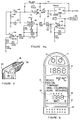
- the central area of display 14, the area below switches 15 and 17 in Figure 1b, is shown in enlarged detail in Figure 6.
- Depressing switch 17 a single time when in the tympanic mode causes the device to change to the scan mode, showing the temperature adjacent to the detector. Pressing switch 17 twice when in the tympanic mode changes to the oral mode, while pressing switch an additional time moves to the rectal mode.
- the scan, oral and rectal displays are simply equivalents that one would expect to correspond to the tympanic reading obtained. These are for the convenience of clinicians who normally use the oral or rectal method of thermometry.
- the mode in use is shown in area 13 in Figure 6, as are displays indicating that the calibration sequence is in progress, that the battery is being recharged and the unit is on and "ready". While all of these indicia are shown together in Figure 6, if liquid crystal display means are used, only the active one of these display words will be shown at a time.
- Pressing switch 15 twice changes the reading from Fahrenheit to Celsius and lights the "°C” instead of the "°F” on the display as shown. To recall the last five temperature readings, switch 15 is pressed once, then switch 17 is pressed once. The last five temperature readings are stepped through by pressing switch 15 repeatedly and displayed at area 23. Which of the last five readings is displayed is indicated by numbers 25 (only one of which is displayed at a time). Pressing trigger switch 18 returns to the default settings and displays the last reading taken.
- the display also preferably includes a conventional bar shaped liquid crystal display 19 connected to battery 24 so as to indicate battery condition from fully discharged to fully charged by increasing bar length. Also, an audible alarm 21 (as seen in Figure 1b) is preferably included to signal very low battery condition with suitable conventional connections to battery 24.
- the internal structure of the ear thermometer is schematically illustrated in Figures 1c-1f.
- the lower portion 20 of housing 12 is detachable at connection 22 which may be any suitable arrangement, such as an overlapping friction fit, including conventional ball-and-detent means, if desired.
- a plurality of stacked sheaths 16 are contained in lower portion 20 for easy removal and installation over probe 12. After each ear temperature measurement the sheath 16 over probe 12 is slipped off and disposed of and a new sheath from housing 20 is installed.
- housing 10 contains a power supply 24, typically a rechargeable battery having recharging contacts 26 accessible through a pair of openings or the like in housing 10.
- Liquid crystal display panel 14 is preferably backed with a conventional display back light 28.
- the space within housing 10 above the battery and display houses the various electronic components in space 30.
- Probe 12 contains optical fiber bundle 32 surrounded by insulation 34 and a disposable sheath 16. If desired, insulation 34 may be eliminated.
- Thermopile detector 50 as detailed below is located at the inner end of fiber optics 32. If desired, detector 50 may be located in space 30 and optical fibers 32 maybe be curved or bent between the end of probe 12 and the detector.
- a stripper collet 36 is preferably located around housing 12 adjacent to sheath 16. Collet is movable a short distance toward sheath 16, to "pop" the sheath off of the housing into a disposal container without requiring the operator to touch the possibly contaminated sheath after use. Installation of a new sheath 16 will return collet 36 to the position shown in Figure 1c. If desired, an extension may be provided above the upper end of trigger (which is hinged at the upper end as seen in Figure 1c) extending upwardly and forwardly into contact with collet 36, to move collet 36 forwardly, so that a sheath is pushed off every time trigger 18 is fully pressed in.
- any suitable optical fibers may be used. Excellent results are obtained with chalcogenide glass fibers of the sort available from Infrared Fiber Systems, Inc. Fibers typically have diameters of from about 120 to 440 microns and are used in bundles encased in a plastic sheath. Since the optical fiber length in our unit is rather short, the usable infrared bandwidth should be about 2 to 12 microns.
- the fiber bundle may have any suitable diameter, preferably in the .090 to .115 inch range. Since the fiber bundle is thin, external ambient temperature will have little adverse effect on the fibers. If desired, a thin layer of conventional polyethylene foam insulation may be provided to further reduce any outside temperature effects.
- thermopile may be placed in the optimum location in housing 10, with maximum isolation from outside temperature variations, with the fiber bundle curved between probe 12 and the thermopile in space 30.
- the internal configuration of sheath 16 is configured to conform to the outer surface of probe 12.
- the length of tip portion 40 is selected to be sufficient to allow the end 42 to be inserted into the ear canal to a position adjacent to and spaced from the tympanic membrane while the generally conical wall 44 prevents insertion so far as to allow end 42 to contact the tympanic membrane.
- the window at end 42 should be very thin, on the order of 0.002 to 0.004 inch thick, to avoid any significant absorption of infrared radiation passing therethrough.
- Sheath 16 is made from any suitable material having low infrared radiation absorption characteristics, such as polyethylene.
- Sheath 16 is made by injection molding using a mold that has a movable mandrel or piston adjacent to the window end 42.
- the piston When molten plastic is injected into the mold, the piston is slightly moved away from the opposite wall of the mold in the window area, allowing the plastic to flow easily into that area. Then, prior to cooling and solidification of the plastic, the piston is moved toward the opposite mold wall, compressing and forcing plastic out of that area until the window end 42 has a thickness of about 0.001 to 0.002 inch.
- This method permits rapid production of uniformly high quality sheaths while producing an infrared transmitting window of uniform thickness and high clarity so that the maximum quantity of infrared radiation from the tympanic membrane passes to the optical fiber.
- thermopile detector 50 typically a model 2m Detector available from Dexter Research Center, Inc., accepts an infrared input signal from the optical fiber (not shown) within probe 12. Detector 50 transduces the heat signal to an electrical signal which is amplified by amplifiers 52 and 54, typically each an OP221 from Linear Technology, Inc.. Because of the differential connection, amplifiers 52 and 54 provide very good thermal stability of the input amplifier and increase the signal-to-noise ratio.
- Amplifier 56 (typically an LP324 from Linear Technology) provides low-pass filtering and boostering for analog-to-digital converter 58, typically an AD7579 from Analog Devices, Inc.
- Converter 58 converts the analog signal to digital code and sends it to microprocessor 60, typically a 65512 U5 from Oki Technology, Inc.
- microprocessor 60 controls switches 62, 64, 66, and 68 for receiving information from detector 50, checks the power supply by turning on switch 70, accepts power supply voltage via switch 70 and amplifier 56, receives ambient temperature information from the independent transducer or resistor 72, typically an AD590 from International Components, and amplifier 74, typically another LP324. Final information is sent to display 14.
- Switches 62-68 are simplified schematic parts of mode switch 69 (which includes both switches 15 and 17 as seen in Figure 1b), typically an ADG221 from, Analog Devices.
- Amplifier 76 typically another LP324, splits voltage from the single power supply, typically from a rechargeable battery, to bipolar voltage, indicated as -VCC and +VCC.
- Voltage reference 78 typically an AD580 from International Components, provides stable voltage for converter 58 and for temperature transduction.
- each chip performs several functions.
- amplifiers 52 and 54 are parts of a single OP221 and measure input signal, thermopile detector 50 resistance, null offsetting and amplify the signal from resistor 72.
- Amplifiers 56, 74 and 76 may be parts of a single LP324 which is used for converting ambient temperature (amplifier 74), splitting voltage (amplifier 76) and low pass filtering and checking battery voltage (amplifier 56). With this arrangement, only 5 main chips are required.
- Trigger switch 18 resets the system and initiates another temperature reading.
- Mode switch 17 changes the mode from tympanic, scan, oral and rectal modes as described above.
- Switch 15 when open causes the display to default to a temperature reading on the Fahrenheit scale and when closed changes the display to Celsius.
- thermopile detector 50 depends not only on the input signal from the temperature source (here the tympanic membrane) but also on the detector's own internal temperature. Thus, room temperature fluctuations will cause drift and inaccuracy in the measurement. In the past, attempts were made to overcome this problem by placing the thermopile in a metal housing and attempting to maintain that housing at a constant temperature with a heater/cooler under control of a thermocouple in contact with the thermopile. Unfortunately, the temperature of the thermocouple does not exactly equal the temperature of the detector and this arrangement requires additional circuitry and power.
- thermopile Since the resistance of the detector depends on its temperature, we measure the resistance of the thermopile in the circuit of Figure 3 to determine the precise thermopile temperature, i.e., the thermopile acts as its own thermometer. This resistance is used to compensate the measured signal to obtain an accurate, drift-free reading.
- thermopile detector 50 the thermopile consists of many thermocouples connected together. Each thermocouple consists of a "hot” (signal) junction and a “cold” (reference) junction. The measured voltage is given by the difference between these junctions.
- the input temperature signal affects not only the hot junction of the thermopile but because of its very small size and thermoconductivity the input signal also changes the temperature of the cold junction. Different input temperatures will cause different changes in the temperature of the cold junction.
- a calibration source typically a reference source or chopper controller, approximately equal to the expected temperature signal (e.g. 98°F. for a thermometer to be used with humans) was used.
- the input temperature signal can vary over a relatively large range and the calibration error will increase in proportion to the difference between the temperature of the reference and the unknown source (the patient's tympanic membrane).
- our microprocessor 60 performs the calibration immediately after the measurement. The temperatures of the thermopile hot and cold junctions stabilize during measurement. Upon completion of the measurement, the microprocessor interrupts the incoming signal, so that the output of the thermopile should be zero. Any actual signal is a result of cold junction error and is deleted from the measured signal by the microprocessor to produce a precisely accurate temperature signal.
- the system operates in several hardware modes, depending upon the positions of switches 62, 64, 66 and 68 as controlled by microprocessor 60.
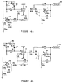
- Figures 4a through 4f illustrate these different switch arrangements and the resulting functions in simplified schematic circuit form.
- FIG 4a shows the simplified circuit configuration during measurement of the input signal from thermopile detector 50. Switches 62, 64 and 68 are turned off while switch 66 is turned on. An analog signal corresponding to the input signal is passed to analog to digital converter 58 (not seen in Figure 4a) through output 84. This analog portion of the circuit operates as a differential amplifier with gain of about 2000.
- Figure 4b shows the simplified circuit configuration during another measurement of the signal from the thermopile detector 50. However, in this case switches 62, 64, 66 and 68 are all turned off, which adds resistor 86 to the circuit so that the conditions of signal measurement have been changed. By alternately measuring the detector signal with the circuits shown in Figures 4a and 4b, better accuracy and stability are obtained.
- thermopile detector 50 output signal (differential amplifier 58 input) is equal for both inputs from amplifiers 52 and 54, so the output should be zero. Therefore, any output voltage is totally error (thermodrift of input voltage and current, errors generated by contact thermopotentials, by electro-magnetic fields, etc.) so that this signal should be subtracted from the main signal, which was received in the circuit arrangement of Figure 4a. Thus, corrections are rapidly and accurately made for these errors as microprocessor 60 goes through the programmed operation sequence.
- thermopile detector 50 measures resistance of the thermopile detector 50 to provide information about the actual thermopile temperature.
- switches 62, 66 and 68 are turned off and switch 64 is turned on by microprocessor 60.
- a resistor bridge which is supplied by electric current through resistor 92 has three known values, resistors 86, 88 and 90. Changes in resistance in this bridge are proportional to temperature changes in detector 50. Because of the high system gain it is possible to determine detector 50 temperatures on the order of 0.05°C. Thus, errors resulting from changes in thermopile temperature can be easily compensated for by microprocessor 60.
- Figure 4e illustrates the simplified circuit configuration for measuring ambient temperature from an independent transducer. This allows the ear thermometer to be checked against industry standards over a wide range of temperatures. In this case, switches 62 and 66 are turned off and switches 64 and 68 are turned on. The temperature transducer, resistor 72 is connected through amplifier 74 (which converts °F. to °C.) is connected to the differential amplifier input. The output will correspond to 100mv/1°C. Comparison to standard temperature sources is accomplished by a conventional calibration heater.
- Figure 5 is a detail section view, corresponding to the upper portion of the embodiment shown in Figure 1c.
- fiber optic 32 is curved and detector 50 is placed further back in housing 20, partially within container 30.
- the fiber optic system of this invention it is not necessary that the light guide be absolutely straight, since our fiber optics are fully effective when curved.
Landscapes
- Physics & Mathematics (AREA)
- General Physics & Mathematics (AREA)
- Spectroscopy & Molecular Physics (AREA)
- Engineering & Computer Science (AREA)
- Human Computer Interaction (AREA)
- Measuring And Recording Apparatus For Diagnosis (AREA)
- Radiation Pyrometers (AREA)
Applications Claiming Priority (2)
| Application Number | Priority Date | Filing Date | Title |
|---|---|---|---|
| US664294 | 1991-03-04 | ||
| US07/664,294 US5167235A (en) | 1991-03-04 | 1991-03-04 | Fiber optic ear thermometer |
Publications (2)
| Publication Number | Publication Date |
|---|---|
| EP0502277A2 true EP0502277A2 (fr) | 1992-09-09 |
| EP0502277A3 EP0502277A3 (en) | 1993-06-09 |
Family
ID=24665422
Family Applications (1)
| Application Number | Title | Priority Date | Filing Date |
|---|---|---|---|
| EP19910310451 Withdrawn EP0502277A3 (en) | 1991-03-04 | 1991-11-13 | Fiber optic ear thermometer |
Country Status (3)
| Country | Link |
|---|---|
| US (1) | US5167235A (fr) |
| EP (1) | EP0502277A3 (fr) |
| JP (1) | JPH06154173A (fr) |
Cited By (6)
| Publication number | Priority date | Publication date | Assignee | Title |
|---|---|---|---|---|
| WO1997019332A1 (fr) * | 1995-11-18 | 1997-05-29 | Braun Aktiengesellschaft | Thermometre a rayonnement infrarouge |
| WO1997019331A1 (fr) * | 1995-11-18 | 1997-05-29 | Braun Aktiengesellschaft | Procede d'evaluation du signal emis par un thermometre a infrarouge et thermometre a infrarouge approprie |
| DE19724054A1 (de) * | 1997-06-07 | 1998-12-10 | Braun Ag | Strahlungsthermometer und Schutzkappe dafür |
| EP1077046A4 (fr) * | 1998-05-06 | 2002-05-29 | Matsushita Electric Industrial Co Ltd | Thermometre auriculaire a usage feminin |
| EP1190668A4 (fr) * | 1999-06-11 | 2003-02-05 | Omron Tateisi Electronics Co | Thermometre clinique du type auriculaire |
| EP1519172A1 (fr) * | 2003-09-26 | 2005-03-30 | ARTSANA S.p.A. | Procédé pour la mesure de la température corporelle humaine à l'aide d'un thermomètre à infrarouge , et un thermomètre pour mettre en application ledit procédé |
Families Citing this family (140)
| Publication number | Priority date | Publication date | Assignee | Title |
|---|---|---|---|---|
| US5179936A (en) * | 1984-10-23 | 1993-01-19 | Intelligent Medical Systems, Inc. | Disposable speculum with membrane bonding ring |
| US5653238A (en) * | 1988-12-06 | 1997-08-05 | Exergen Corporation | Radiation detector probe |
| EP0445783B1 (fr) * | 1990-03-08 | 1996-02-07 | Ivac Corporation | Sonde thermiquement isolée |
| USD337954S (en) | 1991-01-24 | 1993-08-03 | Shigeru Makita | Thermometer |
| US5419311A (en) * | 1993-02-18 | 1995-05-30 | Olympus Optical Co., Ltd. | Endoscope apparatus of a type having cover for covering the endoscope |
| US5368038A (en) * | 1993-03-08 | 1994-11-29 | Thermoscan Inc. | Optical system for an infrared thermometer |
| JP3184659B2 (ja) * | 1993-04-01 | 2001-07-09 | テルモ株式会社 | 体温計 |
| US5479931A (en) * | 1993-11-18 | 1996-01-02 | Thermoscan, Inc. | IR thermometer |
| JPH0856908A (ja) * | 1994-08-19 | 1996-03-05 | Terumo Corp | 鼓膜温度計 |
| US5626139A (en) * | 1994-09-23 | 1997-05-06 | Artech Industries, Inc. | Tympanic thermometer |
| US5725308A (en) * | 1994-12-23 | 1998-03-10 | Rtd Technology, Inc. | Quick registering thermometer |
| US5673692A (en) * | 1995-02-03 | 1997-10-07 | Biosignals Ltd. Co. | Single site, multi-variable patient monitor |
| USD377910S (en) * | 1995-07-31 | 1997-02-11 | Braun Aktiengesellschaft | Thermometer |
| USD370860S (en) | 1995-08-16 | 1996-06-18 | Exergen Corporation | Infrared ear thermometer |
| US5820264A (en) * | 1996-03-25 | 1998-10-13 | Oriental System Technology, Inc. | Tympanic thermometer arrangement |
| USD388343S (en) * | 1996-04-22 | 1997-12-30 | Omron Corporation | Ear-inserted-type clinical thermometer |
| IL118050A (en) * | 1996-04-26 | 2000-07-26 | Katzir Avraham | Infrared-transmitting-fiber-optic-cable-based device for non-contact thermometry |
| US5666956A (en) * | 1996-05-20 | 1997-09-16 | Buchert; Janusz Michal | Instrument and method for non-invasive monitoring of human tissue analyte by measuring the body's infrared radiation |
| US6689091B2 (en) | 1996-08-02 | 2004-02-10 | Tuan Bui | Medical apparatus with remote control |
| US5895371A (en) * | 1996-08-27 | 1999-04-20 | Sabratek Corporation | Medical treatment apparatus and method |
| US6605057B2 (en) | 1996-10-24 | 2003-08-12 | Medtronic Ave, Inc. | Reinforced monorail balloon catheter |
| US6030117A (en) | 1996-11-12 | 2000-02-29 | Trutek, Inc. | Tympanic thermometer probe cover |
| US5833367A (en) | 1996-11-12 | 1998-11-10 | Trutek, Inc. | Tympanic thermometer probe cover |
| US5790040A (en) * | 1996-12-13 | 1998-08-04 | Interactive Technologies, Inc. | Battery-operated security system sensors |
| AU7807898A (en) | 1997-06-03 | 1998-12-21 | Trutek, Inc. | Tympanic thermometer with modular sensing probe |
| US6056435A (en) | 1997-06-24 | 2000-05-02 | Exergen Corporation | Ambient and perfusion normalized temperature detector |
| EP1304555B1 (fr) * | 1997-07-16 | 2007-05-23 | Terumo Kabushiki Kaisha | Thermomètre tympanique |
| USD402905S (en) | 1997-08-27 | 1998-12-22 | Matsushita Electric Industrial Co., Ltd. | Electronic clinical thermometer |
| USD402904S (en) | 1997-08-27 | 1998-12-22 | Matsushita Electric Industrial Co., Ltd. | Electronic clinical thermometer |
| US5991700A (en) * | 1997-10-15 | 1999-11-23 | Sherwood Services, A.G. | EMI stability indicator for tympanic thermometer |
| WO1999057528A1 (fr) | 1998-05-02 | 1999-11-11 | Focal, Inc. | Controleur de puissance pour source lumineuse |
| US5967992A (en) | 1998-06-03 | 1999-10-19 | Trutex, Inc. | Radiometric temperature measurement based on empirical measurements and linear functions |
| US6292685B1 (en) * | 1998-09-11 | 2001-09-18 | Exergen Corporation | Temporal artery temperature detector |
| IL126224A0 (en) * | 1998-09-15 | 1999-05-09 | Gerlitz Jonathan | Ear thermometer and detector therefor |
| US6398727B1 (en) | 1998-12-23 | 2002-06-04 | Baxter International Inc. | Method and apparatus for providing patient care |
| US6231560B1 (en) * | 1999-02-10 | 2001-05-15 | Baxter International Inc | Method and apparatus for automatically controlling the level of medication |
| US6123454A (en) | 1999-06-11 | 2000-09-26 | Trutek, Inc. | Tympanic thermometer disposable probe cover with further stretching prevention structure |
| US6450970B1 (en) * | 1999-11-16 | 2002-09-17 | Ron Mahler | Method and device for diagnosing an inflammatory process |
| DE19954756A1 (de) * | 1999-11-17 | 2001-05-31 | Odim Gmbh | Gerät und Verfahren zur Untersuchung von biologischem Gewebe |
| US6319206B1 (en) * | 1999-11-24 | 2001-11-20 | Exergen Corporation | Temporal thermometer disposable cap |
| US6425688B1 (en) * | 2000-04-21 | 2002-07-30 | Actherm Inc. | Infrared temperature wave guide device |
| JP3945189B2 (ja) * | 2001-06-01 | 2007-07-18 | オムロンヘルスケア株式会社 | 赤外線体温計 |
| US20030125662A1 (en) | 2002-01-03 | 2003-07-03 | Tuan Bui | Method and apparatus for providing medical treatment therapy based on calculated demand |
| US10173008B2 (en) | 2002-01-29 | 2019-01-08 | Baxter International Inc. | System and method for communicating with a dialysis machine through a network |
| US8775196B2 (en) | 2002-01-29 | 2014-07-08 | Baxter International Inc. | System and method for notification and escalation of medical data |
| US8234128B2 (en) | 2002-04-30 | 2012-07-31 | Baxter International, Inc. | System and method for verifying medical device operational parameters |
| US6980708B2 (en) * | 2002-05-13 | 2005-12-27 | Bartec Gmbh | Device for fibre optic temperature measurement with an optical fibre |
| US6850789B2 (en) * | 2002-07-29 | 2005-02-01 | Welch Allyn, Inc. | Combination SPO2/temperature measuring apparatus |
| US6968222B2 (en) | 2003-05-02 | 2005-11-22 | Oculir, Inc. | Methods and device for non-invasive analyte measurement |
| US6975892B2 (en) | 2003-10-21 | 2005-12-13 | Oculir, Inc. | Methods for non-invasive analyte measurement from the conjunctiva |
| US6958039B2 (en) | 2003-05-02 | 2005-10-25 | Oculir, Inc. | Method and instruments for non-invasive analyte measurement |
| US7107088B2 (en) * | 2003-08-25 | 2006-09-12 | Sarnoff Corporation | Pulse oximetry methods and apparatus for use within an auditory canal |
| US20050059870A1 (en) * | 2003-08-25 | 2005-03-17 | Aceti John Gregory | Processing methods and apparatus for monitoring physiological parameters using physiological characteristics present within an auditory canal |
| US20050085733A1 (en) * | 2003-10-17 | 2005-04-21 | Anthony Wong | Ear thermometer illumination system |
| US20050083991A1 (en) * | 2003-10-17 | 2005-04-21 | Anthony Wong | Probe cover storage system for ear thermometer |
| EP1530034A1 (fr) * | 2003-11-05 | 2005-05-11 | Microlife Intellectual Property GmbH | Thermomètre infrarouge et un procédé pour la déterminer la température |
| US7668325B2 (en) | 2005-05-03 | 2010-02-23 | Earlens Corporation | Hearing system having an open chamber for housing components and reducing the occlusion effect |
| US7955249B2 (en) * | 2005-10-31 | 2011-06-07 | Earlens Corporation | Output transducers for hearing systems |
| US8401212B2 (en) | 2007-10-12 | 2013-03-19 | Earlens Corporation | Multifunction system and method for integrated hearing and communication with noise cancellation and feedback management |
| US7867160B2 (en) | 2004-10-12 | 2011-01-11 | Earlens Corporation | Systems and methods for photo-mechanical hearing transduction |
| US8295523B2 (en) | 2007-10-04 | 2012-10-23 | SoundBeam LLC | Energy delivery and microphone placement methods for improved comfort in an open canal hearing aid |
| TWM270787U (en) * | 2004-08-02 | 2005-07-21 | Mesure Technology Co Ltd | Ear temperature detector |
| US20060036138A1 (en) * | 2004-08-06 | 2006-02-16 | Adam Heller | Devices and methods of screening for neoplastic and inflammatory disease |
| TWI273224B (en) * | 2005-02-12 | 2007-02-11 | Radiant Innovation Inc | Protective cover structure of an ear thermometer |
| US9037247B2 (en) | 2005-11-10 | 2015-05-19 | ElectroCore, LLC | Non-invasive treatment of bronchial constriction |
| TW200800098A (en) * | 2006-06-16 | 2008-01-01 | Radiant Innovation Inc | Infrared clinical thermometer |
| US20080125749A1 (en) * | 2006-08-29 | 2008-05-29 | Boston Scientific Scimed, Inc. | Self-powered medical devices |
| TW200841859A (en) * | 2007-04-27 | 2008-11-01 | Actherm Inc | Infrared thermometer |
| US8100886B2 (en) * | 2007-08-15 | 2012-01-24 | Visiomed Group Sa | Aspirator assembly |
| USD594968S1 (en) * | 2007-08-15 | 2009-06-23 | Eric Sebban | Aspirator assembly |
| US20090076441A1 (en) * | 2007-08-15 | 2009-03-19 | Eric Sebban | Aspirator assembly |
| US20090074027A1 (en) * | 2007-09-18 | 2009-03-19 | Vatell Corporation | Heat flux sensor incorporating light conveyance |
| US20090125330A1 (en) * | 2007-11-09 | 2009-05-14 | Eric Sebban | Non-invasive medical data collecting assembly |
| US8396239B2 (en) | 2008-06-17 | 2013-03-12 | Earlens Corporation | Optical electro-mechanical hearing devices with combined power and signal architectures |
| WO2009155361A1 (fr) | 2008-06-17 | 2009-12-23 | Earlens Corporation | Dispositifs auditifs électro-mécaniques optiques présentant une architecture combinant puissance et signal |
| WO2009155358A1 (fr) | 2008-06-17 | 2009-12-23 | Earlens Corporation | Dispositifs d’audition électromécaniques optiques dotés de composants d’alimentation et de signal séparés |
| US8057679B2 (en) | 2008-07-09 | 2011-11-15 | Baxter International Inc. | Dialysis system having trending and alert generation |
| US10089443B2 (en) | 2012-05-15 | 2018-10-02 | Baxter International Inc. | Home medical device systems and methods for therapy prescription and tracking, servicing and inventory |
| US20100046579A1 (en) * | 2008-08-21 | 2010-02-25 | Jeff Baker | Rechargeable Ear Thermometer |
| EP3509324B1 (fr) | 2008-09-22 | 2023-08-16 | Earlens Corporation | Dispositifs à armature équilibrée et procédés d'écoute |
| US8554579B2 (en) | 2008-10-13 | 2013-10-08 | Fht, Inc. | Management, reporting and benchmarking of medication preparation |
| US8186876B2 (en) * | 2009-04-20 | 2012-05-29 | Welch Allyn, Inc. | Calibrated assembly for IR thermometer apparatus |
| DK2438768T3 (en) | 2009-06-05 | 2016-06-06 | Earlens Corp | Optically coupled acoustically mellemøreimplantatindretning |
| US9544700B2 (en) | 2009-06-15 | 2017-01-10 | Earlens Corporation | Optically coupled active ossicular replacement prosthesis |
| CN102598713A (zh) | 2009-06-18 | 2012-07-18 | 音束有限责任公司 | 用于听力系统的耳膜可植入装置及方法 |
| CN102640435B (zh) | 2009-06-18 | 2016-11-16 | 伊尔莱茵斯公司 | 光学耦合的耳蜗植入系统及方法 |
| WO2011005479A2 (fr) | 2009-06-22 | 2011-01-13 | SoundBeam LLC | Systèmes et procédés de conduction osseuse à couplage optique |
| BRPI1016075A2 (pt) | 2009-06-22 | 2016-05-10 | SoundBeam LLC | dispositivo para transmitir som para um ouvido de um usuário e métodos associados. |
| US8715154B2 (en) | 2009-06-24 | 2014-05-06 | Earlens Corporation | Optically coupled cochlear actuator systems and methods |
| US8845705B2 (en) | 2009-06-24 | 2014-09-30 | Earlens Corporation | Optical cochlear stimulation devices and methods |
| US20120083710A1 (en) | 2010-09-30 | 2012-04-05 | Medism Ltd. | Ergonomic hand-held thermometer |
| EP3758394A1 (fr) | 2010-12-20 | 2020-12-30 | Earlens Corporation | Appareil auditif intra-auriculaire anatomiquement personnalisé |
| US8353870B2 (en) | 2011-04-26 | 2013-01-15 | Fresenius Medical Care Holdings, Inc. | Medical temperature sensors and related systems and methods |
| US8292500B1 (en) | 2011-09-30 | 2012-10-23 | Tyco Healthcare Group Lp | IR sensor for electronic thermometer |
| US8949065B2 (en) | 2011-09-30 | 2015-02-03 | Covidien Lp | Capacitive sensor for thermometer probe |
| KR102029974B1 (ko) | 2012-08-31 | 2019-10-08 | 백스터 코포레이션 잉글우드 | 약제 요청서 집행 시스템 및 방법 |
| US9872812B2 (en) | 2012-09-28 | 2018-01-23 | Kpr U.S., Llc | Residual pressure control in a compression device |
| EP3453377B1 (fr) | 2012-10-26 | 2026-04-29 | Baxter Corporation Englewood | Station de travail améliorée pour système de préparation de doses médicales |
| KR101695119B1 (ko) | 2012-10-26 | 2017-01-23 | 백스터 코포레이션 잉글우드 | 의료 투여분 조제 시스템을 위한 개선된 이미지 취득 |
| US10034103B2 (en) | 2014-03-18 | 2018-07-24 | Earlens Corporation | High fidelity and reduced feedback contact hearing apparatus and methods |
| JP2017525032A (ja) | 2014-06-30 | 2017-08-31 | バクスター・コーポレーション・イングルウッドBaxter Corporation Englewood | 管理された医療情報交換 |
| DK3169396T3 (da) | 2014-07-14 | 2021-06-28 | Earlens Corp | Glidende forspænding og peak-begrænsning for optiske høreapparater |
| US11575673B2 (en) | 2014-09-30 | 2023-02-07 | Baxter Corporation Englewood | Central user management in a distributed healthcare information management system |
| US11107574B2 (en) | 2014-09-30 | 2021-08-31 | Baxter Corporation Englewood | Management of medication preparation with formulary management |
| EP3210183B1 (fr) | 2014-10-24 | 2020-09-02 | Baxter Corporation Englewood | Échange automatique d'informations sur les soins de santé pour effectuer des dosages de médicaments |
| KR20170076663A (ko) | 2014-10-30 | 2017-07-04 | 스마트이어 인코포레이티드 | 스마트 플렉서블 인터액티브 이어플러그 |
| US9924276B2 (en) | 2014-11-26 | 2018-03-20 | Earlens Corporation | Adjustable venting for hearing instruments |
| EP3937116A1 (fr) | 2014-12-05 | 2022-01-12 | Baxter Corporation Englewood | Analyse de données de préparation de dose |
| CA2978455A1 (fr) | 2015-03-03 | 2016-09-09 | Baxter Corporation Englewood | Gestion de flux de travail en pharmacie avec alertes integrees |
| EP3314488B1 (fr) | 2015-06-25 | 2024-03-13 | Gambro Lundia AB | Système et procédé de dispositif médical comprenant une base de données distribuée |
| DK3888564T3 (da) | 2015-10-02 | 2025-07-14 | Earlens Corp | Indretning til tilpasset afgivelse af medicin i øregangen |
| US11350226B2 (en) | 2015-12-30 | 2022-05-31 | Earlens Corporation | Charging protocol for rechargeable hearing systems |
| US10492010B2 (en) | 2015-12-30 | 2019-11-26 | Earlens Corporations | Damping in contact hearing systems |
| WO2017116791A1 (fr) | 2015-12-30 | 2017-07-06 | Earlens Corporation | Systèmes, appareil et procédés auditifs reposant sur la lumière |
| USD794611S1 (en) * | 2016-01-19 | 2017-08-15 | Smartear, Inc. | In-ear utility device |
| USD798843S1 (en) | 2016-01-19 | 2017-10-03 | Smartear, Inc. | In-ear utility device |
| US10309835B2 (en) * | 2016-01-21 | 2019-06-04 | Honeywell International Inc. | Body core temperature measurement |
| USD795224S1 (en) * | 2016-03-08 | 2017-08-22 | Smartear, Inc. | In-ear utility device |
| US10045130B2 (en) | 2016-05-25 | 2018-08-07 | Smartear, Inc. | In-ear utility device having voice recognition |
| US20170347177A1 (en) | 2016-05-25 | 2017-11-30 | Smartear, Inc. | In-Ear Utility Device Having Sensors |
| US9838771B1 (en) | 2016-05-25 | 2017-12-05 | Smartear, Inc. | In-ear utility device having a humidity sensor |
| CN112738700A (zh) | 2016-09-09 | 2021-04-30 | 伊尔兰斯公司 | 智能镜系统和方法 |
| WO2018093733A1 (fr) | 2016-11-15 | 2018-05-24 | Earlens Corporation | Procédure d'impression améliorée |
| KR102476516B1 (ko) | 2016-12-21 | 2022-12-09 | 감브로 룬디아 아베 | 외부 도메인을 지원하는 안전한 클러스터 도메인을 구비한 정보 기술 인프라를 포함하는 의료 장치 시스템 |
| US10410634B2 (en) | 2017-05-18 | 2019-09-10 | Smartear, Inc. | Ear-borne audio device conversation recording and compressed data transmission |
| USD883491S1 (en) | 2017-09-30 | 2020-05-05 | Smartear, Inc. | In-ear device |
| US10582285B2 (en) | 2017-09-30 | 2020-03-03 | Smartear, Inc. | Comfort tip with pressure relief valves and horn |
| JP6999385B2 (ja) * | 2017-11-30 | 2022-01-18 | 株式会社テクノ・コモンズ | 物体のデータ測定装置 |
| WO2019173470A1 (fr) | 2018-03-07 | 2019-09-12 | Earlens Corporation | Dispositif auditif de contact et matériaux de structure de rétention |
| WO2019199680A1 (fr) | 2018-04-09 | 2019-10-17 | Earlens Corporation | Filtre dynamique |
| USD883470S1 (en) * | 2019-10-23 | 2020-05-05 | Junjie Wei | Nasal aspirator |
| CN115485533B (zh) * | 2020-06-10 | 2025-02-25 | 松下知识产权经营株式会社 | 热成像摄像机的控制方法以及热成像摄像机的控制装置 |
| CN111964787A (zh) * | 2020-08-04 | 2020-11-20 | 安徽汉诺医疗科技有限公司 | 一种医疗红外体温计的耳套弹射结构 |
| USD919459S1 (en) * | 2020-09-15 | 2021-05-18 | Zhanjiang Quanben Trading Co., Ltd. | Thermometer |
| USD1013151S1 (en) * | 2022-05-17 | 2024-01-30 | Hetaida Technology Co., Ltd. | Electric nasal aspirator |
| USD1026200S1 (en) * | 2022-05-31 | 2024-05-07 | Zhigao Hong | Nasal aspirator |
| USD1027163S1 (en) * | 2022-05-31 | 2024-05-14 | Zhigao Hong | Nasal aspirator |
| USD1017796S1 (en) * | 2022-09-07 | 2024-03-12 | Ling Pan | Electric nasal aspirator |
| USD1024311S1 (en) * | 2022-09-07 | 2024-04-23 | Ling Pan | Electric nasal aspirator |
| CN118565565B (zh) * | 2024-08-02 | 2024-11-08 | 杭州路格科技有限公司 | 壁挂式温湿度变送器 |
Family Cites Families (18)
| Publication number | Priority date | Publication date | Assignee | Title |
|---|---|---|---|---|
| US3779233A (en) * | 1971-09-30 | 1973-12-18 | Espey Mfg & Electronics Corp | Speculum instrument with disposable forward section |
| US3878836A (en) * | 1973-08-23 | 1975-04-22 | Products Int Marketing | Disposable speculum for tympanic thermometer |
| JPH0742132B2 (ja) * | 1984-03-19 | 1995-05-10 | 株式会社日立製作所 | 赤外透過光フアイバの製造方法 |
| US4662360A (en) * | 1984-10-23 | 1987-05-05 | Intelligent Medical Systems, Inc. | Disposable speculum |
| US4602642A (en) * | 1984-10-23 | 1986-07-29 | Intelligent Medical Systems, Inc. | Method and apparatus for measuring internal body temperature utilizing infrared emissions |
| JPS61138130A (ja) * | 1984-12-10 | 1986-06-25 | Matsushita Electric Works Ltd | 体温計 |
| US4583526A (en) * | 1985-01-14 | 1986-04-22 | Ali Mir A | Flexible endoscope structure |
| US4784149A (en) * | 1986-01-13 | 1988-11-15 | Optical Sensors, Inc. | Infrared thermometer with automatic calibration |
| US4679556A (en) * | 1986-04-16 | 1987-07-14 | Shiley Inc. | Releasable holder and method of use |
| US4800886A (en) * | 1986-07-14 | 1989-01-31 | C. R. Bard, Inc. | Sensor for measuring the concentration of a gaseous component in a fluid by absorption |
| EP0411121A4 (en) * | 1987-12-25 | 1991-05-15 | Nippon Steel Corporation | Optical thermometer |
| JP2826337B2 (ja) * | 1988-04-12 | 1998-11-18 | シチズン時計株式会社 | 放射体温計 |
| US4895164A (en) * | 1988-09-15 | 1990-01-23 | Telatemp Corp. | Infrared clinical thermometer |
| US4993419A (en) * | 1988-12-06 | 1991-02-19 | Exergen Corporation | Radiation detector suitable for tympanic temperature measurement |
| US5012813A (en) * | 1988-12-06 | 1991-05-07 | Exergen Corporation | Radiation detector having improved accuracy |
| US4900162A (en) * | 1989-03-20 | 1990-02-13 | Ivac Corporation | Infrared thermometry system and method |
| US4986671A (en) * | 1989-04-12 | 1991-01-22 | Luxtron Corporation | Three-parameter optical fiber sensor and system |
| US4993424A (en) * | 1989-12-04 | 1991-02-19 | Diatek, Incorporated | Infrared medical thermometer |
-
1991
- 1991-03-04 US US07/664,294 patent/US5167235A/en not_active Expired - Fee Related
- 1991-11-13 EP EP19910310451 patent/EP0502277A3/en not_active Withdrawn
-
1992
- 1992-01-29 JP JP4038546A patent/JPH06154173A/ja active Pending
Cited By (14)
| Publication number | Priority date | Publication date | Assignee | Title |
|---|---|---|---|---|
| US6149297A (en) * | 1995-11-18 | 2000-11-21 | Braun Gmbh | Infrared radiation thermometer |
| WO1997019331A1 (fr) * | 1995-11-18 | 1997-05-29 | Braun Aktiengesellschaft | Procede d'evaluation du signal emis par un thermometre a infrarouge et thermometre a infrarouge approprie |
| US6195581B1 (en) | 1995-11-18 | 2001-02-27 | Braun Gmbh | Process for evaluating the signal of an infrared thermometer, and infrared thermometer |
| WO1997019332A1 (fr) * | 1995-11-18 | 1997-05-29 | Braun Aktiengesellschaft | Thermometre a rayonnement infrarouge |
| WO1998057134A1 (fr) * | 1997-06-07 | 1998-12-17 | Braun Gmbh | Thermometre a rayonnement et embout de protection approprie |
| US6097979A (en) * | 1997-06-07 | 2000-08-01 | Braun Gmbh | Radiation thermometer and protective cover therefor |
| DE19724054A1 (de) * | 1997-06-07 | 1998-12-10 | Braun Ag | Strahlungsthermometer und Schutzkappe dafür |
| DE19724054C2 (de) * | 1997-06-07 | 2002-09-12 | Braun Gmbh | Strahlungsthermometer und Schutzkappe dafür |
| EP1077046A4 (fr) * | 1998-05-06 | 2002-05-29 | Matsushita Electric Industrial Co Ltd | Thermometre auriculaire a usage feminin |
| US6522912B1 (en) | 1998-05-06 | 2003-02-18 | Matsushita Electric Industrial Co., Ltd. | Ear type thermometer |
| EP1190668A4 (fr) * | 1999-06-11 | 2003-02-05 | Omron Tateisi Electronics Co | Thermometre clinique du type auriculaire |
| EP1454583A3 (fr) * | 1999-06-11 | 2004-11-17 | Omron Corporation | Thermomètre clinique du type auriculaire |
| US7063458B1 (en) | 1999-06-11 | 2006-06-20 | Omron Corporation | Ear type clinical thermometer |
| EP1519172A1 (fr) * | 2003-09-26 | 2005-03-30 | ARTSANA S.p.A. | Procédé pour la mesure de la température corporelle humaine à l'aide d'un thermomètre à infrarouge , et un thermomètre pour mettre en application ledit procédé |
Also Published As
| Publication number | Publication date |
|---|---|
| US5167235A (en) | 1992-12-01 |
| EP0502277A3 (en) | 1993-06-09 |
| JPH06154173A (ja) | 1994-06-03 |
Similar Documents
| Publication | Publication Date | Title |
|---|---|---|
| US5167235A (en) | Fiber optic ear thermometer | |
| JP2704672B2 (ja) | キャリブレーションマッピングを利用した赤外線体温計 | |
| US4895164A (en) | Infrared clinical thermometer | |
| EP0871023B1 (fr) | Thermometre a infrarouge | |
| US4784149A (en) | Infrared thermometer with automatic calibration | |
| CN101793561B (zh) | 用于红外电子温度计的探针罩 | |
| US4854730A (en) | Radiation thermometer and method for measuring temperature | |
| US5626139A (en) | Tympanic thermometer | |
| WO1996008994A9 (fr) | Thermometre pour le tympan | |
| US20050207470A1 (en) | Focusing thermometer | |
| HK1001268B (en) | Infrared thermometer utilizing calibration mapping | |
| HK1001268A (en) | Infrared thermometer utilizing calibration mapping | |
| HK1110110A (en) | Infrared thermometer and probe cover thereof | |
| HK1108025A (en) | Infrared thermometer and probe cover thereof | |
| HK1108294B (en) | A probe cover for an infrared electronic thermometer |
Legal Events
| Date | Code | Title | Description |
|---|---|---|---|
| PUAI | Public reference made under article 153(3) epc to a published international application that has entered the european phase |
Free format text: ORIGINAL CODE: 0009012 |
|
| AK | Designated contracting states |
Kind code of ref document: A2 Designated state(s): AT BE CH DE DK ES FR GB GR IT LI LU NL SE |
|
| PUAL | Search report despatched |
Free format text: ORIGINAL CODE: 0009013 |
|
| AK | Designated contracting states |
Kind code of ref document: A3 Designated state(s): AT BE CH DE DK ES FR GB GR IT LI LU NL SE |
|
| STAA | Information on the status of an ep patent application or granted ep patent |
Free format text: STATUS: THE APPLICATION IS DEEMED TO BE WITHDRAWN |
|
| 18D | Application deemed to be withdrawn |
Effective date: 19931210 |