EP0502444A2 - Zuführvorrichtung und Verfahren dafür - Google Patents
Zuführvorrichtung und Verfahren dafür Download PDFInfo
- Publication number
- EP0502444A2 EP0502444A2 EP92103469A EP92103469A EP0502444A2 EP 0502444 A2 EP0502444 A2 EP 0502444A2 EP 92103469 A EP92103469 A EP 92103469A EP 92103469 A EP92103469 A EP 92103469A EP 0502444 A2 EP0502444 A2 EP 0502444A2
- Authority
- EP
- European Patent Office
- Prior art keywords
- rotor
- transfer member
- holder
- chute
- objects
- Prior art date
- Legal status (The legal status is an assumption and is not a legal conclusion. Google has not performed a legal analysis and makes no representation as to the accuracy of the status listed.)
- Withdrawn
Links
Images



Classifications
-
- G—PHYSICS
- G01—MEASURING; TESTING
- G01R—MEASURING ELECTRIC VARIABLES; MEASURING MAGNETIC VARIABLES
- G01R33/00—Arrangements or instruments for measuring magnetic variables
- G01R33/20—Arrangements or instruments for measuring magnetic variables involving magnetic resonance
- G01R33/28—Details of apparatus provided for in groups G01R33/44 - G01R33/64
- G01R33/30—Sample handling arrangements, e.g. sample cells, spinning mechanisms
- G01R33/307—Sample handling arrangements, e.g. sample cells, spinning mechanisms specially adapted for moving the sample relative to the MR system, e.g. spinning mechanisms, flow cells or means for positioning the sample inside a spectrometer
Definitions
- the present invention relates to apparatus and method for repeatedly inserting and removing a succession of objects, particularly where those objects are substantially identically configured.
- NMR nuclear magnetic resonance
- a prior art testing device is a nuclear magnetic resonance (NMR) spectrometer, which includes a magnet chamber and a light barrier cylinder. Samples of material are tested by the NMR spectrometer in its magnet chamber. Such samples are inserted in and removed from the magnet chamber via the cylinder. Typically, a liquid sample is dropped into the cylinder and fall therefrom into the magnet chamber. After testing, the tested liquid sample is ejected from the magnet chamber by a cushion of air so that they are suspended just above the cylinder.
- One method of changing such liquid samples has been to drop in, and after testing remove, each sample by hand.
- Another method has been to maneuver a claw arm between a carousel or other moving container of liquid samples and the cylinder.
- the claw arm is especially useful for so handling liquid samples, which are generally made of glass and therefore are easily breakable.
- the claw arm can be pneumatically controlled to gently but firmly pick up and carry each liquid sample to its appropriate destination.
- FIG. 8 shows a nuclear magnetic resonance (NMR) spectrometer 111 including a magnet chamber 113 and a light barrier cylinder 115. Samples of liquid material are tested by NMR spectrometer 111 in magnet chamber 113. Such liquid samples are inserted in and removed from chamber 113 via cylinder 115. Provision of samples of liquid material to cylinder 115 and removal of those liquid samples therefrom is accomplished by material handling apparatus 117.
- Apparatus 117 includes a vertical cylinder 119 and piston 121 mounted on a rotatable arm 123. The lower end of piston 121 is provided with a pincher 137 for engaging and carrying a liquid sample.
- Arm 123 is rotatably supported on motorized pole 125 by upper and lower fixture rings 127 and 129 each connected to arm 123, and by resting ring 131 on which lower fixture ring 129 rests.
- Pole 125 is also provided with a pipe or tube 133 which supports magazine belt 135. Magazine belt 135 is configured to hold a plurality of liquid samples, and is rotated with rotation of pipe 133 so that different samples can be presented at different times to pincher 137.
- Cabinet 139 provides controls for movement of pipe 133 and pole 125.
- Pincher 137 with cylinder 119 and piston 121 can be moved horizontally or radially along arm 123, and may be moved azimuthally by swinging of arm 123 by rotation of pole 125 caused by cabinet 139.
- Pincher 137 is connected to the lower end of piston 121, and can be controlled to open and close about a liquid sample at belt 135 and cylinder 115. Cylinder 119, piston 121, arm 123 and pole 125 can thereby move pincher 137 between belt 135 and cylinder 115.
- the prior art apparatus of FIG. 8 is designed for handling and testing of liquid samples such as are contained in liquid sample containers.
- solid samples are disposed in holders or rotors 151 which are several times smaller than liquid container.
- solid samples are disposed in rotor 151.
- Rotor 151 includes cap 147 and tube 149.
- Cap 147 is tightly press-fitted on tube 149 whose opposite end is closed.
- the toothed or ratcheted edges of cap 147 are engaged by compressed air to rotate the sample in a technique known in the art as "magic angle" spinning. For this reason, cap 147 and tube 149 are together known as a rotor 151.
- a device such as that shown in FIG. 8 is for example available from Bruker Instruments, Inc., Billerica, Massachusetts.
- the samples and their containers or holders can be mounted on a moving carousel or turbine which is not mounted on pole 125.
- the NMR spectrometer is modified to accommodate solid samples. These solid samples are disposed in a container known in the art as a rotor. Each rotor includes a cap and a tube, where the cap is tightly pressed-fitted onto the tube, and the solid material sample to be tested is disposed in the tube. The cap has a toothed or ratcheted circumferential edge. These rotors are generally smaller than the glass liquid sample holders, and furthermore are of ceramic and thus are not easily breakable. In testing the solid samples contained in the rotors, it is necessary to provide a curved path from the cylinder into the magnet chamber so that the rotor under test can be spun at an angle of 54.7°.
- Other objects of the present invention are to provide apparatus and method for sequentially inserting and removing solid samples to and from a tester of material.
- an apparatus wherein a plurality of similarly configured objects are provided in a gravity-fed stack to a changer that includes a container, a holder slidably disposed in that container, and a mover for transporting the holder between two positions within the container.
- the mover can be disposed within or outside of the container, and can be a two-way pneumatic valve, a driven rod having detents for defining the two positions, a motor, a solenoid or any other suitable device.
- the holder In one of the two positions, the holder is disposed under the stack of objects being fed to receive one of those objects. In the other position, the holder is positioned to gravity feed the object to a location where it is to be utilized.
- the holder can be configured with a single location, or with two parallel locations, each of which can receive one object.
- the second position is also utilized to permit ejection of the used object, by an appropriate force, from the using location.
- the first position is utilized for the purpose, so that receipt of another one of the objects can take place while or even before the fed object is so ejected.
- the present invention is furthermore accomplished by shifting such objects mechanically into and out of an air stream or other fluid stream.
- Such objects are furthermore accomplished in the present invention by treating such objects as robust as opposed to fragile devices, by collecting such objects by permitting one such object to impact another.
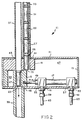
- FIG. 1 a sample changer 11 including a case 13. Disposed within case 13 are holder 15 slidably disposed in the case, two-way pneumatic drive 17 connected to and driving the holder, and spacing block 19 spacing the upper wall 21 of the case away from holder 15 so that the next lowest sample rotor 25 of sample rotors 23-33 can enter the case.
- block 19 in the apparatus of FIG. 1 is not absolutely necessary; instead, upper wall 21 could be disposed just above and in slidable contact with holder 15.
- Sample changer 11 further includes feed tube 35, eject tube 37 and insertion tube 39, each engaging or otherwise connected to a corresponding opening 41, 43 or 45 of case 13.
- Holder 15 is slidably disposed in interior chamber 47 of case 13, and is moved between a first position (shown in FIG. 1) and a second position (shown in FIG. 2) by drive 17.
- Drive 17 is typically provided with a piston 49, and is provided with two input ports 51 and 53 for receipt of compressed air or other fluid, each for moving that piston in one of the two directions shown in FIG. 2.
- application of compressed air at port 53 would result in sideways movement of holder 15 from the first position of FIG. 1 to the second position of FIG. 2.
- input of compressed air at port 51 would move holder 15 to the right as shown in FIGS.
- Case 13 is provided with respective openings 55 and 57 for ports 51 and 53.
- a respective connector 59 and 61 connects respective ports 51 and 53 to respective pneumatic lines 63 and 65.
- Case 13, holder 15 and block 19 can, for example, each be of aluminum.
- Tubes 35, 37 and 39 can, for example, each be of brass.
- Rotors 23-33 each holding a sample of solid material to be tested, are inserted into and stacked in feed tube 35. If holder 15 is in the first position of FIG. 1, then the lowest rotor 23 will enter compartment 67 of holder 15. Otherwise, the lowest rotor would enter block 19, but would be held above holder 15 by its edge 71 until drive 17 moves the holder to the first position. After the lowest or bottom rotor 23 has entered compartment 67 of holder 15, and when the spectrometer 111 or other device is ready to receive a sample for testing, compressed air from line 65 closes drive 17 to urge the holder leftwards to the second position of FIG. 2. In the position of FIG.
- rotor 23 would simply drop via opening 45 and insertion tube 39 into the spectrometer.
- compressed air from line 63 would close drive 17 to move holder 15 rightwards to the first position of FIG. 1 so that the next rotor 25 can enter compartment 67.
- rotor 15 is furthermore provided with bevelled or sloped indentation 73, which is more clearly shown in FIGS. 3 and 4, and slopes or inclines into compartment 67.
- spectrometer 111 When spectrometer 111 has finished testing rotor 23, it ejects that rotor using a blast of compressed air, as discussed above. That blast of ejection air closes the tested rotor to pass through insertion tube 39, compartment 69 and eject tube 37. For this reason, eject tube 37 and insertion tube 39 are aligned.
- the holder or slider 15 has two holes 67 and 69 through it, which are the same diameter as tubes 35, 37 and 39. In its rest or first position, these two holes are respectively positioned directly below the feed 29 and ejection 37 tubes. Feed tube 35, as discussed above, is filled with rotors, stacked one on top of the other. Due to gravity, the bottom rotor 23 will fall into hole 67 and slider 15. In order to insert a rotor into spectrometer 111, pneumatic pressure is applied to piston 49, closing the piston to push the slider away from it. This positions the rotor, which is in slider 15, over insert tube 39. Due to gravity, the rotor falls into the spectrometer.
- FIGS. 5A-5D A second embodiment of the present invention is shown in FIGS. 5A-5D in various positions and various stages of operation.
- This sample changer 75 is primarily differentiated from sample changer 11 of FIGS. 1-4 in that it includes a holder or slider 77 having only one compartment or hole 79 for receiving rotors 23-27.
- sample changer 75 includes a case 81 with an interior chamber 83, a spacing block 85, a feed tube 87, an eject tube 89 and an insertion tube 91.
- no drive such as drive 17 of FIGS. 1 and 2 is shown in FIGS. 5A-5D for simplicity, it will be appreciated that some such drive is needed to move slider 77 between its first position of FIGS. 5A and 5D and its second position of FIGS. 5B and 5C.
- insertion tube 91 of FIGS. 5A-5D is connected to, or is disposed at least partially within, a spectrometer or other testing device such as NMR spectrometer 111.
- slider 77 is being moved by a suitable mover or driver (not shown) controlled by a suitable pair of input ports having feed lines connected thereto (also not shown). Operation is preferably initiated in the position of FIG. 5A. Again, a plurality of rotors 23, 25, 27, etc. is inserted into feed tube 87 in a stack with the bottom rotor 23 entering bore 79 of slider 77. Slider 77 is then moved leftwards into its second position of FIG. 5B. In the position of FIG. 5B, gravity or other suitable force causes rotor 23 to drop through insertion tube 39 into the testing device for testing. As shown in FIG.
- slider 77 remains in its second position during ejection of rotor 23 from spectrometer 111 or other testing device. As described above, after spectrometer 111 has finished testing a rotor, it ejects that rotor with a blast of compressed air. Tested rotor 23 when ejected thereby is impelled through insertion tube 91, bore 79 and eject tube 89. Thereafter, as shown in FIG. 5D, slider 77 is moved rightward into its first position so that the next rotor 25 can drop into bore 79. The cycle of FIGS. 5A-5D is then repeated, this time with rotor 25 being tested.
- a pneumatic drive is shown as drive 17 in FIGS. 1 and 2, it should be understood that any sort of drive can be utilized with the present invention.
- drive 17 could be replaced with a piston or a rod having the appropriate detents to limit its movement between what would correspond to the first and second positions of the slider 15 or 77.
- a solenoid, a hydraulic actuator, a motor, or any other suitable moving or impelling device could be utilized to move slider 15 or 77 between its first or second positions.
- a pneumatic drive is preferred for this purpose, to take advantage of the compressed air used for insertion and ejection of rotors in NMR spectrometer 111.
- the compressed air used for insertion of a rotor in spectrometer 111 could also be provided to line 63, and the compressed air used for ejection of a rotor from the spectrometer could also be provided to line 65.
- positioning and movement of slider 15 could be coordinated with operation of spectrometer 111, resulting in fully automatic operation.
- a stack of rotors could be loaded into feed tube 27, spectrometer 111 could then be turned on, and the apparatus left to operate over the weekend with no human attendant required.
- sample changer 93 includes a cylindrical or drum-shaped case 95 containing a disk 97 provided with bores 99 and 101.
- Sample changer 93 further includes feed tube 103, eject tube 105, and insertion tube 107.
- Disk 97 is pivotably rotated within cylinder 95 between a first position as shown in FIG. 6 with bore 99 being disposed below feed tube 103, and a second position counterclockwise from the first position wherein bore 99 is disposed in alignment with eject tube 105 and insertion tube 107.
- Such movement is accomplished by suitable drive means (not shown), but which can be controlled via an electric or other line 109, a pair of pneumatic lines (not shown), or other suitable means.
- operation of the embodiment of FIG. 6 is similar to that of the embodiment if FIGS. 1-4.
- sample changer 11 (or for that matter, sample changer 75 or sample changer 93) is disposed atop cylinder 115 of spectrometer 111.
- Insertion tube 39 (or insertion tube 91, or insertion tube 107) is inserted into magnet chamber 113 via cylinder 115.
- Pneumatic lines 63 and 65 for control of drive 17 (or the corresponding drives of sample changer 75 or sample changer 93) are connected to spectrometer 111 for provision of compressed therefrom as described above, preferably.
- novel apparatus and method have been provided for repeated exchanging of similarly configured objects at a predetermined location.
- This apparatus and method can be used for sequentially inserting and removing solid samples to and from a device for testing such samples.
- a sample changer has been shown which can be used with an NMR spectrometer or other testing device which treats rotors or other holders for solid samples as if they were robust, not fragile devices.
- Utilizing the apparatus and method of the present invention it is possible to provide automatic feed and ejection of samples to and from a testing device, thereby permitting unattended automatic operation of that testing device for extended periods of time.
- the apparatus and method of the present invention provides rapid, easy, automatic changing of samples to and from a device that tests such samples.
Landscapes
- Physics & Mathematics (AREA)
- Condensed Matter Physics & Semiconductors (AREA)
- General Physics & Mathematics (AREA)
- Sampling And Sample Adjustment (AREA)
- Automatic Analysis And Handling Materials Therefor (AREA)
Applications Claiming Priority (2)
| Application Number | Priority Date | Filing Date | Title |
|---|---|---|---|
| US07/663,709 US5200702A (en) | 1991-03-04 | 1991-03-04 | Feed mechanism and method therefor |
| US663709 | 1996-06-14 |
Publications (2)
| Publication Number | Publication Date |
|---|---|
| EP0502444A2 true EP0502444A2 (de) | 1992-09-09 |
| EP0502444A3 EP0502444A3 (en) | 1993-02-24 |
Family
ID=24662972
Family Applications (1)
| Application Number | Title | Priority Date | Filing Date |
|---|---|---|---|
| EP19920103469 Withdrawn EP0502444A3 (en) | 1991-03-04 | 1992-02-28 | Feed mechanism and method therefor |
Country Status (2)
| Country | Link |
|---|---|
| US (1) | US5200702A (de) |
| EP (1) | EP0502444A3 (de) |
Cited By (3)
| Publication number | Priority date | Publication date | Assignee | Title |
|---|---|---|---|---|
| US7248050B2 (en) | 2004-06-18 | 2007-07-24 | Bruker Biospin Gmbh | NMR apparatus |
| GB2464807A (en) * | 2008-10-31 | 2010-05-05 | Bruker Biospin Gmbh | NMR MAS probe head with integral transport conduit for an MAS rotor |
| DE102008063703B3 (de) * | 2008-12-19 | 2010-06-17 | Bruker Biospin Ag | Automatische Transportvorrichtung für NMR-Messproben, Kryomagnetsystem mit automatischer Transportvorrichtung, Transportbehälter für automatische Transportvorrichtung und Verfahren zum Befördern einer NMR-Messprobe |
Families Citing this family (8)
| Publication number | Priority date | Publication date | Assignee | Title |
|---|---|---|---|---|
| DE4413135C2 (de) * | 1994-04-19 | 1997-03-27 | Boellhoff Gmbh | Vereinzelungsvorrichtung für Befestigungsmittel, insbesondere Schrauben |
| US5705928A (en) * | 1996-06-14 | 1998-01-06 | Varian Associates, Inc. | Sample delivery system used in chemical analysis methods which employs pressurized gas for sample conveyance |
| US5754048A (en) * | 1996-07-17 | 1998-05-19 | Bruker Instruments, Inc. | Method and apparatus for precisely controlling the periodic motion of an object |
| US6937020B2 (en) * | 2003-02-04 | 2005-08-30 | The University Of Kansas | Solid-state nuclear magnetic resonance probe |
| US6768305B1 (en) | 2003-09-26 | 2004-07-27 | Varian, Inc. | Temperature controlled sample changer for NMR analysis |
| US7019526B2 (en) * | 2004-05-24 | 2006-03-28 | Varian, Inc. | Sample catcher for NMR apparatus and method utilizing thereof |
| DE102006048955B4 (de) * | 2006-10-17 | 2010-12-16 | Bruker Biospin Gmbh | Vollautomatische MAS-NMR-Apparatur |
| JP6876471B2 (ja) * | 2017-03-07 | 2021-05-26 | 日本電子株式会社 | Nmr試料管導入回収装置、及び、nmr試料管導入回収方法 |
Family Cites Families (18)
| Publication number | Priority date | Publication date | Assignee | Title |
|---|---|---|---|---|
| US3194389A (en) * | 1963-10-16 | 1965-07-13 | Gen Electric | Lamp bulb feeding mechanism |
| US3247980A (en) * | 1964-06-02 | 1966-04-26 | Michaigan Tool Company | Means for transporting workpieces to and from a work station |
| US3512078A (en) * | 1967-06-12 | 1970-05-12 | Varian Associates | Gyromagnetic resonance spectrometer employing air pressure for ejecting samples from the magnet |
| US3798422A (en) * | 1970-07-20 | 1974-03-19 | Dennison Mfg Co | Ticket reader |
| DE2546245C3 (de) * | 1975-10-15 | 1978-09-28 | Dr. Carl Hahn Gmbh, 4000 Duesseldorf | Vorrichtung zum Überführen von länglichen Gegenständen von einer ersten Bearbeitungsstation zu einer zweiten Bearbeitungsstation |
| US4091323A (en) * | 1976-10-06 | 1978-05-23 | Eli Lilly And Company | Automated sample changer for nuclear magnetic resonance spectrometer |
| US4369570A (en) * | 1978-07-10 | 1983-01-25 | General Electric Company | Apparatus for inserting insulating disc in cell container |
| US4343587A (en) * | 1979-02-05 | 1982-08-10 | Aidlin Automation, Inc. | Machine for horizontal transportation of containers |
| US4581583A (en) * | 1984-02-29 | 1986-04-08 | General Electric Company | Apparatus for sample selecting, placing and retrieving for use with NMR spectrometers |
| US4654592A (en) * | 1985-01-14 | 1987-03-31 | Varian Associates, Inc. | Concurrent NMR analysis of multiple samples |
| JPS6263846A (ja) * | 1985-09-13 | 1987-03-20 | Hitachi Ltd | 核磁気共鳴装置用試料交換機 |
| US4765793A (en) * | 1986-02-03 | 1988-08-23 | Proconics International, Inc. | Apparatus for aligning circular objects |
| DE3729819A1 (de) * | 1987-09-05 | 1989-03-16 | Spectrospin Ag | Magnetanordnung fuer nmr-spektrometer |
| US4859949A (en) * | 1988-01-26 | 1989-08-22 | Siemens Aktiengesellschaft | Magnetic resonance spectroscopy apparatus |
| US4832555A (en) * | 1988-03-18 | 1989-05-23 | Gordon John H | Gasket holding and feeding magazine |
| JPH01240227A (ja) * | 1988-03-22 | 1989-09-25 | Mitsubishi Pencil Co Ltd | 部品供給装置 |
| DE3818039A1 (de) * | 1988-05-27 | 1989-11-30 | Bruker Analytische Messtechnik | Nmr-spektrometer mit einem probenwechsler |
| US5104277A (en) * | 1989-04-06 | 1992-04-14 | Hewlett-Packard Company | Method and apparatus for automatically changing printed circuit board test fixtures |
-
1991
- 1991-03-04 US US07/663,709 patent/US5200702A/en not_active Expired - Lifetime
-
1992
- 1992-02-28 EP EP19920103469 patent/EP0502444A3/en not_active Withdrawn
Cited By (6)
| Publication number | Priority date | Publication date | Assignee | Title |
|---|---|---|---|---|
| US7248050B2 (en) | 2004-06-18 | 2007-07-24 | Bruker Biospin Gmbh | NMR apparatus |
| GB2464807A (en) * | 2008-10-31 | 2010-05-05 | Bruker Biospin Gmbh | NMR MAS probe head with integral transport conduit for an MAS rotor |
| US8212559B2 (en) | 2008-10-31 | 2012-07-03 | Bruker Biospin Gmbh | NMR-MAS probehead with integral transport conduit for an MAS-rotor |
| GB2464807B (en) * | 2008-10-31 | 2012-12-26 | Bruker Biospin Gmbh | NMR-MAS probe head with integral transport conduit for an MAS-rotor |
| DE102008063703B3 (de) * | 2008-12-19 | 2010-06-17 | Bruker Biospin Ag | Automatische Transportvorrichtung für NMR-Messproben, Kryomagnetsystem mit automatischer Transportvorrichtung, Transportbehälter für automatische Transportvorrichtung und Verfahren zum Befördern einer NMR-Messprobe |
| US8217655B2 (en) | 2008-12-19 | 2012-07-10 | Bruker Biospin Ag | Automated transport device for NMR measuring samples, cryo-magnetic system with automated transport device, transport container for an automated transport device and method for conveying an NMR measuring sample |
Also Published As
| Publication number | Publication date |
|---|---|
| US5200702A (en) | 1993-04-06 |
| EP0502444A3 (en) | 1993-02-24 |
Similar Documents
| Publication | Publication Date | Title |
|---|---|---|
| US8734719B2 (en) | Parts supply device, sample analyzing device, parts supply method | |
| JP5997706B2 (ja) | 空気圧式メールシステムと、研究所自動化システムへバイオ製品容器を供給するシステムとの間にあるインターフェース装置 | |
| US5200702A (en) | Feed mechanism and method therefor | |
| US3985507A (en) | Automatic test sample handling system | |
| EP1353183B1 (de) | Vorrichtung zur Probenvorbehandlung | |
| US6255614B1 (en) | Specimen-container transfer apparatus | |
| US5146166A (en) | Method and apparatus for enhancing sample analysis rate in magnetic resonance spectroscopy | |
| JP3331253B2 (ja) | 自動分析装置の試験片取出装置 | |
| US7549557B2 (en) | Device for separating objects | |
| US20030175156A1 (en) | Automatic crucible and sample loading system and method | |
| US5237276A (en) | Feed mechanism and method therefor | |
| JP6775580B2 (ja) | 生体液体サンプルを撹拌し収集するための装置 | |
| CN102282470A (zh) | 用于生物材料容器的等分设备 | |
| JP7316763B2 (ja) | 分析、特に医学分析の自動実行のための自動デバイス | |
| US6168002B1 (en) | Control system for use with semiconductor device transporting and handling apparatus | |
| JP6525520B2 (ja) | 球状又は円筒状物体を分離する装置 | |
| JP6824980B2 (ja) | ソートに適した生体液体サンプルを撹拌し収集するための装置 | |
| CN208868936U (zh) | 试剂盒运送装置 | |
| JPH0727017B2 (ja) | 試料交換器を備えたnmr―分光計 | |
| US20100307109A1 (en) | Apparatus for closing biological material containers | |
| US12247992B2 (en) | Analyzer and analyzer control method | |
| EP3346276B1 (de) | Automatische behälterverarbeitungsvorrichtung | |
| US5904285A (en) | Nail transfer apparatus | |
| JP7857147B2 (ja) | 自動分析装置および自動分析方法 | |
| JP2017096964A (ja) | 検体処理システム |
Legal Events
| Date | Code | Title | Description |
|---|---|---|---|
| PUAI | Public reference made under article 153(3) epc to a published international application that has entered the european phase |
Free format text: ORIGINAL CODE: 0009012 |
|
| AK | Designated contracting states |
Kind code of ref document: A2 Designated state(s): CH DE FR GB LI |
|
| PUAL | Search report despatched |
Free format text: ORIGINAL CODE: 0009013 |
|
| AK | Designated contracting states |
Kind code of ref document: A3 Designated state(s): CH DE FR GB LI |
|
| 17P | Request for examination filed |
Effective date: 19930802 |
|
| STAA | Information on the status of an ep patent application or granted ep patent |
Free format text: STATUS: THE APPLICATION IS DEEMED TO BE WITHDRAWN |
|
| 18D | Application deemed to be withdrawn |
Effective date: 19950901 |