EP0502665A1 - Filmtransport- und Leitsystem - Google Patents
Filmtransport- und Leitsystem Download PDFInfo
- Publication number
- EP0502665A1 EP0502665A1 EP92301715A EP92301715A EP0502665A1 EP 0502665 A1 EP0502665 A1 EP 0502665A1 EP 92301715 A EP92301715 A EP 92301715A EP 92301715 A EP92301715 A EP 92301715A EP 0502665 A1 EP0502665 A1 EP 0502665A1
- Authority
- EP
- European Patent Office
- Prior art keywords
- film
- guide
- core
- exit
- take
- Prior art date
- Legal status (The legal status is an assumption and is not a legal conclusion. Google has not performed a legal analysis and makes no representation as to the accuracy of the status listed.)
- Withdrawn
Links
Images


Classifications
-
- G—PHYSICS
- G03—PHOTOGRAPHY; CINEMATOGRAPHY; ANALOGOUS TECHNIQUES USING WAVES OTHER THAN OPTICAL WAVES; ELECTROGRAPHY; HOLOGRAPHY
- G03D—APPARATUS FOR PROCESSING EXPOSED PHOTOGRAPHIC MATERIALS; ACCESSORIES THEREFOR
- G03D13/00—Processing apparatus or accessories therefor, not covered by groups G11B3/00 - G11B11/00
- G03D13/003—Film feed or extraction in development apparatus
Definitions
- This invention relates to photographic film processing apparatus, and more particularly to a system for transporting film through the apparatus.
- Photographic film processing is accomplished by immersing undeveloped film in a number of liquid solutions in a pre-determined order. These steps include developing, bleaching, fixing, rinsing, etc., and it has long been conventional to automate film processing by providing a series of adjacent open-topped tanks in a housing through which long strips of film are sequentially transported by a film transport system.
- United States Patent no. 4,929,976 assigned to the Assignee of the present invention, discloses a film transport system which accommodates the use of a thin, flexible film carrier card with a simplified dual serpentine belt arrangement.
- the disclosure of U. S. Patent No. 4,929,976 is incorporated herein by reference, as if fully set forth.
- a prior art film processing apparatus 1 of the type shown in U. S. Patent No. 4,929,976 includes an apparatus exit 2 and a take-up member 3 consisting of a core 4 and two reel sides 5a and 5b.
- a film carrier card In current practice, undeveloped film is attached to a film carrier card and introduced into apparatus 1 at its other end (not shown).
- the carrier card transports the film through the various tanks of apparatus 1 to exit 2, whereupon an alarm buzzer 6 sounds alerting technician 7 that film carrier card 8 and attached film 9 are about to exit the apparatus 1.
- the present invention provides an improved system for transporting film along a predetermined path through an apparatus exit to a take-up member.
- the system includes cutting means located at substantially the apparatus exit for cutting a film carrier from the film before reaching the take-up member.
- the take-up member consists essentially of a cylindrical core without lateral guide walls associated with the core.
- Non-rotating guide means located at substantially the apparatus exit are provided to guide the film onto the core.
- the guide means has a plurality of guide walls for directing film transported through the exit to the core.
- Carrier guide means located at substantially the apparatus exit is provided for guiding the carrier away from the film after cutting by the cutting means.
- film processing apparatus 100 includes a housing 102 and a plurality of processing tanks 104.
- dual serpentine belts 106 transport film 108 through tanks 104 by way of a carrier card 110.
- a second film 112 is shown being transported through apparatus exit 114.
- cutting means 116 cuts carrier card 118 from film 112, and guide means 120 guides the remainder of the film onto take-up member 122. As shown, carrier card 118 is guided away from film 112 after cutting by the cutting means.
- cutting means 116 includes a solenoid 130 which is activated to extend arm 132 after a carrier card has passed through exit slot 134.
- Arm 132 contacts rocker arm 135, which is pivotally mounted to the apparatus by way of a shaft 136 in saddle member 138.
- Substantially identical shaft and saddle members are located on the opposite of rocker arm 135, but are omitted from the Figures for clarity.
- An end 136 of rocker arm 135 contacts a top surface 138 of a cutter ram 140.
- Cutter ram 140 is mounted for sliding movement with respect to cutter end plate 142, which is fixed to the apparatus.
- a spring 144 has one end 146 connected to cutter ram 140 and the other end 148 connected to cutter end plate 142. Spring 144 biases cutter ram 140 to the upward position in contact with rocker arm 135 shown in figure 6. Knife blade 150 is attached to a lower end 152 of cutter ram 140. A bottom exit cutter ramp 152 includes a slot 154 directly below blade 150. A top exit cutter ramp 155 ( Figure 5) is also provided. Exit 134 is located in exit cover plate 156, which carries a take-up spool 158.
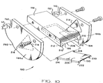
- Guide means 120 primarily includes a guide assembly 180 located at substantially the apparatus exit 134.
- Guide assembly 180 includes a plurality of guide walls for directing film transported through the exit to take-up member 122.
- Guide assembly 180 is pivotally mounted to exit cover plate 156 by way of guide hinge pins 182 riding in saddle members 184. Saddle members 184 are connected to exit cover plate 156.
- Guide assembly 180 is constructed of essentially four pieces: Lateral plates 186a and 186b, upper plate 188 and a film guide ramp 190. Pins 182 extend from end portions 192 of lateral plates 186a and 186b.
- Lateral plates 186a and 186b are fixed to upper plate 188, such that lateral guide walls 194 on the inside surfaces of lateral members 186a and 186b depend from an upper guide wall 196 on the bottom surface of upper plate 188.
- Lateral guide walls 194 are parallel planar surfaces spaced apart approximately the distance of the lateral edges 198 of the film for which the apparatus is utilized.
- Upper guide wall 196 has an end portion 200 which contacts a rotating cylindrical surface 202 of core 204 when core 204 is empty.
- End portion 202 includes a channel 206 for the passage of adhesive tape 208 applied to cylindrical surface 202 therethrough. Surfaces 210 on two sides 212 of channel 206 contact core cylindrical surface 202 when the core is empty and side portions of the film as the core is being wound with film.
- Film guide ramp 190 is pivotally mounted within guide assembly 180 by way of ears 214 which engage holes 216 in lateral guide walls 194.
- Guide ramp 190 is free to pivot within triangular relief surfaces 218 formed in lateral guide walls 194.
- a channel 220 is formed in a bottom surface 222 of guide ramp 190.
- Lower guide wall 224 is the top surface of ramp 190
- Take-up member 122 includes take-up main arm 240 which extends from apparatus 100. As best shown in Figure 7, a drive chain 242 drives a belt 244, which in turn drives a shaft 246 in conventional fashion. Take-up bearing post 248 extends from main arm 240, with drive shaft 246 rotatably mounted therein. A core spindle 250 is connected to drive shaft 246, and is configured to accept core 204 for co-rotating engagement.
- Carrier guide means includes curved walls 260 located on lateral plates 186a and 186b. Curved walls 260 are spaced more narrowly than the width of a film carrier card, such that an emerging film carrier card is guided downwardly and away from the film as it exits and after cutting by the cutting means 116.
- the present invention eliminates the need for an operating technician to wait for a film carrier card and film to come out the exit of the processing apparatus and then cut the carrier card from the film and engage the film with a take-up reel. Instead, the film carrier card is automatically cut from the film, and then the film automatically winds itself onto take-up member 122.
- the need for reel sides is eliminated by providing lateral guide walls associated with the apparatus itself, contrasted with the rotating reel guides attached to the core used in the past.
- cutter ram 140 is biased to its upward position by way of spring 144, until solenoid 130 is actuated to push cutter ram 140 downwardly by way of rocker arm 135. Blade 150 is pushed into slot 154, thereby severing any film in its path. Solenoid 130 is actuated immediately after a film carrier card is passed through the exit.
- the film carrier card is severed from the film, it is pushed downwardly by curved walls 260 on guide assembly 180.
- the free end of the film is guided between lateral guide walls 194, directed upwardly by lower guide wall 224 to the rotating cylindrical surface 202 of core 204.
- Guide assembly 180 being pivotally mounted to the apparatus, pivots upwardly to accommodate the increasing mass of film.
- the guide ramp 190 being pivotally mounted within guide assembly 180 also pivots to accommodate the increasing mass of film and to maintain tight winding on core 204.
Landscapes
- Physics & Mathematics (AREA)
- General Physics & Mathematics (AREA)
- Photographic Processing Devices Using Wet Methods (AREA)
Applications Claiming Priority (2)
| Application Number | Priority Date | Filing Date | Title |
|---|---|---|---|
| US66428291A | 1991-03-04 | 1991-03-04 | |
| US664282 | 1991-03-04 |
Publications (1)
| Publication Number | Publication Date |
|---|---|
| EP0502665A1 true EP0502665A1 (de) | 1992-09-09 |
Family
ID=24665377
Family Applications (1)
| Application Number | Title | Priority Date | Filing Date |
|---|---|---|---|
| EP92301715A Withdrawn EP0502665A1 (de) | 1991-03-04 | 1992-02-28 | Filmtransport- und Leitsystem |
Country Status (1)
| Country | Link |
|---|---|
| EP (1) | EP0502665A1 (de) |
Cited By (3)
| Publication number | Priority date | Publication date | Assignee | Title |
|---|---|---|---|---|
| EP0611993A1 (de) * | 1993-02-16 | 1994-08-24 | Noritsu Koki Co., Ltd. | Entwicklungsgerät für fotografischen Film |
| EP0623850A1 (de) * | 1993-05-03 | 1994-11-09 | Eastman Kodak Company | Verfahren und Vorrichtung zur Behandlung photographischer Filmstreifen beim Ausgang aus einem Filmbehandlungsgerät |
| EP0689093B1 (de) * | 1994-06-20 | 2001-11-21 | Noritsu Koki Co., Ltd. | Filmwickler |
Citations (4)
| Publication number | Priority date | Publication date | Assignee | Title |
|---|---|---|---|---|
| GB1479962A (en) * | 1975-03-24 | 1977-07-13 | Secr Defence | Tape winding device |
| DD144128A1 (de) * | 1979-05-31 | 1980-09-24 | Helmut Kohl | Vorrichtung zum richten von spulen |
| DE3538082A1 (de) * | 1984-10-25 | 1986-04-30 | Fuji Photo Film Co., Ltd., Minami-Ashigara, Kanagawa | Einrichtung zum automatischen aufwickeln von fotopapier |
| US4929976A (en) * | 1989-03-15 | 1990-05-29 | Jamieson Film Company | Film transport system |
-
1992
- 1992-02-28 EP EP92301715A patent/EP0502665A1/de not_active Withdrawn
Patent Citations (4)
| Publication number | Priority date | Publication date | Assignee | Title |
|---|---|---|---|---|
| GB1479962A (en) * | 1975-03-24 | 1977-07-13 | Secr Defence | Tape winding device |
| DD144128A1 (de) * | 1979-05-31 | 1980-09-24 | Helmut Kohl | Vorrichtung zum richten von spulen |
| DE3538082A1 (de) * | 1984-10-25 | 1986-04-30 | Fuji Photo Film Co., Ltd., Minami-Ashigara, Kanagawa | Einrichtung zum automatischen aufwickeln von fotopapier |
| US4929976A (en) * | 1989-03-15 | 1990-05-29 | Jamieson Film Company | Film transport system |
Non-Patent Citations (3)
| Title |
|---|
| PATENT ABSTRACTS OF JAPAN vol. 4, no. 51 (P-007)17 April 1980 & JP-A-55 022 730 ( YOSHIHISA YAMAGUCHI ) 18 February 1980 * |
| PATENT ABSTRACTS OF JAPAN vol. 6, no. 108 (P-123)(986) 18 June 1982 & JP-A-57 040 233 ( CANON ) 5 March 1982 * |
| PATENT ABSTRACTS OF JAPAN vol. 9, no. 55 (M-362)(1778) 9 March 1985 & JP-A-59 190 149 ( FUJI XEROX ) 27 October 1984 * |
Cited By (5)
| Publication number | Priority date | Publication date | Assignee | Title |
|---|---|---|---|---|
| EP0611993A1 (de) * | 1993-02-16 | 1994-08-24 | Noritsu Koki Co., Ltd. | Entwicklungsgerät für fotografischen Film |
| US5692228A (en) * | 1993-02-16 | 1997-11-25 | Noritsu Koki Co., Ltd. | Photographic film developing apparatus |
| CN1040372C (zh) * | 1993-02-16 | 1998-10-21 | 诺日士钢机株式会社 | 照像胶片显影装置 |
| EP0623850A1 (de) * | 1993-05-03 | 1994-11-09 | Eastman Kodak Company | Verfahren und Vorrichtung zur Behandlung photographischer Filmstreifen beim Ausgang aus einem Filmbehandlungsgerät |
| EP0689093B1 (de) * | 1994-06-20 | 2001-11-21 | Noritsu Koki Co., Ltd. | Filmwickler |
Similar Documents
| Publication | Publication Date | Title |
|---|---|---|
| EP0251338A2 (de) | Filmsammler für Entwicklungsmaschine | |
| US4297930A (en) | Strip cutter having rotatable cutting blade and strip deflecting means | |
| US3292471A (en) | Roll feed attachment for duplicating apparatus | |
| US3906966A (en) | Film handling device | |
| US4060210A (en) | Take-up spools | |
| EP0502665A1 (de) | Filmtransport- und Leitsystem | |
| US4894674A (en) | Daylight bulk film loading system | |
| EP0421493A2 (de) | Magazin für Filmzuführvorrichtung | |
| JPH0214693B2 (de) | ||
| JPH07114109A (ja) | 感光材料の切断装置 | |
| US3955779A (en) | Cartridge with removable take-up sub-cartridge | |
| JPH06115775A (ja) | 使用者の機械へ等間隔の切欠きを有する帯を連続的に供給するための方法 | |
| US4949114A (en) | Device for introducing the free end of a photographic film to be developed, unwound from a reel, into a film developing unit | |
| JPH0214694B2 (de) | ||
| US5015089A (en) | Leader assembly and method | |
| US4843412A (en) | Film supplying apparatus | |
| EP0677785B1 (de) | Automatische Filmentwicklungsmaschine mit einer Filmaufwickelvorrichtung | |
| US4064677A (en) | Microfilm inserter | |
| EP0562675B1 (de) | Guillotine mit flexiblem Scherblatt | |
| GB2265992A (en) | Film feeding apparatus | |
| KR100208115B1 (ko) | 필름 와인더 | |
| JP2943561B2 (ja) | フィルム自動巻替装置 | |
| US5979034A (en) | Method of manufacturing a tape cartridge and apparatus for forming a marking hole for use in the method | |
| US3363959A (en) | Roll feed attachment for duplicating apparatus | |
| US5963757A (en) | System for processing a photosensitive material |
Legal Events
| Date | Code | Title | Description |
|---|---|---|---|
| PUAI | Public reference made under article 153(3) epc to a published international application that has entered the european phase |
Free format text: ORIGINAL CODE: 0009012 |
|
| AK | Designated contracting states |
Kind code of ref document: A1 Designated state(s): CH DE ES FR GB IT LI NL SE |
|
| 17P | Request for examination filed |
Effective date: 19930303 |
|
| 17Q | First examination report despatched |
Effective date: 19941125 |
|
| 18D | Application deemed to be withdrawn |
Effective date: 19950406 |