EP0502736A2 - Système modulaire de cloison - Google Patents
Système modulaire de cloison Download PDFInfo
- Publication number
- EP0502736A2 EP0502736A2 EP92301905A EP92301905A EP0502736A2 EP 0502736 A2 EP0502736 A2 EP 0502736A2 EP 92301905 A EP92301905 A EP 92301905A EP 92301905 A EP92301905 A EP 92301905A EP 0502736 A2 EP0502736 A2 EP 0502736A2
- Authority
- EP
- European Patent Office
- Prior art keywords
- panel
- frame members
- panels
- parallel
- partition
- Prior art date
- Legal status (The legal status is an assumption and is not a legal conclusion. Google has not performed a legal analysis and makes no representation as to the accuracy of the status listed.)
- Withdrawn
Links
Images


Classifications
-
- E—FIXED CONSTRUCTIONS
- E04—BUILDING
- E04C—STRUCTURAL ELEMENTS; BUILDING MATERIALS
- E04C2/00—Building elements of relatively thin form for the construction of parts of buildings, e.g. sheet materials, slabs, or panels
- E04C2/30—Building elements of relatively thin form for the construction of parts of buildings, e.g. sheet materials, slabs, or panels characterised by the shape or structure
- E04C2/34—Building elements of relatively thin form for the construction of parts of buildings, e.g. sheet materials, slabs, or panels characterised by the shape or structure composed of two or more spaced sheet-like parts
- E04C2/36—Building elements of relatively thin form for the construction of parts of buildings, e.g. sheet materials, slabs, or panels characterised by the shape or structure composed of two or more spaced sheet-like parts spaced apart by transversely-placed strip material, e.g. honeycomb panels
-
- E—FIXED CONSTRUCTIONS
- E04—BUILDING
- E04B—GENERAL BUILDING CONSTRUCTIONS; WALLS, e.g. PARTITIONS; ROOFS; FLOORS; CEILINGS; INSULATION OR OTHER PROTECTION OF BUILDINGS
- E04B2/00—Walls, e.g. partitions, for buildings; Wall construction with regard to insulation; Connections specially adapted to walls
- E04B2/74—Removable non-load-bearing partitions; Partitions with a free upper edge
- E04B2/7407—Removable non-load-bearing partitions; Partitions with a free upper edge assembled using frames with infill panels or coverings only; made-up of panels and a support structure incorporating posts
- E04B2/7416—Removable non-load-bearing partitions; Partitions with a free upper edge assembled using frames with infill panels or coverings only; made-up of panels and a support structure incorporating posts with free upper edge, e.g. for use as office space dividers
- E04B2/7422—Removable non-load-bearing partitions; Partitions with a free upper edge assembled using frames with infill panels or coverings only; made-up of panels and a support structure incorporating posts with free upper edge, e.g. for use as office space dividers with separate framed panels without intermediary support posts
- E04B2/7425—Details of connection of panels
Definitions
- the present invention relates generally to partition systems for partitioning a room into a number of smaller cubicles or divisions.
- Partitioning systems are used for numberof purposes, not only to divide a room into smaller chambers but also to create the impression of a room or a plurality of rooms at exhibitions, and to divide offices into different working areas.
- screen- type partition systems are frequently used comprising rigid panels secured on uprights having feet which can rest on the finished surface of the office floor without damage thereby allowing the screen to be moved from one position to another as circumstances change.
- partitioning systems which are largely based on uprights spanned by relatively insubstantial, often flexible screens are used. Both of these partitioning systems traditionally occupy less than the full height of the room and offer a temporary division which, by its nature, gives a sense of impermanence to the division thus achieved.
- a wooden framework of timber elements or studs is constructed and then covered with a cladding of rigid material such as plaster board which may further be provided with a skim coat of plaster to provide a smooth uniform finish spanning the junctions between adjacent boards, or may be dry-lined with lining paper and painted or further wallpapered to produce an impression of a permanent structural wall.
- the present invention seeks to provide a partitioning system which will offer considerable advantages of economy and speed of installation and nevertheless give a satisfactory impression of permanence whilst, in fact, being dismantleable and reusable.
- a modular partition system for a display stand or a room divider having a plurality of panels, in which each panel is composed of two cladding layers of rigid impact-resistant material spaced by an internal framework of frame members, one lateral edge of a panel having a frame member projecting beyond the edges of the cladding layers whilst at an opposite parallel edge of the panel the cladding layers project as parallel flanges beyond the frame to form a complementary cooperating channel shaped to receive the projecting frame member of an adjacent such panel whereby to interlock the two adjacent panels together.
- a plurality of floor plates comprising a laminar base element having an elongate ridge upstanding therefrom.
- At least one panel is provided with a prepared opening in the said two cladding layers, the edges of the opening being defined by elongate filler members, covering the space between the two spaced parallel cladding layers.
- Typical such openings may be an archway, a doorway or a window, and in the case of a door or window opening it is preferred that the said one panel is provided with a closure member hingedly attached to the panel along one edge of the said opening.
- At least one edge of at least one panel may be fitted with decorative trimming elements such as skirting board, architrave, picture rail or the like, and these may be fitted in position on the panel prior to the location of the panel in its finished position.
- decorative trimming elements such as skirting board, architrave, picture rail or the like
- the present invention thus provides means by which prefabricated panels having all the necessary architectural features such as skirting board, architrave, doors etc can be completed at the factory and installed in position on site quickly and easily by simple operations requiring relatively little disturbance to the existing structure.
- the modular partition system of the present invention further includes a plurality of elongate connector elements, in which the upper edge of each panel is provided with projecting parallel flanges defining an upwardly open channel by positioning the frame members inwardly of the edges of the said cladding layers, and the said elongate connector elements are attachable to the frame members to secure adjacent panels together.
- the channels defined at the edge or edges of the panels have a depth at least as great as their width such that adjacent panels can be fitted together at an angle to one another upon removal of one of the channel-defining flanges.
- the cooperating projecting frame element may also require some modification to its shape prior to installation, and it is preferred for this purpose that the frame members be made from a suitable material which can be readily worked using hand tools, such as timber, medium density fibre board or the like.
- the surface layers themselves be made from layers of medium density fibre board which has the required characteristics of strength and rigidity whilst nevertheless offering a sufficiently hard surface finish to allow the panels to be decorated, once installed, without the need for any further surface finishing work such as interlining with lining paper or skimming with gypsum and plaster, as has been necessary with previously known room dividing partitions constructed in situ.
- the present invention also comprehends a panel for a modular partitioning system comprising two parallel surface layers of impact-resistant laminar material held together in parallel spaced planes by a framework one member of which projects from one edge of the panel beyond the edges of the surface layers, and another member of which extends parallel to but inwardly of the edges of the surface layers whereby to define a channel for receiving a projecting frame member of another such panel so as to locate the panels in a common plane.
- the projecting frame member preferably extends substantially wholly along the edge of the panel to define a projecting tongue.
- the frame members and the surface layers may be made of the same material, namely medium density fibre board or other suitable material.
- the space between the surface layers defined by the adjacent frame members may further be filled with an insulation material acting to improve the thermal and/or acoustic insulation offered by the partition when erected.
- the panels may be located in place simply by their own weight, although it is preferred that some form of fixing to secure the panels together and to the floor plate may be employed. Fixing by means of adhesive may be utilised where a relatively permanent partition is envisaged although it is entirely within the scope of the present invention that adjacent panels may be secured together merely by fixing elements such as pins or screws which allow for ready removal and dismantling of the partition system to remove or reposition it at some later date.
- the present invention also comprehends a method of making a partitioning panel comprising the steps of positioning a plurality of frame members on a jig having means for locating the frame members in predetermined positions, securing the frame members together to form a supporting framework outlined by first and second parallel side frame members and third and fourth parallel and frame members extending transversely of the side frame members, positioning a first cladding layer over the framework such that first and second parallel edges of the first cladding layer lie parallel to but offset from the first and second side frame members with the first side frame members lying within the boundary of the first cladding layer and the second side frame member projecting beyond the boundary of the first cladding layer, and securing the said first cladding layer to the supporting framework in that position.
- the method of the present invention further comprises the steps of removing the partly-finished panel from the jig, inverting it and positioning a second cladding layer over the supporting framework in register with the first cladding layer, and fixing the second cladding layer to the said supporting framework.
- the present invention further comprehends a method of forming a partitioning wall comprising the steps of making a plurality of partition panels by the method defined hereinabove, positioning a floor plate having an upstanding ridge along the intended line of partition, and fitting one or a plurality of partition panels over the ridge locating and fixing the panel or panels in position.
- Figure 1 comprises a partition panel generally indicated 11 comprising two cladding layers 12, 13 of rigid medium density fibre board spaced by an internal framework comprising a plurality of upright frame members 14 (any one of which is visible in Figure 1) and a plurality of horizontal frame members 15, 16 of which the former is an upper horizontal frame member and the latter is a lower horizontal frame member.
- Figure 1a a illustrates a typical example of the structure of frame members to define the framework. In Figure 1a it can be seen that between the upper and lower frame members, 15, 16 there are typically three horizontal frame members 17,18,19 while the vertical frame member 14 is typically one of four upright frame members including outline frame members 20, 22 and inner frame member 21.
- the upright frame members, 20, 22 are spaced by the same overall distance as the width of the layer defining the surface layer 12 or 13, but as can be seen in Figure 1a the framework as a whole is offset laterally from the panels 12, 13 by a distance corresponding to the width of the frame members, that is the spacing between the cladding layers 12, 13.
- the upper and lower frame members 15,16 are spaced by a distance less than the height of the cladding layers 12, 13 so as to define, as can be seen in Figure 1a, upper and lower channels 23, 24 respectively.
- the projecting frame member 22 defines an elongate tongue whilst, at the opposite edge, the inset frame member 20 defines, with the overlapping flange edges of the layers 12, 13 a vertical channel 25.
- the partition panel 11 has a tongue 22 along one upright edge and channels 23, 24, 25 along the two parallel upper and lower edges and the upright edge opposite that defined by the tongue 22.
- the interior of a panel may be filled with insulating material (not shown) of any known type.
- the partition assembly also includes as shown in Figure 1 a floor plate generally indicated 26 having a width significantly greater than the width of the panel 11 itself, for example two or three times this width. Projecting up from the floor plate 26 is an elongate ridge 27 having a height and a width such as to match the depth and width of the channel 24 in the lower edge of the panel 11.
- the line of the partition can be defined by positioning a floor plate such as the plate 26 along the floor and, if required, fixing this to the floor, for example, by adhesive or fixing elements such as nails or screws.
- the position of the partition against a side wall of the room can be marked and located by a wall batten 28 secured to the wall in any known way, such as by masonry nails or screws suitably plugged to the walls, and the thickness and width of the batten 28 is chosen such as to match the depth and width of the channel 25 in the edge of the panel 11. Installation of the panel 11 is then simply a matter of dropping the panel over the ridge 27 and sliding it along towards the batten 28 until this is engaged within the channel 25.
- the panel 11 can be secured in place by pins, staples or adhesive if required.
- Depending on the length of partition wall to be constructed further such panels may be fitted over the ridge 27 and displaced until their vertical grooves 25 interlock with the vertical tongue 22 of the next adjacent panel.
- partition wall is to span to existing walls of a room it is unlikely that the length of partition wall required will be an integral multiple of the modular panel dimensions and, accordingly as can be seen in Figure 4, a final filler panel is required to make up the difference between the overall partition length and the nearest multiple of the modular partition width.
- the height of the panel may be sufficient to span the entire height of the room, or alternatively, further panels may be positioned over the panel 11 to an appropriate height.
- the upper edge of the panel 11 may be trimmed with a suitable architrave moulding structure such as that illustrated in Figure 1 comprising two moulding strips 29, 30 joined at their upper edges by a capping strip 31.
- the height of the moulding strips 29 is such that the capping can be fitted over the upper edge of a panel 11 allowing this to be fitted in position over the ridge 27 of the floor plate 26, and once the panel 11 is positioned, can be lifted slightly so that the capping 31 engages the ceiling whilst the moulding strips 29, 30 are suspended on either side of the upper flanges defined by the cladding layers 12, 13. This is possible providing the height of the moulding strips 29, 30 is sufficiently greater than the height of the ridge 27.
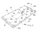
- FIG. 2 illustrates a forming jig by which modular panels in accordance with the present invention may be made.
- This jig comprises a bed 32 having, projecting therefrom, a plurality of pairs of pegs arranged in pairs in three rows 33, 34 and 35, the pairs of pegs in each of the rows 33, 34, 35 being identified with the subscripts a, b, c, d and e.
- the uprights 14, 21, 22 are positioned between adjacent rows of pegs 35, 34, 33 whilst the upright 20 is positioned against the row of pegs 36 and a spacer block 37 then located against it.
- Horizontal upper and lower frame members 15, 16 are then positioned against the ends of the uprights and secured in position by adhesive and/or pins or staples, and further horizontal frame members 17,18, 19 positioned spanning the uprights 20, 14, 21, 22.
- a cladding layer 13 of medium density fibre board is then laid over the frame thus formed with the edges of the panels offset from the frame members as illustrated in Figure 1a. When this has been fixed in position, for example, by pins or screws, the half-layered panel is lifted from the jig, inverted and a second cladding layer secured to the panel in register with the first.
- a special purpose panel having a deeper channel 25 than a standard panel may be termed a "scribe" panel and is made by positioning the left hand upright 20 closer towards the adjacent upright 14 than in a standard panel so that the flanges defining the channel 25 project further beyond the boundary-defining frame member than in a standard panel.
- an external corner can then readily be formed by removing one of the flanges back to the frame member 20 and positioning the panel 11 such that the rebate thus formed receives the edge of the adjacent panel.
- the projecting flange may then be trimmed to fit exactly thereby achieving a clean square edge.
- a corner at any angle other than 90 degrees may be similarly formed, but in this case the projecting tongue must be shaped to the required angle prior to offering up the panel.
- the panel shown in Figure 3 also differs from that illustrated in Figures 1 and 1a in that the hnorizontal cross members 17, 18, 19 are omitted.
- the cladding layers 12,13 are sufficiently rigid to maintain the stiffness of the panel 11 with only longitudinal frame members 14, 20, 21, 22 and with this arrangement the cavities within the panel extend uninterrupted from top to bottom to allow wiring or pipes to be positioned conveniently.
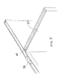
- Figure 5 illustrates two additional aspects of the invention.
- the upper channel 23 may receive a connector element 38 spanning the adjacent ends of two upper frame members 15. Screws or other fixing elements passing through openings in the connector 38 secure the two adjacent panels together.
- a further panel 39 may be fitted to the partition thus formed, by securing to it a batten 40 in the same way as the batten 28 is secured to an original wall.
Landscapes
- Engineering & Computer Science (AREA)
- Architecture (AREA)
- Civil Engineering (AREA)
- Structural Engineering (AREA)
- Physics & Mathematics (AREA)
- Electromagnetism (AREA)
- Panels For Use In Building Construction (AREA)
Applications Claiming Priority (2)
| Application Number | Priority Date | Filing Date | Title |
|---|---|---|---|
| GB9104691A GB2250756B (en) | 1991-03-06 | 1991-03-06 | A modular partition system |
| GB9104691 | 1991-03-06 |
Publications (2)
| Publication Number | Publication Date |
|---|---|
| EP0502736A2 true EP0502736A2 (fr) | 1992-09-09 |
| EP0502736A3 EP0502736A3 (en) | 1993-04-14 |
Family
ID=10691064
Family Applications (1)
| Application Number | Title | Priority Date | Filing Date |
|---|---|---|---|
| EP19920301905 Withdrawn EP0502736A3 (en) | 1991-03-06 | 1992-03-05 | A modular partition system |
Country Status (2)
| Country | Link |
|---|---|
| EP (1) | EP0502736A3 (fr) |
| GB (1) | GB2250756B (fr) |
Cited By (1)
| Publication number | Priority date | Publication date | Assignee | Title |
|---|---|---|---|---|
| US7712260B2 (en) | 2004-07-30 | 2010-05-11 | Groupe Artitalia Inc. | Adjustable wall system |
Families Citing this family (2)
| Publication number | Priority date | Publication date | Assignee | Title |
|---|---|---|---|---|
| GB9408957D0 (en) * | 1994-05-05 | 1994-06-22 | Mann Mcgowan Fabrications Limi | Internal screens and partitions |
| CN102102402B (zh) * | 2011-04-01 | 2012-07-04 | 陈丽燕 | 一种组合式板墙 |
Family Cites Families (5)
| Publication number | Priority date | Publication date | Assignee | Title |
|---|---|---|---|---|
| DE1761358B2 (de) * | 1967-05-12 | 1973-08-23 | Adamovske strojirny, N P, Adamov (Tschechoslowakei) | Seitenziehmarke fuer das seitliche ausrichten von papierboegen an druckmaschinen |
| DE2425432C3 (de) * | 1974-05-25 | 1978-09-14 | Peter 8200 Rosenheim Pertl | Nichttragende Gebäudetrennwand |
| DE2639503A1 (de) * | 1976-09-02 | 1978-03-09 | Guenter Noll | Trennwandsystem, bei dem die wandelemente ohne kenntnis des einbauortes in fixmassen serienmaessig vorgefertigt werden koennen |
| DE3603453A1 (de) * | 1986-02-05 | 1987-09-10 | Connec Ag | Stell- oder trennwand |
| GB8628320D0 (en) * | 1986-11-27 | 1986-12-31 | Collis H G | Walling construction of cavity panel boards |
-
1991
- 1991-03-06 GB GB9104691A patent/GB2250756B/en not_active Expired - Fee Related
-
1992
- 1992-03-05 EP EP19920301905 patent/EP0502736A3/en not_active Withdrawn
Cited By (1)
| Publication number | Priority date | Publication date | Assignee | Title |
|---|---|---|---|---|
| US7712260B2 (en) | 2004-07-30 | 2010-05-11 | Groupe Artitalia Inc. | Adjustable wall system |
Also Published As
| Publication number | Publication date |
|---|---|
| EP0502736A3 (en) | 1993-04-14 |
| GB2250756B (en) | 1995-02-15 |
| GB2250756A (en) | 1992-06-17 |
| GB9104691D0 (en) | 1991-04-17 |
Similar Documents
| Publication | Publication Date | Title |
|---|---|---|
| US5934039A (en) | Apparatus and method for dimensionally uniform building construction using interlocking connectors | |
| US3305982A (en) | Interlocking block building construction | |
| US3537217A (en) | Wall structures | |
| US5836123A (en) | Vinyl-siding corner block | |
| US9366030B2 (en) | Wall panel system | |
| US8286401B2 (en) | Demountable paneling system | |
| EP0400804B1 (fr) | Système de mur | |
| US8635824B2 (en) | Insulation panel system | |
| US4573301A (en) | Interlocking building blocks | |
| US6761004B2 (en) | Reconfigurable room partitioning system | |
| US3245183A (en) | Modular house having dividing component walls dimensioned in correlation with the modular dimension | |
| US4773200A (en) | Wooden suspended ceiling system | |
| US2336435A (en) | Prefabricated house | |
| CA2299925A1 (fr) | Panneaux de construction modulaires et methode de construction de murs a l'aide de ces panneaux | |
| US2054189A (en) | Building construction | |
| US6330775B1 (en) | Prefabricated building wall structure | |
| EP0502736A2 (fr) | Système modulaire de cloison | |
| GB1601071A (en) | Partition wall capable of being dismantled | |
| US3626649A (en) | Prefabricated house | |
| US20090056249A1 (en) | Modular space dividing system | |
| US20040231271A1 (en) | Drop ceiling made of wood | |
| US1960575A (en) | Factory fabricated partition and ceiling construction | |
| WO2007147920A1 (fr) | Système de cloison modulaire | |
| US1485449A (en) | Partition | |
| US20070028558A1 (en) | Structural wood elements and system that can be constructed therefrom |
Legal Events
| Date | Code | Title | Description |
|---|---|---|---|
| PUAI | Public reference made under article 153(3) epc to a published international application that has entered the european phase |
Free format text: ORIGINAL CODE: 0009012 |
|
| AK | Designated contracting states |
Kind code of ref document: A2 Designated state(s): BE ES FR GB NL |
|
| PUAL | Search report despatched |
Free format text: ORIGINAL CODE: 0009013 |
|
| AK | Designated contracting states |
Kind code of ref document: A3 Designated state(s): BE ES FR GB NL |
|
| 17P | Request for examination filed |
Effective date: 19931108 |
|
| RAP1 | Party data changed (applicant data changed or rights of an application transferred) |
Owner name: MODEQUEST PROJECTS LIMITED |
|
| 17Q | First examination report despatched |
Effective date: 19950303 |
|
| 18D | Application deemed to be withdrawn |
Effective date: 19960723 |