EP0503232B1 - Ablaufarmatur, vorzugsweise für Duschwannen - Google Patents
Ablaufarmatur, vorzugsweise für Duschwannen Download PDFInfo
- Publication number
- EP0503232B1 EP0503232B1 EP92100647A EP92100647A EP0503232B1 EP 0503232 B1 EP0503232 B1 EP 0503232B1 EP 92100647 A EP92100647 A EP 92100647A EP 92100647 A EP92100647 A EP 92100647A EP 0503232 B1 EP0503232 B1 EP 0503232B1
- Authority
- EP
- European Patent Office
- Prior art keywords
- drain
- flange ring
- upper housing
- fitment according
- housing
- Prior art date
- Legal status (The legal status is an assumption and is not a legal conclusion. Google has not performed a legal analysis and makes no representation as to the accuracy of the status listed.)
- Expired - Lifetime
Links
- 238000007789 sealing Methods 0.000 claims description 6
- 229920003023 plastic Polymers 0.000 claims description 3
- 239000004033 plastic Substances 0.000 claims description 3
- 239000002184 metal Substances 0.000 claims description 2
- 125000006850 spacer group Chemical group 0.000 claims description 2
- 239000000463 material Substances 0.000 claims 1
- 239000000203 mixture Substances 0.000 claims 1
- 238000007654 immersion Methods 0.000 abstract description 7
- 230000037431 insertion Effects 0.000 abstract 1
- 238000003780 insertion Methods 0.000 abstract 1
- 239000007788 liquid Substances 0.000 description 1
Images



Classifications
-
- E—FIXED CONSTRUCTIONS
- E03—WATER SUPPLY; SEWERAGE
- E03C—DOMESTIC PLUMBING INSTALLATIONS FOR FRESH WATER OR WASTE WATER; SINKS
- E03C1/00—Domestic plumbing installations for fresh water or waste water; Sinks
- E03C1/12—Plumbing installations for waste water; Basins or fountains connected thereto; Sinks
- E03C1/28—Odour seals
- E03C1/29—Odour seals having housing containing dividing wall, e.g. tubular
Definitions
- the invention relates to a drain fitting, preferably for shower trays, consisting of a housing provided with an inlet opening, an outlet connector and a fastening flange and a dip tube inserted into the housing and delimiting the inlet opening and forming part of the odor trap, the housing forming the odor trap encompassing drain channel, which is bounded at the top by an upper housing part, and from a flange ring which is supported in the assembled state at the edge of the drain opening of the shower tray and which is provided with push-through channels for fastening screws which can be screwed into threaded holes in the upper housing part, and the flange ring forms a continuation of the inlet opening .
- a drain fitting of this type is known (EP 0 365 789 A1), in which the inlet opening of the housing and the immersion tube have a circular cross section.
- the invention has for its object to make the drain fitting of the type mentioned so space-saving that the fixing screws for the flange ring which is supported on the edge of the drain opening of the shower tray can be fixed laterally next to the dip tube in the housing.
- a hood covering the inlet opening up to lateral inlet slots is pivotally articulated on the flange ring.
- hood there are no further means for holding and fixing the hood, which so far consist of a bolt arranged centrally on the inside of the hood and of a housing part which extends from the housing base into the immersion tube and is fastened with a recess for receiving the hood Bolzens was provided.
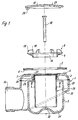
- the drain fitting according to FIG. 1 has a housing 1 which consists of an upper housing part 2 and a lower housing part 3. These parts are welded together.
- the upper housing part has a receptacle 4 for a sealing ring 5, which is provided with a circumferential groove 6, into which an annular web 7 of the upper housing part engages, so that this form fit between the sealing ring and the upper housing part is locked against the upper housing part.
- a flange ring 8 is also provided, which lies with an inclined surface 9 on the upper edge surface of the drain opening, while the sealing ring 5 is pressed against the lower edge surface of the drain opening of the shower tray, specifically when tightening the fastening screws 10, which are inserted through the push-through channels 11 of the flange ring 8 with their threaded shank and screwed into threaded bores 12 of the upper housing part 2.
- the threaded bores 12 are formed by a threaded sleeve 13 made of metal and embedded in the upper housing part 2 made of plastic. Below the threaded sleeve, a channel 14 aligned with the threaded bore is provided in the upper housing part, the diameter of which corresponds to the core diameter of the fastening screw 10, so that when the fastening screw is screwed into this channel, the fastening screw must form the thread itself. This results in a liquid and gas-tight connection between the fastening screw and the upper part of the housing made of plastic.
- a hood 15 is pivotally articulated on the flange ring 8, through which the inlet opening 16, as can be seen from FIG. 3, can be covered except for lateral inlet slots 17.
- the flange ring is equipped with a bearing block 18, which is preferably in one piece with the flange ring.
- This bearing block 18 has stub axles 19 which extend on both sides and onto which two bearing eyes 20 of the hood 15 arranged next to one another and provided with a bore can be sprung open.
- the flange ring 8 is further equipped with spacers 21 which serve to support the pivoted hood 15 and which determine the lateral inlet slots 17.
- the hood 15 is provided with a bore 25 on the side facing away from the axis of rotation 24. Due to this hole, you can quickly find out on which side the hood has to be lifted to initiate the swiveling movement.
- the drain fitting has an immersion pipe 26 which forms part of the odor trap.
- This dip tube is oval in cross section (FIG. 10) and has a flange 27 at the upper end, which is equipped with a sealing ring 28. This flange is supported on an inwardly projecting ring 29 of the upper housing part.
- the housing base is designed to be streamlined and has a region 30 which forms a raised base region which lies centrally below the lower opening of the immersion tube 26 and from which a curvature forming a circumferential groove 31 extends into the side walls of the housing.
- the drain channel 32 of the housing is delimited at the bottom by an inclined surface 33 and at the top by the housing upper part 2. This drain channel 32 opens into a drain port 34.
Landscapes
- Engineering & Computer Science (AREA)
- Environmental & Geological Engineering (AREA)
- Health & Medical Sciences (AREA)
- Life Sciences & Earth Sciences (AREA)
- Hydrology & Water Resources (AREA)
- Public Health (AREA)
- Water Supply & Treatment (AREA)
- Domestic Plumbing Installations (AREA)
- Sink And Installation For Waste Water (AREA)
- External Artificial Organs (AREA)
- Float Valves (AREA)
- Casings For Electric Apparatus (AREA)
- Residential Or Office Buildings (AREA)
- Washing And Drying Of Tableware (AREA)
- Packages (AREA)
- Stackable Containers (AREA)
Description
- Die Erfindung bezieht sich auf eine Ablaufarmatur, vorzugsweise für Duschwannen, bestehend aus einem mit einer Zulauföffnung, einem Ablaufstutzen und einem Befestigungsflansch versehenen Gehäuse und einem in das Gehäuse eingesetzten, die Zulauföffnung begrenzenden, einen Teil des Geruchverschlusses bildenden Tauchrohr, wobei das Gehäuse einen den Geruchverschluß umgreifenden Ablaufkanal aufweist, der nach oben durch ein Gehäuseoberteil begrenzt ist, und aus einem im montierten Zustand sich am Rand der Ablauföffnung der Duschwanne abstützenden Flanschring, der mit Durchsteckkanälen für in Gewindebohrungen des Gehäuseoberteils eindrehbare Befestigungsschrauben versehen ist und wobei der Flanschring eine Fortsetzung der Zulauföffnung bildet.
- Es ist eine Ablaufarmatur dieser Art bekannt (EP 0 365 789 A1), bei der die Zulauföffnung des Gehäuses und das Tauchrohr einen kreisförmigen Querschnitt aufweisen.
- Der Erfindung liegt die Aufgabe zugrunde, die Ablaufarmatur der eingangs genannten Art so platzsparend zu gestalten, daß seitlich neben dem Tauchrohr im Gehäuseoberteil die Befestigungsschrauben für den am Rand der Ablauföffnung der Duschwanne sich abstützenden Flanschring festgelegt werden können.
- Diese Aufgabe wird erfindungsgemäß durch die Merkmale des Patentanspruches 1 gelöst.
- Bei einer vorteilhaften Ausführungsform der erfindungsgemäßen Ablaufarmatur ist an dem Flanschring eine die Zulauföffnung bis auf seitliche Zulaufschlitze abdeckende Haube schwenkbar angelenkt.
- Bei dieser Ausführung entfallen weitere Mittel zur Halterung und Festlegung der Haube, die bisher aus einem an der Innenseite der Haube mittig angeordneten Bolzen und aus einem Gehäuseteil bestehen, das vom Gehäuseboden sich in das Tauchrohr erstreckte und mit einer Ausnehmung zur Aufnahme des an der Haube befestigten Bolzens versehen war.
- Bei der Halterung der Haube ist nicht nur der konstruktive Aufwand geringer als bei der bekannten Ausführung (EP 0 365 789 A1) sondern es wird auch erreicht, daß der gesamte lichte Querschnitt des Tauchrohres als Strömungsquerschnitt zur Verfügung steht.
- Weitere Merkmale der Erfindung ergeben sich aus den Unteransprüchen. Ein Ausführungsbeispiel der erfindungsgemäßen Ablaufarmatur ist in den Zeichnungen dargestellt und wird im folgenden beschrieben. Es zeigen:
- Fig. 1
- das Gehäuse und die weiteren Funktionsteile der Ablaufarmatur in teilweise demontiertem Zustand im Vertikalschnitt,
- Fig. 2
- den Flanschring mit angelenkter Haube im Vertikalschnitt und zwar in der maximalen Öffnungsstellung der Haube,
- Fig. 3
- den Flanschring mit schwenkbar angelenkter Haube entsprechend der Figur 2 im Vertikalschnitt jedoch mit der Haube in der Verschlußstellung,
- Fig. 4
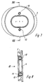
- den Flanschring im Grundriß,
- Fig. 5
- einen Schnitt nach der Linie V-V in Figur 4,
- Fig. 6
- eine Ansicht des Flanschringes in Richtung des Pfeiles VI in Figur 5,
- Fig. 7
- das Gehäuseoberteil im Grundriß,
- Fig. 8
- einen Schnitt nach der Linie VIII-VIII in Figur 7,
- Fig. 9
- eine Ansicht in Richtung des Pfeiles IX in Figur 8 und
- Fig. 10
- einen Schnitt nach der Linie X-X in Figur 1
- Die Ablaufarmatur nach der Figur 1 weist ein Gehäuse 1 auf, das aus einem Gehäuseoberteil 2 und einem Gehäuseunterteil 3 besteht. Diese Teile sind miteinander verschweißt.
- Das Gehäuseoberteil weist eine Aufnahme 4 für einen Dichtungsring 5 auf, der mit einer umlaufenden Nut 6 versehen ist, in die ein Ringsteg 7 des Gehäuseoberteils eingreift, so daß durch diesen Formschluß zwischen dem Dichtungsring und dem Gehäuseoberteil eine Arretierung des Dichtungsringes gegenüber dem Gehäuseoberteil erfolgt.
- Zur Festlegung des Gehäuses 1 an den Randflächen der Ablauföffnung der Duschwanne ist ferner ein Flanschring 8 vorgesehen, der sich mit einer Schrägfläche 9 an die obere Randfläche der Ablauföffnung anlegt, während der Dichtungsring 5 gegen die untere Randfläche der Ablauföffnung der Duschwanne gepreßt wird, und zwar beim Anziehen der Befestigungsschrauben 10, die durch Durchsteckkanäle 11 des Flanschringes 8 mit ihrem Gewindeschaft gesteckt und in Gewindebohrungen 12 des Gehäuseoberteils 2 eingeschraubt werden.
- Die Gewindebohrungen 12 werden durch eine aus Metall gefertigte, in das aus Kunststoff hergestellte Gehäuseoberteil 2 eingebettete Gewindehülse 13 gebildet. Unterhalb der Gewindehülse ist jeweils ein mit der Gewindebohrung fluchtender Kanal 14 im Gehäuseoberteil vorgesehen, dessen Durchmesser dem Kerndurchmesser der Befestigungsschraube 10 entspricht, so daß beim Eindrehen der Befestigungsschraube in diesen Kanal die Befestigungsschraube das Gewinde selbst formen muß. Hierdurch ergibt sich eine flüssigkeits- und gasdichte Verbindung zwischen der Befestigungsschraube und dem aus Kunststoff gefertigten Gehäuseoberteil.
- An dem Flanschring 8 ist eine Haube 15 schwenkbar angelenkt, durch die die Zulauföffnung 16, wie sich aus der Figur 3 ergibt bis auf seitliche Zulaufschlitze 17 abgedeckt werden kann.
- Zur Bildung eines Drehlagers zwischen dem Flanschring 8 und der Haube 15 ist der Flanschring mit einem Lagerbock 18 ausgerüstet, der vorzugsweise mit dem Flanschring einstückig ist. Dieser Lagerbock 18 weist zu beiden Seiten sich erstreckende Achsstummel 19 auf, auf die zwei nebeneinander angeordnete, mit einer Bohrung versehene Lageraugen 20 der Haube 15 aufgefedert werden können.
- Es ist auch denkbar, den Lagerbock an jeder Seite mit einer Ausnehmung auszurüsten, in die Seitennocken der Lageraugen eingefedert werden können.
- Der Flanschring 8 ist ferner mit Abstandshaltern 21 ausgerüstet, die zur Auflage der abgeschwenkten Haube 15 dienen und die die seitlichen Zulaufschlitze 17 bestimmen.
- An der der Drehachse 24 abgewandten Seite ist die Haube 15 mit einer Bohrung 25 versehen. Aufgrund dieser Bohrung kann man sich schnell darüber informieren, an welcher Seite die Haube zur Einleitung der Schwenkbewegung anzuheben ist.
- Die Ablaufarmatur weist ein Tauchrohr 26 auf, das einen Teil des Geruchverschlusses bildet. Dieses Tauchrohr ist im Querschnitt (Figur 10) oval ausgebildet und weist am oberen Ende einen Flansch 27 auf, der mit einem Dichtring 28 ausgestattet ist. Dieser Flansch stützt sich an einem nach innen ragenden Ring 29 des Gehäuseoberteils ab.
- Der Gehäuseboden ist strömungsgünstig ausgebildet und weist einen Bereich 30 auf, der einer hochgezogenen Bodenbereich bildet, der mittig unterhalb der unteren Öffnung des Tauchrohres 26 liegt und von der sich eine eine umlaufende Rinne 31 bildende in die Seitenwände des Gehäuses übergehende Wölbung erstreckt.
- Der Ablaufkanal 32 des Gehäuses wird unten durch eine Schrägfläche 33 und oben durch das Gehäuseoberteil 2 begrenzt. Dieser Ablaufkanal 32 mündet in einen Ablaufstutzen 34 ein.
Claims (9)
- Ablaufarmatur, vorzugsweise für Duschwannen, bestehend aus einem mit einer Zulauföffnung, einem Ablaufstutzen und einem Befestigungsflansch versehenen Gehäuse (1) und einem in das Gehäuse (1) eingesetzten, die Zulauföffnung begrenzenden, einen Teil des Geruchverschlusses bildenden Tauchrohr (26), wobei das Gehäuse (1) einen den Geruchverschluß umgreifenden Ablaufkanal (32) aufweist, der nach oben durch ein Gehäuseoberteil (2) begrenzt ist und aus einem im montierten Zustand sich am Rand der Ablauföffnung der Duschwanne abstützenden Flanschring (8) besteht, der mit Durchsteckkanälen für in Gewindebohrungen des Gehäuseoberteils eindrehbare Befestigungsschrauben versehen ist und wobei der Flanschring (8) eine Frotsetzung der Zulauföffnung (16) bildet, dadurch gekennzeichnet, daß der im Flanschring (8) liegende Teil der Zulauföffnung (16) und das Tauchrohr (26) im Querschnitt oval ausgebildet sind und benachbart den parallel zur großen Achse der Zulauföffnung (16) verlaufenden Längsseiten die Durchsteckkanäle (11) für Befestigungsschrauben angeordnet sind.
- Ablaufarmatur nach Anspruch 1, dadurch gekennzeichnet, daß die Gewindebohrungen (12) im Gehäuseoberteil (2) eine aus Metall gefertigte, in das aus Kunststoff hergestellte Gehäuseoberteil (2) eingebettete Gewindehülse (13) aufweisen und unterhalb der Gewindebohrung der Gewindehülse (13) und fluchtend damit ein Kanal (14) im Gehäuseoberteil vorgesehen ist, dessen Durchmesser in etwa dem Kerndurchmesser der Befestigungsschraube (10) entspricht.
- Ablaufarmatur nach Anspruch 1 oder 2, dadurch gekennzeichnet, daß der Gehäuseboden in der Mitte einen hochgezogenen Bodenbereich (30) aufweist, von der sich eine eine umlaufende Rinne (31) bildende, in die Seitenwände des Gehäuses übergehende Wölbung erstreckt.
- Ablaufarmatur nach Anspruch 1, dadurch gekennzeichnet, daß an dem Flanschring (8) eine die Ablauföffnung (16) bis auf seitliche Zulaufschlitze (17) abdeckende Haube (15) schwenkbar angelenkt ist.
- Ablaufarmatur nach Anspruch 4, dadurch gekennzeichnet, daß der Flanschring (8) einen mit seitlich sich erstreckenden Achsstummeln (19) ausgerüsteten Lagerbock (18) aufweist und auf die Achsstummel zwei nebeneinander angeordnete Lagerungen (20) der Haube (15) auffederbar sind.
- Ablaufarmatur nach Anspruch 5, dadurch gekennzeichnet, daß der Lagerbock (18) an jeder Seite eine Ausnehmung aufweist, in die Seitennocken der Lageraugen einfederbar sind.
- Ablaufarmatur nach einem der vorhergehenden Ansprüche, dadurch gekennzeichnet, daß der Flanschring (8) Abstandshalter (21) zur Auflage der abgeschwenkten Haube (15) und zur Begrenzung der seitlichen Zulaufschlitze (17) aufweist.
- Ablaufarmatur nach Anspruch 4, dadurch gekennzeichnet, daß in der Haube (15) an der der Drehachse (24) abgewandten Seite eine Bohrung (25) vorgesehen ist.
- Ablaufarmatur nach einem der vorhergehenden Ansprüche, dadurch gekennzeichnet, daß das Gehäuseoberteil (2) mit einer Aufnahme (4) für einen Dichtungsring (5) und mit einem Ringsteg (7) versehen ist, der in eine Ringnut (6) des Dichtungsrings eingreift.
Applications Claiming Priority (2)
| Application Number | Priority Date | Filing Date | Title |
|---|---|---|---|
| DE9102860U | 1991-03-09 | ||
| DE9102860U DE9102860U1 (de) | 1991-03-09 | 1991-03-09 | Ablaufarmatur, vorzugsweise für Duschwannen |
Publications (2)
| Publication Number | Publication Date |
|---|---|
| EP0503232A1 EP0503232A1 (de) | 1992-09-16 |
| EP0503232B1 true EP0503232B1 (de) | 1996-08-28 |
Family
ID=6865098
Family Applications (1)
| Application Number | Title | Priority Date | Filing Date |
|---|---|---|---|
| EP92100647A Expired - Lifetime EP0503232B1 (de) | 1991-03-09 | 1992-01-16 | Ablaufarmatur, vorzugsweise für Duschwannen |
Country Status (6)
| Country | Link |
|---|---|
| EP (1) | EP0503232B1 (de) |
| AT (1) | ATE141984T1 (de) |
| DE (2) | DE9102860U1 (de) |
| DK (1) | DK0503232T3 (de) |
| ES (1) | ES2091339T3 (de) |
| GR (1) | GR3021469T3 (de) |
Families Citing this family (9)
| Publication number | Priority date | Publication date | Assignee | Title |
|---|---|---|---|---|
| GB9504398D0 (en) * | 1995-03-06 | 1995-04-26 | Upton John | An improved water trap |
| DE29610312U1 (de) * | 1996-06-12 | 1996-08-22 | Fa. Franz Viegener Ii, 57439 Attendorn | Ablaufarmatur, vorzugsweise für eine Duschwanne |
| FR2771431B1 (fr) * | 1997-11-24 | 1999-12-31 | Sanitaire Accessoires Services | Ensemble de vidage pour appareils sanitaires |
| DE20101787U1 (de) * | 2001-02-02 | 2002-06-13 | Franz Viegener II GmbH & Co. KG, 57439 Attendorn | Ablauf |
| DE10360310A1 (de) * | 2003-12-18 | 2005-07-21 | Dallmer Gmbh & Co. Kg | Ablaufvorrichtung |
| DE202008011197U1 (de) * | 2008-08-22 | 2009-12-31 | Viega Gmbh & Co. Kg | Ablaufarmatur mit Geruchverschluss |
| DE202008011272U1 (de) * | 2008-08-25 | 2010-02-11 | Viega Gmbh & Co. Kg | Ablauf, insbesondere für bodengleiche Duschen |
| CH703597B1 (de) * | 2010-09-01 | 2012-04-30 | Urs Gassmann | Mehrzweck-Siphon. |
| EP3272954B1 (de) * | 2016-07-22 | 2020-08-19 | Geberit International AG | Ablaufanordnung |
Family Cites Families (6)
| Publication number | Priority date | Publication date | Assignee | Title |
|---|---|---|---|---|
| US1566052A (en) * | 1924-02-27 | 1925-12-15 | Dabrowski Lothar Von | Trap and drain |
| US2136945A (en) * | 1937-03-30 | 1938-11-15 | Klein Felix | Odor-trap draining device |
| US3445867A (en) * | 1966-07-21 | 1969-05-27 | Walther Loffler | Container for liquids and means for discharging liquids therefrom |
| FR2402140A1 (fr) * | 1977-08-31 | 1979-03-30 | Ericson Sture | Dispositif de valve automatique pour canalisations sanitaires d'evacuation d'eaux usees et installation sanitaire comprenant de telles valves automatiques |
| DE3141878C1 (de) * | 1981-10-22 | 1983-04-14 | Hans Grohe Gmbh & Co Kg, 7622 Schiltach | "Dichtungsring für Badewannenablaufventile" |
| DE8813543U1 (de) * | 1988-10-28 | 1988-12-15 | Fa. Franz Viegener Ii, 5952 Attendorn | Ablaufarmatur, vorzugsweise für Duschwannen |
-
1991
- 1991-03-09 DE DE9102860U patent/DE9102860U1/de not_active Expired - Lifetime
-
1992
- 1992-01-16 EP EP92100647A patent/EP0503232B1/de not_active Expired - Lifetime
- 1992-01-16 ES ES92100647T patent/ES2091339T3/es not_active Expired - Lifetime
- 1992-01-16 DE DE59206971T patent/DE59206971D1/de not_active Expired - Fee Related
- 1992-01-16 DK DK92100647.4T patent/DK0503232T3/da active
- 1992-01-16 AT AT92100647T patent/ATE141984T1/de active
-
1996
- 1996-10-24 GR GR960402824T patent/GR3021469T3/el unknown
Also Published As
| Publication number | Publication date |
|---|---|
| DK0503232T3 (da) | 1996-09-16 |
| ATE141984T1 (de) | 1996-09-15 |
| ES2091339T3 (es) | 1996-11-01 |
| GR3021469T3 (en) | 1997-01-31 |
| DE9102860U1 (de) | 1991-05-29 |
| DE59206971D1 (de) | 1996-10-02 |
| EP0503232A1 (de) | 1992-09-16 |
Similar Documents
| Publication | Publication Date | Title |
|---|---|---|
| DE3713503C1 (de) | Verschlussdeckel aus Kunststoff | |
| DE3538744A1 (de) | Reinigungsvorrichtung fuer die durchgangskanaele eines endoskopes | |
| EP0503232B1 (de) | Ablaufarmatur, vorzugsweise für Duschwannen | |
| DE10125037B4 (de) | Tankverschluß | |
| DE8910933U1 (de) | Klapptritt für Wohnmobile und dgl. Fahrzeuge | |
| DE29610290U1 (de) | Flüssigkeitsfilter | |
| DE4237674A1 (de) | Rohrschelle | |
| DE102010000423A1 (de) | Verfahren zum Verstellen der Länge eines teleskopischen Wasserrohrs und dessen Struktur | |
| DE102010015885B4 (de) | Elektrisches Verteilergehäuse | |
| EP1002907A1 (de) | Sanitärarmatur | |
| DE3918321C2 (de) | Ablauf mit einem Wassergeruchsverschlußeinsatz | |
| EP0536471B1 (de) | Montageplatte für Möbelscharniere | |
| EP1389546B1 (de) | Gleitbackenführung für öffnungsfähige Fahrzeugdächer oder Fahrzeugklappen | |
| DE20100826U1 (de) | Ablauf mit Geruchsverschluss | |
| DE9209268U1 (de) | Leuchte für Fahrzeuge | |
| EP2703573B1 (de) | Ablaufgarnitur und Badewanne bzw. Duschtasse mit einer derartigen Ablaufgarnitur | |
| CH716848B1 (de) | Becken mit Bodenablauf. | |
| DE10210349A1 (de) | Reinigungsvorrichtung für einen Scherkopf eines Trockenrasierapparates | |
| DE4425493C2 (de) | Scheinwerfer-Reinigungsvorrichtung | |
| EP1013837B1 (de) | Ablaufgarnitur für eine Badewanne | |
| EP3783158B1 (de) | Ab- und überlaufarmatur für eine badewanne | |
| DE2819065C2 (de) | Einhebel-Mischarmatur | |
| DE10022448A1 (de) | Außenrückblickspiegel für Fahrzeuge, vorzugseise für Kraftfahrzeuge | |
| EP0255873A2 (de) | Vorrichtung zum Einstellen und Fixieren der Höhenlage eines Deckels eines Fahrzeugdaches | |
| DE29519146U1 (de) | Füllvorrichtung für Batteriezellen |
Legal Events
| Date | Code | Title | Description |
|---|---|---|---|
| PUAI | Public reference made under article 153(3) epc to a published international application that has entered the european phase |
Free format text: ORIGINAL CODE: 0009012 |
|
| AK | Designated contracting states |
Kind code of ref document: A1 Designated state(s): AT CH DE DK ES FR GB GR IT LI NL SE |
|
| 17P | Request for examination filed |
Effective date: 19920729 |
|
| 17Q | First examination report despatched |
Effective date: 19950112 |
|
| GRAG | Despatch of communication of intention to grant |
Free format text: ORIGINAL CODE: EPIDOS AGRA |
|
| GRAH | Despatch of communication of intention to grant a patent |
Free format text: ORIGINAL CODE: EPIDOS IGRA |
|
| ITF | It: translation for a ep patent filed | ||
| GRAH | Despatch of communication of intention to grant a patent |
Free format text: ORIGINAL CODE: EPIDOS IGRA |
|
| GRAA | (expected) grant |
Free format text: ORIGINAL CODE: 0009210 |
|
| AK | Designated contracting states |
Kind code of ref document: B1 Designated state(s): AT CH DE DK ES FR GB GR IT LI NL SE |
|
| REF | Corresponds to: |
Ref document number: 141984 Country of ref document: AT Date of ref document: 19960915 Kind code of ref document: T |
|
| REG | Reference to a national code |
Ref country code: CH Ref legal event code: NV Representative=s name: KATZAROV S.A. |
|
| REG | Reference to a national code |
Ref country code: DK Ref legal event code: T3 |
|
| REF | Corresponds to: |
Ref document number: 59206971 Country of ref document: DE Date of ref document: 19961002 |
|
| GBT | Gb: translation of ep patent filed (gb section 77(6)(a)/1977) |
Effective date: 19961001 |
|
| REG | Reference to a national code |
Ref country code: ES Ref legal event code: FG2A Ref document number: 2091339 Country of ref document: ES Kind code of ref document: T3 |
|
| PGFP | Annual fee paid to national office [announced via postgrant information from national office to epo] |
Ref country code: SE Payment date: 19961212 Year of fee payment: 6 |
|
| PGFP | Annual fee paid to national office [announced via postgrant information from national office to epo] |
Ref country code: FR Payment date: 19961216 Year of fee payment: 6 |
|
| PGFP | Annual fee paid to national office [announced via postgrant information from national office to epo] |
Ref country code: GR Payment date: 19961219 Year of fee payment: 6 |
|
| ET | Fr: translation filed | ||
| REG | Reference to a national code |
Ref country code: GR Ref legal event code: FG4A Free format text: 3021469 |
|
| PGFP | Annual fee paid to national office [announced via postgrant information from national office to epo] |
Ref country code: ES Payment date: 19970114 Year of fee payment: 6 |
|
| PGFP | Annual fee paid to national office [announced via postgrant information from national office to epo] |
Ref country code: GB Payment date: 19970115 Year of fee payment: 6 |
|
| PGFP | Annual fee paid to national office [announced via postgrant information from national office to epo] |
Ref country code: DE Payment date: 19970117 Year of fee payment: 6 |
|
| PGFP | Annual fee paid to national office [announced via postgrant information from national office to epo] |
Ref country code: DK Payment date: 19970128 Year of fee payment: 6 |
|
| PGFP | Annual fee paid to national office [announced via postgrant information from national office to epo] |
Ref country code: AT Payment date: 19970130 Year of fee payment: 6 |
|
| PGFP | Annual fee paid to national office [announced via postgrant information from national office to epo] |
Ref country code: NL Payment date: 19970131 Year of fee payment: 6 |
|
| PGFP | Annual fee paid to national office [announced via postgrant information from national office to epo] |
Ref country code: CH Payment date: 19970304 Year of fee payment: 6 |
|
| PLBE | No opposition filed within time limit |
Free format text: ORIGINAL CODE: 0009261 |
|
| STAA | Information on the status of an ep patent application or granted ep patent |
Free format text: STATUS: NO OPPOSITION FILED WITHIN TIME LIMIT |
|
| 26N | No opposition filed | ||
| PG25 | Lapsed in a contracting state [announced via postgrant information from national office to epo] |
Ref country code: GB Free format text: LAPSE BECAUSE OF NON-PAYMENT OF DUE FEES Effective date: 19980116 Ref country code: AT Free format text: LAPSE BECAUSE OF NON-PAYMENT OF DUE FEES Effective date: 19980116 |
|
| PG25 | Lapsed in a contracting state [announced via postgrant information from national office to epo] |
Ref country code: SE Free format text: LAPSE BECAUSE OF NON-PAYMENT OF DUE FEES Effective date: 19980117 Ref country code: ES Free format text: LAPSE BECAUSE OF EXPIRATION OF PROTECTION Effective date: 19980117 |
|
| PG25 | Lapsed in a contracting state [announced via postgrant information from national office to epo] |
Ref country code: LI Free format text: LAPSE BECAUSE OF NON-PAYMENT OF DUE FEES Effective date: 19980131 Ref country code: GR Free format text: LAPSE BECAUSE OF NON-PAYMENT OF DUE FEES Effective date: 19980131 Ref country code: FR Free format text: THE PATENT HAS BEEN ANNULLED BY A DECISION OF A NATIONAL AUTHORITY Effective date: 19980131 Ref country code: CH Free format text: LAPSE BECAUSE OF NON-PAYMENT OF DUE FEES Effective date: 19980131 |
|
| PG25 | Lapsed in a contracting state [announced via postgrant information from national office to epo] |
Ref country code: DK Free format text: LAPSE BECAUSE OF NON-PAYMENT OF DUE FEES Effective date: 19980202 |
|
| PG25 | Lapsed in a contracting state [announced via postgrant information from national office to epo] |
Ref country code: NL Free format text: LAPSE BECAUSE OF NON-PAYMENT OF DUE FEES Effective date: 19980801 |
|
| GBPC | Gb: european patent ceased through non-payment of renewal fee |
Effective date: 19980116 |
|
| REG | Reference to a national code |
Ref country code: CH Ref legal event code: PL |
|
| NLV4 | Nl: lapsed or anulled due to non-payment of the annual fee |
Effective date: 19980801 |
|
| PG25 | Lapsed in a contracting state [announced via postgrant information from national office to epo] |
Ref country code: DE Free format text: LAPSE BECAUSE OF NON-PAYMENT OF DUE FEES Effective date: 19981001 |
|
| EUG | Se: european patent has lapsed |
Ref document number: 92100647.4 |
|
| REG | Reference to a national code |
Ref country code: FR Ref legal event code: ST |
|
| REG | Reference to a national code |
Ref country code: ES Ref legal event code: FD2A Effective date: 20000201 |
|
| REG | Reference to a national code |
Ref country code: DK Ref legal event code: EBP |
|
| PG25 | Lapsed in a contracting state [announced via postgrant information from national office to epo] |
Ref country code: IT Free format text: LAPSE BECAUSE OF NON-PAYMENT OF DUE FEES;WARNING: LAPSES OF ITALIAN PATENTS WITH EFFECTIVE DATE BEFORE 2007 MAY HAVE OCCURRED AT ANY TIME BEFORE 2007. THE CORRECT EFFECTIVE DATE MAY BE DIFFERENT FROM THE ONE RECORDED. Effective date: 20050116 |