EP0503474B1 - Leitweglenkungssystem für Linearmultiplexer mit Einfügung und Ausblendung von Kanälen - Google Patents
Leitweglenkungssystem für Linearmultiplexer mit Einfügung und Ausblendung von Kanälen Download PDFInfo
- Publication number
- EP0503474B1 EP0503474B1 EP92103752A EP92103752A EP0503474B1 EP 0503474 B1 EP0503474 B1 EP 0503474B1 EP 92103752 A EP92103752 A EP 92103752A EP 92103752 A EP92103752 A EP 92103752A EP 0503474 B1 EP0503474 B1 EP 0503474B1
- Authority
- EP
- European Patent Office
- Prior art keywords
- signal
- switch
- switches
- drop
- routing system
- Prior art date
- Legal status (The legal status is an assumption and is not a legal conclusion. Google has not performed a legal analysis and makes no representation as to the accuracy of the status listed.)
- Expired - Lifetime
Links
Images



Classifications
-
- H—ELECTRICITY
- H04—ELECTRIC COMMUNICATION TECHNIQUE
- H04J—MULTIPLEX COMMUNICATION
- H04J3/00—Time-division multiplex systems
- H04J3/02—Details
- H04J3/08—Intermediate station arrangements, e.g. for branching, for tapping-off
Definitions
- the present invention relates to a routing system for a linear add-drop multiplexer, and more particularly to a routing system for a linear add-drop multiplexer having a cross-connect function, according to the preamble of claims 1 and 15.
- a routing system of this kind is known from US-A-4 967 405.
- ADM add-drop multiplexers
- linear ADMs receive signals from terminals connected to the opposite ends of a bidirectional linear transmission line, and transmit signals to the terminals.
- East and West terminals one of the terminals (hereinafter referred to as East and West terminals) is selected for a path in use and the other for a path not in use.
- a channel connected to the terminal selected for a channel in use is dropped.
- the ADM has a routing unit for establishing the path in use to drop the channel to lower signal levels.
- the ADM For signal transmission, one of the East and West terminals is selected for a path in use and the other for a path not in use, with an add channel connected to the path in use.
- the ADM has a gate for transmitting a signal to the path in use.
- FIG. 1 of the accompanying drawings is a diagram of an overall arrangement of an optical transmission system in which ADMs are disposed between linear transmission lines.
- ADMs 72, 73, 74 are disposed between linear optical transmission lines 70a through 70h, with line terminal equipment (LTE) 71, 75 connected to opposite ends thereof.
- LTE line terminal equipment
- a multiplexed optical signal is transmitted at a rate of 600 Mbits/s over the optical transmission lines 70a through 70h.
- transmitter/receivers 76, 77, 78, 79 and 80 for lower signal levels which are connected to exchanges 81, 82, 83, 84, 85, 86, 87, 88 and 89.
- Telephone sets 90, 91, 92, 93, 94 and 95 or other terminal devices are connected to the exchanges 81, 82, 83, 84, 85, 86, 87, 88 and 89.
- Input/output devices 96, 97 and 98 are connected to the respective ADMs 72, 73, 74 for applying path connecting commands to the ADMs 72, 73, 74.
- multiplexed optical signals transmitted from the LTE 71, 75 are converted into electric signals and then demultiplexed by the ADMs 72, 73, 74.
- the ADMs 72, 73, 74 then transmit lower-level signals to the transmitter/receivers 76, 77, 78, 79 and 80 through a path that has been established, thereby providing a drop channel.
- the ADMs 72, 73, 74 pick up signals, through a path that has been established, out of the lower-level signals transmitted from the corresponding transmitter/receivers 76, 77, 78, 79 and 80, and also out of demultiplexed signals (through signals) that are not transmitted to the transmitter/receivers 76, 77, 78, 79 and 80, thus establishing an add channel. Then, the ADMs 72, 73 and 74 multiplex the picked-up signals, convert them into optical signals, and output the optical signals to the LTE 71, 75. The LTE 71, 75 also establish a drop channel or an add channel based on the established path.
- the transmitter/receivers 76, 77, 78, 79 and 80 convert the signals that have been transmitted at a rate of 45 Mbits/s from the LTE 71, the ADMs 72, 73, 74 and the LTE 75, into signals at a rate of 1.5 Mbits/s, and transmit the converted signals to the exchanges 81 through 89.
- the transmitter/receivers 76 through 80 convert signals transmitted at 1.5 Mbits/s from the exchanges 81, 82, 83, 84, 85, 86, 87, 88 and 89 into signals at 45 Mbits/s, and transmit the converted signals to the LTE 71, the ADMs 72, 73, 74 and the LTE 75.
- the exchanges 81, 82, 83, 84, 85, 86, 87, 88 and 89 convert the signals that have been transmitted at 1.5 Mbits/s from the transmitter/receivers 76, 77, 78, 79 and 80, into signals at a rate of 64 Kbits/s, and transmit the converted signals to the telephone sets 90, 91, 92, 93, 94 and 95.
- the exchanges 81, 82, 83, 84, 85, 86, 87, 88 and 89 convert signals at 64 Kbits/s from the telephone sets 90, 91, 92, 93, 94 and 95 into signals at 1.5 Mbits/s, and transmit the converted signals to the transmitter/receivers 76, 77, 78, 79 and 80.
- FIG. 2 of the accompanying drawings is a block diagram of a conventional ADM for use in the above optical transmission system.
- a multiplexed optical signal of higher signal level transmitted from an optical transmission line 111 connected to an East terminal is converted into an electric signal by an optoelectronic (O/E) transducer 112.
- the electric signal is then separated by a demultiplexer (DMUX) 113 into a plurality of channels, which are then transmitted to drop switches 114 and add switches 134.
- DMUX demultiplexer
- Each of the drop switches 114 is connected to all of the channels, and each add switch 134 is connected to one of the channels, thus establishing a through channel.
- the drop switches 114 select, as a drop channel, one of the channels separated by the demultiplexer 113 in response to a selection signal from a controller 160, and transmit the signal through the selected channel to channel switches 150 for lower signal levels. There are as many channel switches 150 as the number of channels, and the signals from the drop switches 114 are transmitted to these channel switches 150.
- a drop channel to be selected has previously been indicated to the controller 160 by keystrokes entered through an input/output device 165.
- the selection signal applied to the drop switches 114 represents the drop channel thus selected.
- the channel switches 150 select either the output signal from the drop switches 114 (i.e., the signal received from the East terminal), or an output signal from drop switches 144 (described below -- i.e., a signal received from a West terminal), and transmit the selected signal to a transmitter/receiver 170 for lower signal levels.
- the above selection made by the channel switches 150 is based on a selection signal that is produced by the controller 160 according to keystrokes entered through the input/output device 165, and which is applied to path switches 150a in the respective channel switches 150.
- a multiplexed optical signal of higher signal level transmitted from an optical transmission line 141 connected to a West terminal is converted into an electric signal by an optoelectronic (O/E) transducer 142.
- the electric signal is then separated by a demultiplexer (DMUX) 143 into a plurality of channels, which are then transmitted to drop switches 144 and add switches 124.
- DMUX demultiplexer
- Each of the drop switches 144 is connected to all the channels, and each add switch 124 is connected to one of the channels.
- the drop switches 144 select, as a drop channel, one of the channels separated by the demultiplexer 143 in response to a selection signal from a controller 160, and transmit the signal through the selected channel to the channel switches 150 for lower signal levels. As described above, there are as many channel switches 150 as the number of channels, and the signals from the drop switches 144 are transmitted to these channel switches 150.
- a signal transmitted from the transmitter/receiver 170 is sent through gates (not shown) in the channel switches 150 to the add switches 124 and the add switches 134.
- the channel switches 150 which are as many as the channels, are connected to the add switches 124, 134, so that all signals from the channel switches 150 are sent to any one of the add switches 124, 134.
- the add switches 124 connected to the East terminal select one of the signals in the channels and the one-channel signal from the demultiplexer 143, thus establishing an add channel, and outputs the selected signal to a multiplexer 123.
- the add switches 124 select the signal based on a selection signal transmitted from the controller 160 representing a channel to be selected, as indicated by the input/output device 165.
- the multiplexer 123 is supplied with signals transmitted from the add switches 124 in the respective channels.
- the multiplexer 123 multiplexes the supplied signals into an electric signal, which is then applied to an electro-optic (E/O) transducer 122.
- the electric signal is then converted by the electro-optic transducer 122 into an optical signal that is outputted to an optical transmission line 121.
- the add switches 134 connected to the West terminal select one of the signals in the channels and the one-channel signal from the demultiplexer 113, and output the selected signal to a multiplexer 133.
- the multiplexer 133 multiplexes the signals supplied from the add switches 134 in the respective channels into an electric signal, which is then applied to an electro-optic (E/0) transducer 132.
- the electric signal is then converted by the electro-optic transducer 132 into an optical signal that is outputted to an optical transmission line 131.
- the drop switches connected to the East terminal, the drop switches connected to the West terminal, the add switches connected to the East terminal, the add switches connected to the West terminal, and the channel switches for lower signal levels operate to change channels based on established paths. Therefore, the transmitter/receivers for lower signal levels can be connected to any channels connected to the East and West terminals.
- the above path exchange capability is known as a cross-connect function.
- the input/output device 165 is required to command the controller 160 for establishing paths with respect to the five switch assemblies, i.e., the drop switches 114, 144, the add switches 124, 134, and the channel switches 150 which are provided for each of a plurality of channels. Since the number of switch assemblies to be addressed for establishing paths is equal to 5 multiplied by the number of channels, the process of establishing paths with the input/output device 165 is complex and time-consuming. Therefore, there has been a demand for a simplified process of establishing paths which is to be carried out by the input/output device 165.
- the path switches 150a in the respective channel switches 150 operate to determine which paths connected to the East or West terminal, are to be dropped based on the selection from the controller 160.
- the channel switches 150 are normally composed of respective individual block units. Consequently, the block units of the channel switches 150 are connected to the controller 160 by respective control lines.
- a program for establishing paths with respect to the channel switches 150 approaches the individual path switches 150a in the channel switches.
- the drop switches connected to the East terminal, the drop switches connected to the West terminal, the add switches connected to the East terminal, and the add switches connected to the West terminal are normally assembled as four block units, respectively. These four block units are connected to the controller 160 through respective control lines. Therefore, no individual control lines are connected from the controller 160 to the individual drop or add switches. A program for establishing paths with respect to these switches first approaches the block units, and then controls the individual drop or add switches.
- the program for establishing paths with respect to the channel switches is more complex than the program for establishing paths with respect to the drop and add switches, because the former program is required to approach the individual channel switches rather than a single block unit. As a consequence, the program for establishing paths with respect to the channel switches is relatively large in scale and highly expensive to develop.
- a time division multiplexer including a plurality of multiplexing units and a plurality of terminal adapters is known.
- the multiplexer further includes a repeating adapter which has a memory and which is connected to two or more multiplexing units to be accessed for temporary storage of the data to be repeated from one to the other.
- Another object of the present invention is to provide a routing system for a linear ADM, which operates to establish paths according to a program that is relatively small in scale and inexpensive to develop.
- a routing system for a linear add-drop multiplexer having a first drop switch connected to a first transmission line, a second drop switch connected to a second transmission line and a channel switch for lower levels connected to the first drop switch and the second drop switch.
- the routing system includes a first selection switch, which is provided in the first drop switch, for selecting one of a plurality of channels connected to the first transmission line and outputting a signal transmitted through the selected channel.
- a first selector which is provided in the first drop switch, selectively outputs and inhibits the signal transmitted from the first selection switch.
- a second selection switch which is provided in the second drop switch, selects one of a plurality of channels connected to the second transmission line and outputs a signal transmitted through the selected channel.
- a second selector which is provided in the second drop switch, inhibits the signal transmitted from the second selection switch when the first selector outputs the signal, and outputs the signal when the first selector inhibits the signal.
- Output means which is provided in the channel switch, outputs the signals transmitted from the first and second selectors to a transmitter/receiver for lower signal levels.
- a linear ADM comprises a drop switch 10 connected to an East terminal, an add switch 20 connected to the East terminal, an add switch 30 connected to a West terminal, a drop switch 40 connected to the West terminal, and a channel switch 50 for lower signal levels.
- the drop switch 10 has a selection switch 11 and a selector 12, and the drop switch 40 also has a selection switch 41 and a selector 42.
- the selection switch 11 is responsive to a selection signal from a controller 1 to select one of the signals supplied in a plurality of channels, and output the selected signal to the selector 12.
- the selected signal is referred to as a "first signal.”
- the selection signal is output from the controller 1 based on a command from an input/output device 2 which is operated to established a path.
- the selection switch 11 In addition to the first signal, the selection switch 11 outputs a second signal from an unequipped code (UE) section 11a to the selector 12, where the second signal is equal to a selected signal having all data bits set to 0.
- the selector 12 In response to the selection signal from the controller 1, the selector 12 outputs one of the signals applied thereto to the channel switch 50. Since the second signal is equal to the selected signal having all data bits set to 0, the application of the second signal from the selector 12 to the channel switches 50 is physically equivalent to the application of no selected signal to the channel switch 50. This also holds true for a fourth signal (described below).
- the selection switch 41 of the drop switch 40 operates in exactly the same manner as the selection switch 11. More specifically, the selection switch 41 is responsive to a selection signal from the controller 1 to select one of the signals supplied in a plurality of channels, and to output the selected signal to the selector 42, where the selected signal is referred to as a "third signal.” In addition to the third signal, the selection switch 41 outputs a fourth signal from an unequipped code (UE) section 41a thereof to the selector 42, where the fourth signal is equal to a selected signal having all data bits set to 0.
- UE unequipped code
- the selector 42 selects and outputs the fourth signal to the channel switch 50, and when the selector 12 outputs the second signal, the selector 42 selects and outputs the third signal to the channel switch 50. Therefore, the channel switch 50 is supplied with a significant signal (which is not a signal having data bits which are all 0) from either the drop switch 10 or the drop switch 40, one at a time, without any signal overlapping. The channel switch 50 then outputs the supplied signal, as it is, to a transmitter/receiver 70 for lower signal levels.
- the add switch 20 comprises a selection switch 21 and a selector 23, and the add switch 30 also comprises a selection switch 31 and a selector 33.
- the channel switch 50 has a first code adder 52 which serves as a first code adding means and a second code adder 53 which serves as a second code adding means.
- the first code adder 52 adds an equipped code or an unequipped code to a received signal at a predetermined code position thereof, and the channel switch 50 outputs the signal with a code added thereto to the add switch 21.
- the second code adder 53 adds an unequipped code or an equipped code, complementarily to those added by the first code adder 52, to a received signal at a predetermined code position thereof, and the channel switch 50 outputs the signal with a code added thereto to the add switch 31. Whether an equipped code or an unequipped code is to be added by the first and second code adders 52, 53 is specified by the input/output device 2, which controls the controller 1 to apply a code selection signal to the channel switch 50.
- the selection switch 21 selects one of the signals transmitted in a plurality of channels from channel switches for lower signal levels, and a one-channel through signal from the drop switch 40, and outputs the selected signal to the selector 23.
- the selection switch 21 has an unequipped code (UE) section 21a in which all data bits of the selected signal are set to 0, and outputs the signal to the selector 23.
- the selector 23 normally outputs the former one of the two supplied signals. However, when the path is broken, i.e., when the ADM does not add any channel or does not establish any through channel, the selector 23 outputs the latter signal with the unequipped code added thereto according to the common generic criteria.
- the selection switch 31 and the selector 33 of the add switch 30 operate in exactly the same manner as the selection switch 21 and the selector 23 of the add switch 20.
- the linear ADM includes drop switches 10a through 10n in 12 channels and add switches 20a through 20n in 12 channels.
- the drop switches 10a through 10n and the add switches 20a through 20n are connected to an East terminal.
- the linear ADM also includes add switches 30a through 30n in 12 channels and drop switches 40a through 40n in 12 channels.
- the add switches 30a through 30n and the drop switches 40a through 40n are connected to a West terminal.
- the linear ADM further includes channel switches 50a through 50n for lower signal levels, demultiplexers (DMUX) 3 and 6, multiplexers (MUX) 4 and 5, and a controller 1.
- the controller 1 is in the form of a microprocessor having a ROM which stores a control program.
- the drop switches 10a through 10n, the add switches 20a through 20n, the add switches 30a through 30n, and the drop switches 40a through 40n are assembled as respective four block units, which are connected through respective control lines to the controller 1.
- the channel switches 50a through 50n are assembled as respective 12 block units, which are connected through respective control lines to the controller 1.
- the linear ADM also has electro-optic transducers (E/0) and optoelectronic transducers (O/E) that are omitted from the illustration.
- All signals in 12 channels which have been demultiplexed by the demultiplexer 3 are supplied to each of the drop switches 10a through 10n, and different channels of the respective 12-channel signals are inputted as through channels to the respective add switches 30a through 30n. Single output signals from the respective drop switches 10a through 10n are supplied respectively to the channel switches 50a through 50n.
- all signals in 12 channels which have been demultiplexed by the demultiplexer 6 are supplied to each of the drop switches 40a through 40n, and different channels of the respective 12-channel signals are inputted as through channels to the respective add switches 20a through 20n.
- Single output signals from the respective drop switches 40a through 40n are supplied respectively to the channel switches 50a through 50n.
- the channel switches 50a through 50n output all output signals, i.e., output signals in 12 channels, to each of the add switches 20a through 20n.
- the add switches 20a through 20n output respective single output signals to the multiplexer 4.
- all the output signals, i.e., the output signals in 12 channels, from the channel switches 50a through 50n are applied to each of the add switches 30a through 30n.
- the add switches 30a through 30n output respective single output signals to the multiplexer 5.
- the 12-channel signals demultiplexed by the demultiplexer 3 are applied to the selection switch 11, and one of the 12-channel signals is outputted as a through signal to the add switch 30a.
- the selection switch 11 of the drop switch 10a selects a channel to be dropped from the 12 channels supplied from the demultiplexer 3.
- the selection switch 11 is responsive to a selection signal from the controller 1 to select one of the signals supplied in 12 channels, and outputs the selected signal as a first signal to the selector 12.
- the selection signal from the controller 1 is outputted based on a command from an input/output device (not shown in FIG. 4) which corresponds to the input/output device 2 shown in FIG. 3.
- the command from the input/output device is based on a path to be established.
- a code has been added, to a byte C2 at a predetermined code position of the first signal by a transmission side.
- the code represents the format of data mapped for payloads (described below) in the frame format of the first signal.
- the first signal is sent as it is to the selector 12.
- the selection switch 11 also outputs a second signal, which is equal to the selected signal having all data bits set to 0, from the UE section 11a to the selector 12. All data bits of the byte C2 of the second signal are 0, and the code "00000000" added to the byte C2 is referred to as an "unequipped code.”
- the selector 12 In response to the selection signal from the controller 1, the selector 12 outputs one of the two supplied signals to the channel switch 50a.
- the application of the second signal which sets all data of the selected signal to 0, from the selector 12 to the channel switch 50a is physically equivalent to the application of no signal whatsoever from the selector 12 to the channel switch 50a. This also holds for a fourth signal (described below).
- the selection switch 41 of the drop switch 40a operates in exactly the same manner as the selection switch 11. More specifically, the selection switch 41 selects one of the received 12-channel signals and outputs the selected signal as a third signal to the selector 42 in response to a selection signal from the controller 1. To a byte C2 of the third signal, there has been added by a transmission side, a code representing the format of data.
- the selection switch 41 also outputs a fourth signal, which is equal to the selected signal having all data bits set to 0, from the UE section 41a to the selector 42.
- the selector 42 When the selector 12 outputs the first signal selected from the two supplied signals, the selector 42 outputs the fourth signal to an OR gate 51 of the channel switch 50a, and when the selector 12 outputs the second signal, the selector 42 outputs the third signal to the OR gate 51 of the channel switch 50a.
- the OR gate 51 transmits the signal supplied from the drop switch 10a or the drop switch 40a directly to transmitter/receiver 70 for lower signal levels.
- the OR gate 51 Since the second and fourth signals are the signals with all data bits set to 0, the OR gate 51 outputs the first signal when it is supplied with the first and fourth signals simultaneously, and outputs the third signal when it is supplied with the third and second signals simultaneously.
- the OR gate 51 may be replaced with a path for monitoring the bytes C2 of supplied signals and passing only a signal which has an equipped code.
- the arrangement and operation of the drop switches 10b through 10n, the drop switches 40b through 40n, and the channel switches 50b through 50n in respective combinations are entirely the same as those of the drop switch 50a, the drop switch 40a, and the channel switch 50a.
- the process of establishing paths is simplified.
- the drop switches 10a through 10n connected to the East terminal and the drop switches 40a through 40n connected to the West terminal are assembled as respective single block units.
- a program to be executed by the controller 1 for establishing paths is only required to approach these block units and then control the individual drop switches, without the need for approaching the channel switches for all 12 channels, as is the case with the conventional routing system.
- the program for establishing paths is relatively small in scale and can be developed inexpensively.
- the program has heretofore been required for the program to effect 14 approaches, i.e., to approach the two block units of drop switches and also to approach the channel switches in 12 channels upon reception of a signal.
- the program is required to effect only two approaches, i.e., to approach the two block units of the drop switches.
- the arrangement and operation of the add switches 20a through 20n, the add switches 30a through 30n, and the channel switches 50a through 50n are the same as those of the add switch 20, the add switch 30, and the channel switch 50 shown in FIG. 3, except that the signals are supplied in 12 channels.
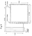
- FIG. 5 shows a frame structure of an STS-1 signal frame employed in the optical transmission system, i.e., a synchronous optical network (SONET).
- the STS-1 has a frame 60 composed of 90 bytes X 9 rows. Of these 90 bytes X 9 rows, 3 bytes X 9 rows constitute a transport overhead 61 that contains data for supervision and maintenance, and which is removed when dropped by the ADM.
- the remaining 87 bytes X 9 rows serve as a synchronous payload envelope (SPE) that comprises a path overhead 63 of 1 byte X 9 rows and payloads (transmitted information) 62 of 86 bytes X 9 rows.
- the path overhead 63 contains the byte C2.
- FIG. 6 is a detailed diagram of the path overhead 63.
- the byte C2 corresponds to a signal label C2 64 which is the third byte from the upper end of the path overhead 63.
- the signal label 64 is a region where a code representing the format of data mapped for payloads 62 is added. If the code added to the signal label 64 is an unequipped code "00000000", this indicates that path terminating equipment is connected but that no path connection is provided. Any other code, which is not "00000000,” to be added to the byte C2 is referred to as an equipped code.
- Other bytes than the byte C2 in the path overhead 63 will not be described in detail as they have no direct bearing on the present invention.
- the linear ADM described in the above embodiment has a cross-connect function of the time slot assignment (TSA) type.
- TSA time slot assignment
- TSI time slot interchange
Landscapes
- Engineering & Computer Science (AREA)
- Computer Networks & Wireless Communication (AREA)
- Signal Processing (AREA)
- Time-Division Multiplex Systems (AREA)
- Optical Communication System (AREA)
- Data Exchanges In Wide-Area Networks (AREA)
Claims (15)
- Leitweglenkungssystem für einen linearen Einfügungs-Ausblendungs-Multiplexer (add-drop multiplexer) mit einem ersten Ausblendungsschalter (10), der mit einer ersten Übertragungsleitung verbunden ist, einem zweiten Ausblendungsschalter (40), der mit einer zweiten Übertragungsleitung verbunden ist, und einem Kanalschalter (50) für niedrigere Ebenen, der mit dem ersten Ausblendungsschalter (10) und dem zweiten Ausblendungsschalter (40) verbunden ist, mit:- einem ersten Auswahlschalter (11), der in dem ersten Ausblendungsschalter (10) vorgesehen ist, um einen einer Vielzahl von Kanälen auszuwählen, die mit der ersten Übertragungsleitung verbunden sind, und ein erstes, über den ausgewählten Kanal übertragenes Signal auszugeben;- einem zweiten Auswahlschalter (41), der in dem zweiten Ausblendungsschalter (40) vorgesehen ist, um einen einer Vielzahl von Kanälen auszuwählen, die mit der zweiten Übertragungsleitung verbunden sind, und ein zweites, über den ausgewählten Kanal übertragenes Signal auszugeben;gekennzeichnet durch- einen ersten Selektor (12), der in dem ersten Ausblendungsschalter (10) vorgesehen und mit dem ersten Auswahlschalter (11) gekoppelt ist, um selektiv das erste, von dem ersten Auswahlschalter (11) übertragene Signal auszugeben und zu sperren; und- einen zweiten Selektor (42), der in dem zweiten Ausblendungsschalter (40) vorgesehen und mit dem zweiten Auswahlschalter (41) gekoppelt ist, um das zweite, von dem zweiten Auswahlschalter (41) übertragene Signal zu sperren, wenn der erste Selektor (12) das erste Signal ausgibt, und um das zweite Signal auszugeben, wenn der erste Selektor (12) das erste Signal sperrt; und- Ausgabeeinrichtungen, die in dem Kanalschalter (50) vorgesehen sind, um das von den ersten (12) und zweiten (42) Selektoren übertragene erste und zweite Signal an einen Sender/Empfänger (70) für niedrigere Signalebenen auszugeben.
- Leitweglenkungssystem nach Anspruch 1, dadurch gekennzeichnet, daß- das Leitweglenkungssystem mit einer externen Quelle (2) gekoppelt ist, ferner einschließend Steuereinrichtungen (1), die von der externen Quelle (2) Befehle empfangen können, und welche mit den ersten (10) und zweiten (40) Auswahlschaltern verbunden sind, um die ersten und zweiten Auswahlschalter zu steuern, die Kanäle auszuwählen.
- Leitweglenkungssystem nach Anspruch 1, dadurch gekennzeichnet, daß- das Leitweglenkungssystem mit einer externen Quelle (2) gekoppelt ist, ferner einschließend Steuereinrichtungen (1), die von der externen Quelle (2) Befehle empfangen können, und die mit den ersten und zweiten Selektoren (12, 42) verbunden sind, um die ersten und zweiten Selektoren (12, 42) zu steuern, selektiv die ersten und zweiten Signale auszugeben und zu sperren.
- Leitweglenkungssystem nach Anspruch 1, dadurch gekennzeichnet, daß- der erste Auswahlschalter (11) Einrichtungen zum Ausgeben eines dritten, über den ausgewählten Kanal übertragenen Signals und eines vierten Signals (C2), dessen sämtliche Datenbits auf 0 gesetzt sind, umfaßt,- der erste Selektor (12) Einrichtungen zum Auswählen und Ausgeben eines der dritten und vierten Signale als das erste Signal umfaßt,- der zweite Auswahlschalter (41) Einrichtungen zum Ausgeben eines fünften, über den ausgewählten Kanal übertragenen Signals und eines sechsten Signals umfaßt, dessen sämtliche Datenbits auf 0 gesetzt sind, und- der zweite Selektor (42) Einrichtungen zum Ausgeben, als das zweite Signal, des sechsten Signals, wenn der erste Selektor (12) das dritte Signal ausgibt, und des fünften Signals, wenn der erste Selektor (12) das vierte Signal ausgibt, umfaßt.
- Leitweglenkungssystem nach Anspruch 1, dadurch gekennzeichnet, daß die Ausgabeeinrichtung (51) ein ODER-Gatter umfaßt.
- Leitweglenkungssystem nach Anspruch 1, dadurch gekennzeichnet, daß jedes der Signale von einem SONET STS-1 Rahmen ist.
- Leitweglenkungssystem nach Anspruch 6, dadurch gekennzeichnet, daß die Ausgabeeinrichtung Einrichtungen zum Auswählen und Ausgeben eines der ersten und zweiten Signale, die von den ersten und zweiten Selektoren ausgegeben werden, umfaßt, welches einen ausgestatteten Code aufweist, das einem Byte C2 des SONET STS-1 Rahmens zugefügt ist.
- Leitweglenkungssystem nach Anspruch 7, dadurch gekennzeichnet, daß der ausgestattete Code nicht dasselbe ist wie ein nicht ausgestatteter Code, in welchem sämtliche Bits 0 sind.
- Leitweglenkungssystem nach Anspruch 1, gekennzeichnet durch Demultiplexer 3, 6, die mit den ersten bzw. zweiten Übertragungsleitungen und den ersten bzw. zweiten Auswahlschaltern (11, 41) verbunden sind, um gedemultiplexte Ausgangssignale an die ersten bzw. zweiten Auswahlschalter (11, 41) anzulegen.
- Leitweglenkungssystem nach Anspruch 1, dadurch gekennzeichnet, daß der lineare Einfügungs-/Ausblendungsmultiplexer eine Kreuzverbindungsfunktion aufweist.
- Leitweglenkungssystem nach Anspruch 1, dadurch gekennzeichnet, daß- der erste Auswahlschalter (11) eine Vielzahl von ersten Auswahlschaltern umfaßt, und der erste Selektor (12) eine Vielzahl von ersten Selektoren umfaßt,- die Vielzahl von ersten Auswahlschaltern und die Vielzahl von ersten Selektoren als eine einzelne Blockeinheit zusammengesetzt sind,- der zweite Auswahlschalter (41) eine Vielzahl von zweiten Auswahlschaltern umfaßt, und der zweite Selektor (42) eine Vielzahl von zweiten Selektoren umfaßt,- die Vielzahl von zweiten Auswahlschaltern und die Vielzahl von zweiten Selektoren als eine einzelne Blockeinheit zusammengesetzt sind,- das Leitweglenkungssystem mit einer externen Quelle verbunden ist und ferner einschließt:- Steuerleitungen, die mit der externen Quelle verbunden sind; und- Steuereinrichtungen (1), die von der externen Quelle Befehle empfangen können, und die mit den Blockeinheiten über jeweilige Steuerleitungen verbunden sind, um die Blockeinheiten zu steuern, die Kanäle als Reaktion auf ein Auswahlsignal von der Steuereinrichtung auszuwählen.
- Leitweglenkungssystem nach Anspruch 11, dadurch gekennzeichnet, daß- die Steuereinrichtung (1) Einrichtungen zum Aufbauen von Pfaden jeweils für die Blockeinheiten umfaßt.
- Leitweglenkungssystem nach Anspruch 11 oder 12, gekennzeichnet durch Einfügungsschalter (20, 30) zum Auswählen von Einfügungskanälen von den Kanälen und Durchgangskanälen.
- Leitweglenkungssystem nach Anspruch 13, dadurch gekennzeichnet, daß- das Leitweglenkungssystem mit einer externen Quelle (2) gekoppelt ist, ferner einschließend Steuereinrichtungen (1), die von der externen Quelle Befehle empfangen können, und mit den Einfügungsschaltern (20, 30) verbunden sind, um die Einfügungsschalter (20, 30) zu steuern, die Einfügungskanäle auszuwählen.
- Leitweglenkungssystem für einen linearen Einfügungs-/Ausblendungsmultiplexer, der mit ersten und zweiten Übertragungsleitungen verbunden ist, mit:- einem ersten Ausblendungsschalter (10), der mit der ersten Ubertagungsleitung verbunden und als einzelne Blockeinheit gebildet ist; wobei der erste Ausblendungsschalter einschließt:- erste Auswahlschalter (11), von denen jeder angepaßt ist, einen entsprechenden einer Vielzahl von mit der ersten Übertragungsleitung verbundenen Kanälen auszuwählen und ein über den ausgewählten Kanal übertragenes, erstes Signal auszugeben; und- einen zweiten Ausblendungsschalter (40), der als einzelne Blockeinheit gebildet ist, wobei der zweite Ausblendungsschalter einschließt:- zweite Auswahlschalter (41), von denen jeder angepaßt ist, einen entsprechenden einer Vielzahl von mit der zweiten Übertragungsleitung verbundenen Kanälen auszuwählen und ein zweites, über den ausgewählten Kanal übertragenes Signal auszugeben;dadurch gekennzeichnet, daß- der erste Ausblendungsschalter erste Selektoren (12) einschließt, die jeweils mit den ersten Auswahlschaltern (11) gekoppelt sind, wobei jeder der ersten Selektoren (12) angepaßt ist, selektiv das erste, von dem entsprechenden der ersten Auswahlschalter (11) übertragene Signal selektiv auszugeben und zu sperren; und- der zweite Ausblendungsschalter zweite Selektoren (42) einschließt, die jeweils mit den zweiten Auswahlschaltern (41) gekoppelt sind, wobei jeder der zweiten Selektoren (42) angepaßt ist, das zweite, von dem entsprechenden der zweiten Auswahlschalter (41) übertragene Signal zu sperren, wenn ein entsprechender erster Selektor (12) das erste Signal ausgibt, und das zweite Signal auszugeben, wenn der entsprechende erste Selektor (12) das erste Signal sperrt; und- durch einen Kanalschalter (50), der Ausgabeeinrichtungen zum Ausgeben der ersten und zweiten, von den ersten und zweiten Selektoren (12, 42) übertragenen Signale einschließt.
Applications Claiming Priority (2)
| Application Number | Priority Date | Filing Date | Title |
|---|---|---|---|
| JP4999291 | 1991-03-15 | ||
| JP49992/91 | 1991-03-15 |
Publications (3)
| Publication Number | Publication Date |
|---|---|
| EP0503474A2 EP0503474A2 (de) | 1992-09-16 |
| EP0503474A3 EP0503474A3 (en) | 1993-07-21 |
| EP0503474B1 true EP0503474B1 (de) | 1997-07-02 |
Family
ID=12846509
Family Applications (1)
| Application Number | Title | Priority Date | Filing Date |
|---|---|---|---|
| EP92103752A Expired - Lifetime EP0503474B1 (de) | 1991-03-15 | 1992-03-05 | Leitweglenkungssystem für Linearmultiplexer mit Einfügung und Ausblendung von Kanälen |
Country Status (4)
| Country | Link |
|---|---|
| US (1) | US5311501A (de) |
| EP (1) | EP0503474B1 (de) |
| CA (1) | CA2063047C (de) |
| DE (1) | DE69220593T2 (de) |
Families Citing this family (23)
| Publication number | Priority date | Publication date | Assignee | Title |
|---|---|---|---|---|
| GB9127116D0 (en) * | 1991-12-20 | 1992-02-19 | Jahromi Fazlollah R | Interconnecting communications networks |
| US5524113A (en) * | 1993-08-30 | 1996-06-04 | Washington University | ATM switch interface |
| JP3226393B2 (ja) * | 1993-09-20 | 2001-11-05 | 富士通株式会社 | パス・プロテクション・スイッチ・リング・システム |
| JP3082554B2 (ja) * | 1994-01-11 | 2000-08-28 | 株式会社日立製作所 | セルフヒーリングリングスイッチ |
| GB9401430D0 (en) * | 1994-01-26 | 1994-03-23 | Plessey Telecomm | Switching system for a telecommunications system |
| JP3290534B2 (ja) * | 1994-03-18 | 2002-06-10 | 富士通株式会社 | パスプロテクションスイッチ装置 |
| US5493565A (en) * | 1994-08-10 | 1996-02-20 | Dsc Communications Corporation | Grooming device for streamlining a plurality of input signal lines into a grouped set of output signals |
| KR0129608B1 (ko) * | 1994-12-21 | 1998-04-14 | 양승택 | 분기 결합 제어장치 |
| JP3442180B2 (ja) * | 1995-02-23 | 2003-09-02 | 富士通株式会社 | アド・ドロップ・マルチプレクス装置 |
| JP3432958B2 (ja) * | 1995-07-21 | 2003-08-04 | 富士通株式会社 | 光伝送システム及び伝送路切替制御方法 |
| US6876624B1 (en) * | 1996-01-30 | 2005-04-05 | Hitachi, Ltd. | Multiplex conversion unit |
| JP3479926B2 (ja) * | 1996-03-06 | 2003-12-15 | 富士通株式会社 | Adm装置 |
| JP4105233B2 (ja) * | 1996-10-10 | 2008-06-25 | ティコ テレコミュニケーションズ(ユーエス) インコーポレイティド | 複数の分岐ユニットからの挿入/抜き出し光信号ラインを結合する方法及び装置 |
| JP3102471B2 (ja) * | 1997-01-31 | 2000-10-23 | 日本電気株式会社 | 信号切替方法 |
| CN1076914C (zh) * | 1997-05-17 | 2001-12-26 | 华为技术有限公司 | 光同步数字传输设备的分插复用器 |
| US6181676B1 (en) * | 1998-01-30 | 2001-01-30 | Nortel Networks Limited | System protection switching |
| US6529303B1 (en) | 1998-03-05 | 2003-03-04 | Kestrel Solutions, Inc. | Optical communications networks utilizing frequency division multiplexing |
| US6452945B1 (en) * | 1998-03-05 | 2002-09-17 | Kestrel Solutions, Inc. | Electrical add-drop multiplexing for optical communications networks utilizing frequency division multiplexing |
| RU2133080C1 (ru) * | 1998-05-19 | 1999-07-10 | Военная академия связи | Автоматическое устройство обхода для сетей связи |
| US6721508B1 (en) | 1998-12-14 | 2004-04-13 | Tellabs Operations Inc. | Optical line terminal arrangement, apparatus and methods |
| JP2000216802A (ja) * | 1999-01-22 | 2000-08-04 | Nec Corp | マルチアクセス伝送装置及びマルチアクセス伝送方法 |
| US20020039211A1 (en) * | 1999-09-24 | 2002-04-04 | Tian Shen | Variable rate high-speed input and output in optical communication networks |
| JP4866942B2 (ja) * | 2009-07-09 | 2012-02-01 | 富士通テレコムネットワークス株式会社 | 伝送装置、伝送制御方法およびosc処理装置 |
Family Cites Families (11)
| Publication number | Priority date | Publication date | Assignee | Title |
|---|---|---|---|---|
| JPS5689150A (en) * | 1979-12-20 | 1981-07-20 | Hitachi Ltd | Line control method for duplex data highway system |
| US4434485A (en) * | 1980-11-13 | 1984-02-28 | Rockwell International Corporation | Drop and insert channel bank with reduced channel units |
| JPS61247141A (ja) * | 1985-04-25 | 1986-11-04 | Toshiba Corp | 中継機能を備えた時分割多重通信装置 |
| US4667319A (en) * | 1985-07-29 | 1987-05-19 | Gte Sprint Communications Corporation | Digital repeater with 3-way branching of service channels |
| CA1321001C (en) * | 1988-02-04 | 1993-08-03 | Nec Corporation | Transmission line switching system |
| JP2564375B2 (ja) * | 1988-09-28 | 1996-12-18 | 株式会社日立製作所 | 分岐挿入型多重変換装置 |
| US4967405A (en) * | 1988-12-09 | 1990-10-30 | Transwitch Corporation | System for cross-connecting high speed digital SONET signals |
| US4964095A (en) * | 1989-05-12 | 1990-10-16 | Alcatel Na, Inc. | Data communication bypass apparatus and method |
| US5003531A (en) * | 1989-08-11 | 1991-03-26 | Infotron Systems Corporation | Survivable network using reverse protection ring |
| JPH0795706B2 (ja) * | 1989-10-18 | 1995-10-11 | 富士通株式会社 | 信号分岐方法 |
| US5179548A (en) * | 1991-06-27 | 1993-01-12 | Bell Communications Research, Inc. | Self-healing bidirectional logical-ring network using crossconnects |
-
1992
- 1992-02-21 US US07/838,679 patent/US5311501A/en not_active Expired - Lifetime
- 1992-03-05 EP EP92103752A patent/EP0503474B1/de not_active Expired - Lifetime
- 1992-03-05 DE DE69220593T patent/DE69220593T2/de not_active Expired - Fee Related
- 1992-03-13 CA CA002063047A patent/CA2063047C/en not_active Expired - Fee Related
Also Published As
| Publication number | Publication date |
|---|---|
| US5311501A (en) | 1994-05-10 |
| EP0503474A2 (de) | 1992-09-16 |
| DE69220593D1 (de) | 1997-08-07 |
| DE69220593T2 (de) | 1997-11-27 |
| CA2063047A1 (en) | 1992-09-16 |
| CA2063047C (en) | 1997-08-19 |
| EP0503474A3 (en) | 1993-07-21 |
Similar Documents
| Publication | Publication Date | Title |
|---|---|---|
| EP0503474B1 (de) | Leitweglenkungssystem für Linearmultiplexer mit Einfügung und Ausblendung von Kanälen | |
| US5278824A (en) | Dual hubbing in a bidirectional line-switched ring transmission system | |
| CA2130067C (en) | Ring interworking between bidirectional line-switched ring transmission systems | |
| US6707789B1 (en) | Flexible SONET ring with integrated cross-connect system | |
| EP0654922B1 (de) | Kommunikationssystem bestehend aus miteinander verbundenen, leitungsgeschalteten und weggeschalteten Ringübertragungssystemen | |
| EP0590872B1 (de) | Anlage und Verfahren zum selektiven tributären Schalten in einem bidirektionellen Ringvermittlungssystem | |
| US5440540A (en) | Ring interworking between a bidirectional line-switched ring transmission system and another ring transmission system | |
| EP0654923B1 (de) | Kommunikationssystem bestehend aus miteinander verbundenen, weggeschaltenen Ringübertragungssystemen | |
| US7386012B2 (en) | Multiplex transmission apparatuses, multiplex transmission networks, and operation method therefor | |
| US6049525A (en) | Terminal multiplexer and method of constructing the terminal multiplexer | |
| EP0217490B1 (de) | Übertragungssystem mit einer Schutzumschaltung unter Benützung von Kanalkennzeichnungen und individuellen Wahlschaltern | |
| US6201788B1 (en) | Transmission device and system having the same | |
| US5452307A (en) | Data multiplexing system having at least one low-speed interface circuit connected to a bus | |
| EP0638216B1 (de) | Querverbindungsarchitektur mit zeit- und raumkoppelgruppen für sdh-signale | |
| EP0085558A2 (de) | Überwachung von automatischen Vermittlungssystemen | |
| US6404734B1 (en) | Scalable network restoration device | |
| JPH0758808A (ja) | クロスコネクト用インタフェースおよび装置 | |
| US7075952B1 (en) | Multiplexing in a PDH telecommunications network | |
| US5493432A (en) | Optical communication system | |
| US6839319B2 (en) | Office recognition method in ring network | |
| EP0986924B1 (de) | Kreuzverbindungselement als switch-router und dezentralisiertes management in einem datenübertragungsnetz im sternkonfiguration | |
| US5761207A (en) | Multiplex communication system using variable multiframe format | |
| KR100223366B1 (ko) | 데이터 통신채널 선택회로 | |
| KR100284010B1 (ko) | 링형 망 결합을 위한 광가입자 전송장치에서의 타임 슬롯 스위칭 장치 | |
| JPH0517760B2 (de) |
Legal Events
| Date | Code | Title | Description |
|---|---|---|---|
| PUAI | Public reference made under article 153(3) epc to a published international application that has entered the european phase |
Free format text: ORIGINAL CODE: 0009012 |
|
| AK | Designated contracting states |
Kind code of ref document: A2 Designated state(s): DE FR GB |
|
| PUAL | Search report despatched |
Free format text: ORIGINAL CODE: 0009013 |
|
| AK | Designated contracting states |
Kind code of ref document: A3 Designated state(s): DE FR GB |
|
| 17P | Request for examination filed |
Effective date: 19930830 |
|
| 17Q | First examination report despatched |
Effective date: 19960119 |
|
| GRAG | Despatch of communication of intention to grant |
Free format text: ORIGINAL CODE: EPIDOS AGRA |
|
| GRAH | Despatch of communication of intention to grant a patent |
Free format text: ORIGINAL CODE: EPIDOS IGRA |
|
| GRAH | Despatch of communication of intention to grant a patent |
Free format text: ORIGINAL CODE: EPIDOS IGRA |
|
| GRAA | (expected) grant |
Free format text: ORIGINAL CODE: 0009210 |
|
| AK | Designated contracting states |
Kind code of ref document: B1 Designated state(s): DE FR GB |
|
| REF | Corresponds to: |
Ref document number: 69220593 Country of ref document: DE Date of ref document: 19970807 |
|
| ET | Fr: translation filed | ||
| PLBE | No opposition filed within time limit |
Free format text: ORIGINAL CODE: 0009261 |
|
| STAA | Information on the status of an ep patent application or granted ep patent |
Free format text: STATUS: NO OPPOSITION FILED WITHIN TIME LIMIT |
|
| 26N | No opposition filed | ||
| PGFP | Annual fee paid to national office [announced via postgrant information from national office to epo] |
Ref country code: GB Payment date: 20000301 Year of fee payment: 9 |
|
| PGFP | Annual fee paid to national office [announced via postgrant information from national office to epo] |
Ref country code: DE Payment date: 20000306 Year of fee payment: 9 |
|
| PGFP | Annual fee paid to national office [announced via postgrant information from national office to epo] |
Ref country code: FR Payment date: 20000310 Year of fee payment: 9 |
|
| PG25 | Lapsed in a contracting state [announced via postgrant information from national office to epo] |
Ref country code: GB Free format text: LAPSE BECAUSE OF NON-PAYMENT OF DUE FEES Effective date: 20010305 |
|
| GBPC | Gb: european patent ceased through non-payment of renewal fee |
Effective date: 20010305 |
|
| PG25 | Lapsed in a contracting state [announced via postgrant information from national office to epo] |
Ref country code: FR Free format text: LAPSE BECAUSE OF NON-PAYMENT OF DUE FEES Effective date: 20011130 |
|
| REG | Reference to a national code |
Ref country code: FR Ref legal event code: ST |
|
| PG25 | Lapsed in a contracting state [announced via postgrant information from national office to epo] |
Ref country code: DE Free format text: LAPSE BECAUSE OF NON-PAYMENT OF DUE FEES Effective date: 20020101 |