EP0503679B1 - Lesevorrichtung für optische Karte - Google Patents
Lesevorrichtung für optische Karte Download PDFInfo
- Publication number
- EP0503679B1 EP0503679B1 EP92104506A EP92104506A EP0503679B1 EP 0503679 B1 EP0503679 B1 EP 0503679B1 EP 92104506 A EP92104506 A EP 92104506A EP 92104506 A EP92104506 A EP 92104506A EP 0503679 B1 EP0503679 B1 EP 0503679B1
- Authority
- EP
- European Patent Office
- Prior art keywords
- data
- track
- reading
- read
- command
- Prior art date
- Legal status (The legal status is an assumption and is not a legal conclusion. Google has not performed a legal analysis and makes no representation as to the accuracy of the status listed.)
- Expired - Lifetime
Links
Images


Classifications
-
- G—PHYSICS
- G06—COMPUTING OR CALCULATING; COUNTING
- G06K—GRAPHICAL DATA READING; PRESENTATION OF DATA; RECORD CARRIERS; HANDLING RECORD CARRIERS
- G06K7/00—Methods or arrangements for sensing record carriers, e.g. for reading patterns
- G06K7/10—Methods or arrangements for sensing record carriers, e.g. for reading patterns by electromagnetic radiation, e.g. optical sensing; by corpuscular radiation
- G06K7/14—Methods or arrangements for sensing record carriers, e.g. for reading patterns by electromagnetic radiation, e.g. optical sensing; by corpuscular radiation using light without selection of wavelength, e.g. sensing reflected white light
-
- G—PHYSICS
- G11—INFORMATION STORAGE
- G11B—INFORMATION STORAGE BASED ON RELATIVE MOVEMENT BETWEEN RECORD CARRIER AND TRANSDUCER
- G11B11/00—Recording on or reproducing from the same record carrier wherein for these two operations the methods are covered by different main groups of groups G11B3/00 - G11B7/00 or by different subgroups of group G11B9/00; Record carriers therefor
- G11B11/10—Recording on or reproducing from the same record carrier wherein for these two operations the methods are covered by different main groups of groups G11B3/00 - G11B7/00 or by different subgroups of group G11B9/00; Record carriers therefor using recording by magnetic means or other means for magnetisation or demagnetisation of a record carrier, e.g. light induced spin magnetisation; Demagnetisation by thermal or stress means in the presence or not of an orienting magnetic field
- G11B11/105—Recording on or reproducing from the same record carrier wherein for these two operations the methods are covered by different main groups of groups G11B3/00 - G11B7/00 or by different subgroups of group G11B9/00; Record carriers therefor using recording by magnetic means or other means for magnetisation or demagnetisation of a record carrier, e.g. light induced spin magnetisation; Demagnetisation by thermal or stress means in the presence or not of an orienting magnetic field using a beam of light or a magnetic field for recording by change of magnetisation and a beam of light for reproducing, i.e. magneto-optical, e.g. light-induced thermomagnetic recording, spin magnetisation recording, Kerr or Faraday effect reproducing
- G11B11/10502—Recording on or reproducing from the same record carrier wherein for these two operations the methods are covered by different main groups of groups G11B3/00 - G11B7/00 or by different subgroups of group G11B9/00; Record carriers therefor using recording by magnetic means or other means for magnetisation or demagnetisation of a record carrier, e.g. light induced spin magnetisation; Demagnetisation by thermal or stress means in the presence or not of an orienting magnetic field using a beam of light or a magnetic field for recording by change of magnetisation and a beam of light for reproducing, i.e. magneto-optical, e.g. light-induced thermomagnetic recording, spin magnetisation recording, Kerr or Faraday effect reproducing characterised by the transducing operation to be executed
- G11B11/10515—Reproducing
-
- G—PHYSICS
- G11—INFORMATION STORAGE
- G11B—INFORMATION STORAGE BASED ON RELATIVE MOVEMENT BETWEEN RECORD CARRIER AND TRANSDUCER
- G11B11/00—Recording on or reproducing from the same record carrier wherein for these two operations the methods are covered by different main groups of groups G11B3/00 - G11B7/00 or by different subgroups of group G11B9/00; Record carriers therefor
- G11B11/10—Recording on or reproducing from the same record carrier wherein for these two operations the methods are covered by different main groups of groups G11B3/00 - G11B7/00 or by different subgroups of group G11B9/00; Record carriers therefor using recording by magnetic means or other means for magnetisation or demagnetisation of a record carrier, e.g. light induced spin magnetisation; Demagnetisation by thermal or stress means in the presence or not of an orienting magnetic field
- G11B11/105—Recording on or reproducing from the same record carrier wherein for these two operations the methods are covered by different main groups of groups G11B3/00 - G11B7/00 or by different subgroups of group G11B9/00; Record carriers therefor using recording by magnetic means or other means for magnetisation or demagnetisation of a record carrier, e.g. light induced spin magnetisation; Demagnetisation by thermal or stress means in the presence or not of an orienting magnetic field using a beam of light or a magnetic field for recording by change of magnetisation and a beam of light for reproducing, i.e. magneto-optical, e.g. light-induced thermomagnetic recording, spin magnetisation recording, Kerr or Faraday effect reproducing
- G11B11/10595—Control of operating function
-
- G—PHYSICS
- G11—INFORMATION STORAGE
- G11B—INFORMATION STORAGE BASED ON RELATIVE MOVEMENT BETWEEN RECORD CARRIER AND TRANSDUCER
- G11B19/00—Driving, starting, stopping record carriers not specifically of filamentary or web form, or of supports therefor; Control thereof; Control of operating function ; Driving both disc and head
- G11B19/02—Control of operating function, e.g. switching from recording to reproducing
-
- G—PHYSICS
- G11—INFORMATION STORAGE
- G11B—INFORMATION STORAGE BASED ON RELATIVE MOVEMENT BETWEEN RECORD CARRIER AND TRANSDUCER
- G11B19/00—Driving, starting, stopping record carriers not specifically of filamentary or web form, or of supports therefor; Control thereof; Control of operating function ; Driving both disc and head
- G11B19/20—Driving; Starting; Stopping; Control thereof
-
- G—PHYSICS
- G11—INFORMATION STORAGE
- G11B—INFORMATION STORAGE BASED ON RELATIVE MOVEMENT BETWEEN RECORD CARRIER AND TRANSDUCER
- G11B20/00—Signal processing not specific to the method of recording or reproducing; Circuits therefor
- G11B20/10—Digital recording or reproducing
- G11B20/18—Error detection or correction; Testing, e.g. of drop-outs
- G11B20/1833—Error detection or correction; Testing, e.g. of drop-outs by adding special lists or symbols to the coded information
-
- G—PHYSICS
- G11—INFORMATION STORAGE
- G11B—INFORMATION STORAGE BASED ON RELATIVE MOVEMENT BETWEEN RECORD CARRIER AND TRANSDUCER
- G11B7/00—Recording or reproducing by optical means, e.g. recording using a thermal beam of optical radiation by modifying optical properties or the physical structure, reproducing using an optical beam at lower power by sensing optical properties; Record carriers therefor
- G11B7/002—Recording, reproducing or erasing systems characterised by the shape or form of the carrier
- G11B7/0033—Recording, reproducing or erasing systems characterised by the shape or form of the carrier with cards or other card-like flat carriers, e.g. flat sheets of optical film
-
- G—PHYSICS
- G11—INFORMATION STORAGE
- G11B—INFORMATION STORAGE BASED ON RELATIVE MOVEMENT BETWEEN RECORD CARRIER AND TRANSDUCER
- G11B7/00—Recording or reproducing by optical means, e.g. recording using a thermal beam of optical radiation by modifying optical properties or the physical structure, reproducing using an optical beam at lower power by sensing optical properties; Record carriers therefor
- G11B7/004—Recording, reproducing or erasing methods; Read, write or erase circuits therefor
- G11B7/005—Reproducing
Definitions
- optical card is used herein to mean a card on which data can be recorded and reproduced optically, or one on which data can be recorded and reproduced photomagnetically.
- Figure 6 shows a known optical card 40 and includes an enlarged portion showing data tracks, on which data are recorded and reproduced optically by a card reader/writer.
- optical card 40 has a data recording area 41, within which a number of tracks 43 are separated from each other by track guides 42. Data are recorded on tracks 43 in the form of pits 44.
- optical cards typically have a recording capacity of around two megabytes.
- the recording of data on an optical card entails a number of coding operations, including error detection prior to recording, error correction and data interleave. To read the data from the card, then, it must first be decoded, and only one data track can be decoded at a time.
- Figures 7 and 8 show the timing of the card-feed operation in relation to the read and decode operations in an existing device for recording and reproducing data on optical cards. These figures reflect the prior art the preambles of claims 1 and 10 are based on.
- Figure 7 shows the timing which exists after the card is conveyed back to its starting point. Data will be read only while the card is being fed forward (forward conveyance).
- the optical card is conveyed forwardly by the feed device in the direction in which its tracks are oriented (Direction X in Figure 6).
- the optical head which reads the data off the card is conveyed in the direction orthogonal to that of the card's movement (Direction Y in Figure 6), to access the specified track.
- the optical card is conveyed in a forward direction when a read command is output by the CPU.
- the data are read from the specified track by the optical head.
- the decoding operation is begun. While decoding is in process, the optical card is then conveyed in the reverse direction. The amount of time it takes to reverse is determined by how fast the card-feed device conveys the marginal portion of card 40 which surrounds recording area 41 and how long it takes for the conveyor motor of the card-feed device to come to a halt and start up in reverse.
- the newly decoded data are transmitted to the CPU as a response. If data are being continuously reproduced over a number of tracks, a read command for the next track will be transmitted by the CPU as soon it receives the response. However, at this moment the card feed device is in the midst of conveying the card in the reverse direction. Therefore, before the reading of the data on the next track can begin, there is an unavoidable wait (waiting time) while the reverse feed of the card is completed and the direction of feed is changed.
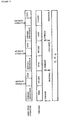
- Figure 8 shows the timing relationship between the card-feed and the various operations when the card is fed in two directions and the data are read off the card during both forward movement (forward conveyance) and reverse movement (reverse conveyance).
- the optical card is conveyed in a forward direction when a read command is output by the CPU.
- the data are read from a first specified track by the optical head.
- the decoding operation is begun. While decoding is in process, the card-feed operation will be halted after the direction of card-feed has been reversed, and will remain stopped (stop time) until a read command for the next track is issued by the CPU.
- the newly decoded data are transmitted to the CPU as a response. If data are being continuously reproduced over a number of tracks, a read command for the next track will be transmitted by the CPU as soon as the response is received. This command will cause the optical card to be conveyed in the reverse direction and its data to be read and decoded exactly as before.
- One object of the invention is to provide an optical-card reader as defined in claim 1 and a method as defined in claim 10 which overcomes the problems of wasted time attendant known optical readers. It comprises reading means, memory means, decoder means, and controlling means.
- the controlling means operates to initiate a reading of a first specified track and the read track data is decoded as the controlling means initiates a reading of a second specified track, when a reading command requiring the reading of a plurality of data tracks is given.
- the first specified track is accessed by an optical head, and the data are read from that single track as the card is being conveyed. Once read, the data are stored in a read buffer.
- the reading and decoding of data are performed in parallel.
- the data in the succeeding track will be read as soon as the reading of the data in the earlier track has been completed.
- the decoding of the data in the preceding track is completed, the data in the next track will already have been partially or completely read.
- the decoded data with respect to the read command can be transmitted without delay. There is no need to delay data reading in order to synchronize it with the operation of the card-feed device, nor is there any need to halt the card-feed device while decoding is in process.
- read commands are issued intermittently, the reading of the data in the track indicated by the command will already be finished, and a response can be sent as soon as those data are decoded.
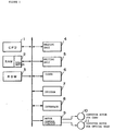
- FIG. 1 is a block diagram of the electrical organization of an optical-card recording and reproducing system constructed in accordance with the invention.
- the system comprises CPU 1, which oversees all operations; RAM 2, which stores the various data that are read; ROM 3, in which the operating program, constants and other necessary information are stored prior to the use of the device; data reading unit 4, which reads data off the optical card one track at a time; data writing unit 5, which writes data onto the optical card; coder 6, which codes the data which are to be written on the optical card; decoder 7, which decodes the data read off the optical card; interface 8, which connects the device to external equipment; and motor control circuit 9, which controls conveyor motor 10 in the card-feed device and conveyor motor 11 in the device which conveys an optical head for recording and reproduction.
- CPU 1 which oversees all operations
- RAM 2 which stores the various data that are read
- ROM 3 in which the operating program, constants and other necessary information are stored prior to the use of the device
- data reading unit 4 which reads data off the optical card one track at a
- Data reading unit 4 includes both the read circuit, which shapes the waveform of the read signal from the optical head (not shown) and converts it from an analog to a digital signal, and the circuit which controls this read circuit.
- Data writing unit 5 includes the DA converter circuit for data to be written in; the drive circuit for the optical head; and the control circuit for that drive circuit. Data reading unit 4 and data writing unit 5 also control the operation of motor control circuit 9.
- the functions of the control circuits for reading unit 4 and writing unit 5 as well as those of coder 6 and decoder 7 may be constructed either by hardware or by software. If software were chosen, a CPU would be provided for units 4, 5, 6 and 7. This CPU could serve all four units, or some might be served by CPU 1.
- RAM 2 contains the read buffer. The data read from one track by reading unit 4 are stored temporarily in this read buffer.
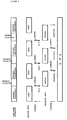
- Figure 2 shows the timing relationship between the movement of the optical card and the various operations of the Figure 1 system when the data are read off the card as it moves in both forward and reverse directions, and when a read command for the next track is issued by the CPU immediately after a response is received. Such a command indicates that succeeding tracks should be read in order, and it designates the next track to be read after every track.
- a read command for the second track is sent to reading unit 4.
- decoder 7 immediately begins decoding the data from the first track which are stored in the buffer.
- reading unit 4 directs that the direction of card-feed be reversed, the card is conveyed in the opposite direction, and the optical head accesses the next track.
- reading unit 4 reads the data from the second track.
- the reading of data from the second track by unit 4 and the decoding of the data in the buffer by decoder 7 are performed in parallel. If the decoding of the data from the first track is completed first, the decoded data are transmitted from decoder 7 to the CPU as a response.
- decoder 7 waits for the data from the second track to be accessed in the buffer. While it begins decoding these data, reading unit 4 is directed to read the data on the third track.
- Figure 3 shows the timing relationship between the travel of the optical card and the various operations of Figure 1 system when the data are read from the card during both its forward and reverse movement, and read commands for succeeding tracks are issued intermittently by the CPU in the intervals not required for the reading and decoding of a single track's data.
- a read command for the first of a succession of tracks is issued by the CPU to decoder 7.
- decoder 7 Upon receiving this command, decoder 7 sends a read command to reading unit 4, which begins to read the data.
- the first track which has been designated is accessed by the optical head, and the optical card is fed forward.
- reading unit 4 reads the data from one track.
- the data read from the first track are stored in the read buffer, and decoder 7 decodes them. Since read commands are being issued for successive tracks, decoder 7 immediately sends a read command for the second track to reading unit 4. In response to this read command, the optical card is conveyed in reverse in the reading unit, and the data are read from the second track.
- decoder 7 stands by. If the reading of the data on the second track is completed during this interval, these data are stored in the read buffer.
- the CPU will send the consecutive read command, which will be for the data on the third track.
- Decoder 7 will transmit a read command for the third track to reading unit 4, and will immediately begin decoding the data from the second track which are stored in the read buffer.
- reading unit 4 When reading unit 4 receives the read command, it will read the data from the third track as the card is being conveyed in reverse.
- the decoding of the data from the second track and the reading of the data from the third track are performed in parallel.
- the CPU response to that read command, the data from that track are decoded and immediately transmitted to the CPU.
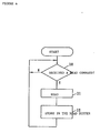
- Figure 4 shows the order of processing performed by reading unit 4 when it executes the operations shown in Figures 2 and 3.
- decoder 7 begins operation of reading unit 4 by issuing a read command to reading unit 4 for the data in a given track.
- the answer in Step 30 is "yes.”
- Reading unit 4 performs all the processing entailed in reading the data, including causing the optical head to access the specified track, causing the optical card to be fed forward or in reverse, and so on (Step 31).
- Step 32 When all the data have been read off this track, they are stored in the read buffer in RAM 2 (Step 32).
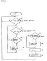
- Figure 5 shows the order of processing performed by decoder 7 when it executes the operations shown in Figures 2 and 3.
- a read command for track N (the number of the track designated by the CPU is N) is received from the CPU. (The answer in Step 20 is "yes.")
- the decoder checks whether there are any data previously read by reading unit 4 stored in the read buffer in RAM 2 (Step 21). If there are no data stored in the buffer, decoder 7 checks whether reading unit 4 is currently in the process of reading data (Step 22). If reading unit 4 is not reading data, decoder 7 sends it a read command for the data on track N (Step 23). If reading unit 4 is reading data, decoder 7 waits until the data reading has been completed. When reading unit 4 has read all the data, they are stored in read buffer 3.
- Step 21 If a command received from the CPU when data is stored or is being stored in the read buffer in RAM 2 (the answer in Step 21 is “yes”) turns out to be a read command for the succeeding track (the answer in Step 24 is "yes"), a read command for track N + 1 (the next track) is issued to reading unit 4.
- the data in the read buffer will immediately be decoded (Step 26).
- the decoded data are transmitted to the CPU (Step 27).
- a read command will be output by the CPU either immediately after the response or after some time has elapsed. In either case, decoder 7 checks again whether there are any data in the read buffer, and repeats the procedure outlined above. If the command received from the CPU is not a read command for the succeeding track, the processing in Step 25 is skipped.
Landscapes
- Engineering & Computer Science (AREA)
- Physics & Mathematics (AREA)
- Artificial Intelligence (AREA)
- General Health & Medical Sciences (AREA)
- Toxicology (AREA)
- Electromagnetism (AREA)
- Health & Medical Sciences (AREA)
- Computer Vision & Pattern Recognition (AREA)
- General Physics & Mathematics (AREA)
- Theoretical Computer Science (AREA)
- Signal Processing (AREA)
- Signal Processing For Digital Recording And Reproducing (AREA)
- Optical Recording Or Reproduction (AREA)
- Holo Graphy (AREA)
Claims (17)
- Leser für eine optische Karte mitLesemitteln (4) zum Lesen von auf einer bestimmten Spur (43) einer optischen Karte (40) aufgezeichneten Daten,Speichermitteln (2) zum Speichern von mit den Lesemitteln gelesenen Daten,Decodiermitteln (7) zum Decodieren von in den Speichermitteln gespeicherten gelesenen Daten,Steuermitteln (1) zum Steuern der Lesemittel, Speichermittel und Decodiermittel,dadurch gekennzeichnet, daß die Steuermittel so arbeiten, daß sie die Lesemittel (4) Daten von einer Spur der optischen Karte lesen lassen, während die Decodiermittel (7) in den Speichermitteln (2) gespeicherte Daten decodieren, die von einer anderen Spur der optischen Karte vorher gelesen worden sind.
- Leser für eine optische Karte nach Anspruch 1, wobei die Steuermittel (1) einen Kartenlesevorgang für eine bestimmte Spur in Gang setzen, indem sie einen Lesebefehl für die bestimmte Spur ausgeben, der auf die Lesemittel gekoppelt wird.
- Leser für eine optische Karte nach Anspruch 2, wobei der ausgegebene Lesebefehl von den Decodiermitteln (7) empfangen wird, welche ein Befehlssignal auf die Lesemittel (4) ausgeben, um einen Kartenlesevorgang der bestimmten Spur in Gang zu setzen.
- Leser für eine optische Karte nach Anspruch 3, wobei die Lesemittel (4) Daten aus der einen Spur mit einer Relativbewegung von Karte (40) und Lesemitteln (4) in einer ersten Transportierrichtung auslesen und die Lesemittel (4) die Daten aus der anderen Spur bei einer Relativbewegung von Karte (40) und Lesemitteln (4) in einer zweiten Transportierrichtung entgegengesetzt zur ersten Transportierrichtung auslesen.
- Leser für eine optische Karte nach Anspruch 5, wobei die Lesemittel (4) die relative Transportierrichtung der Karte während der Decodierung von vorher aus einer anderen Spur ausgelesenen Daten umkehren.
- Leser für eine optische Karte nach Anspruch 1, wobei die Decodiermittel (7) aufweisen: Mittel, die auf einen von den Steuermitteln (1) ausgegebenen Lesebefehl ansprechen, zum Lesen einer vorgeschriebenen Spur; Mittel zur Feststellung, ob irgendwelche vorher gelesene Spurdaten decodiert werden müssen; Mittel zur Feststellung, ob die Lesemittel gerade Daten von der optischen Karte lesen, wenn keine vorher gelesenen Spurdaten decodiert werden müssen; und Mittel zum Senden eines Lesebefehls für eine vorgeschriebene Spur an die Lesemittel, wenn die Lesemittel (4) gerade keine Daten lesen.
- Leser für eine optische Karte nach Anspruch 6, wobei die Decodiermittel (7) ferner Mittel, die auf eine Angabe ansprechen, daß vorher gelesene Daten decodiert werden müssen, zur Bestimmung, ob der Lesebefehl der Steuermittel für eine Spur bestimmt ist, welche in einer bestimmten Reihenfolge auf die vorher gelesene Spur folgt, und, falls dies so ist, zur Ausgabe eines Befehls an die Lesemittel, die nächste Spur in der Reihenfolge zu lesen, aufweisen.
- Leser für eine optische Karte nach Anspruch 7, wobei die Decodiermittel (7) die letzten gelesenen Spurdaten decodieren und die decodierten Daten an die Steuermittel senden, wenn der Lesebefehl der Steuermittel für eine Spur bestimmt ist, die nicht in einer bestimmten Reihenfolge auf eine zuletzt gelesene Spur folgt.
- Leser für eine optische Karte nach Anspruch 7, wobei die Decodiermittel (7) die gelesenen Daten der in numerischer Reihenfolge nächsten Spur decodieren.
- Verfahren zum Betreiben eines Lesers für eine optische Karte, wobei das Verfahren die Schritte desLesens von auf einer bestimmten Spur (43) einer optischen Karte (40) aufgezeichneten Daten,Speicherns der gelesenen Daten in Speichermitteln (2),Decodierens der in den Speichermitteln (2) gespeicherten gelesenen Daten aufweist,dadurch gekennzeichnet, daß Daten von einer Spur der optischen Karte gelesen werden, während vorher von einer anderen Spur der optischen Karte gelesene in den Speichermitteln gespeicherte Daten decodiert werden.
- Verfahren nach Anspruch 10, welches ferner den Schritt des Aufgebens von decodierten Daten auf Steuermittel aufweist.
- Verfahren nach Anspruch 10, wobei in der einen und anderen Spur enthaltene Daten Teil eines einzelnen Datensatzes bilden.
- Verfahren nach Anspruch 10, wobei das Lesen von Daten von der einen Spur durch einen Lesebefehl erfolgt, der von einem Steuergerät ausgegeben und an die Leseeinheit über einen Decodierer weitergegeben wird, welcher den Decodierschritt ausführt, und das Lesen von Daten von der anderen Spur durch einen weiteren Lesebefehl erfolgt, der direkt vom Decodierer ausgegeben wird.
- Verfahren nach Anspruch 10, wobei das Lesen von Daten von der einen Spur durch einen Lesebefehl erfolgt, der von einem Steuergerät ausgegeben und an die Leseeinheit über einen Decodierer weitergegeben wird, welcher den Decodierschritt durchführt, und das Lesen von Daten von der anderen Spur durch einen weiteren Lesebefehl erfolgt, der auch durch das Steuergerät ausgegeben und über den Decodierer an die Leseeinheit weitergegeben wird.
- Verfahren nach Anspruch 10, welches ferner die Schritte des Prüfens, wenn ein Lesebefehl für eine bestimmte Spur empfangen wird, ob Daten einer vorher gelesenen Spur gespeichert sind, wobei, wenn dies der Fall ist, das Verfahren ferner die Schritte des Feststellens, ob der ausgegebene Befehl für eine nächstnachfolgende Spur bestimmt ist, und, wenn dies der Fall ist, Absendens eines Lesebefehls zum Lesen der nächstnachfolgenden Spur an die Leseeinheit und nachfolgenden Decodierens der gespeicherten Daten der vorher gelesenen Spur aufweist.
- Verfahren nach Anspruch 15, wobei, wenn der ausgegebene Befehl nicht für die nächstnachfolgende Spur bestimmt ist, das Verfahren ferner das Decodieren der gespeicherten Daten der vorher gelesenen Spur aufweist.
- Verfahren nach Anspruch 16, wobei, wenn keine Daten einer vorher gelesenen Spur gespeichert sind, das Verfahren ferner das Bestimmen, ob eine Leseeinheit gerade Spuren der Karte liest, und, falls nicht, das Ausgeben eines Lesebefehls an die Leseeinheit für die bestimmte Spur aufweist.
Applications Claiming Priority (2)
| Application Number | Priority Date | Filing Date | Title |
|---|---|---|---|
| JP3074194A JPH04286726A (ja) | 1991-03-15 | 1991-03-15 | 光カードの再生装置および再生方法 |
| JP74194/91 | 1991-03-15 |
Publications (3)
| Publication Number | Publication Date |
|---|---|
| EP0503679A2 EP0503679A2 (de) | 1992-09-16 |
| EP0503679A3 EP0503679A3 (en) | 1993-01-13 |
| EP0503679B1 true EP0503679B1 (de) | 1997-07-09 |
Family
ID=13540129
Family Applications (1)
| Application Number | Title | Priority Date | Filing Date |
|---|---|---|---|
| EP92104506A Expired - Lifetime EP0503679B1 (de) | 1991-03-15 | 1992-03-16 | Lesevorrichtung für optische Karte |
Country Status (5)
| Country | Link |
|---|---|
| US (1) | US5308961A (de) |
| EP (1) | EP0503679B1 (de) |
| JP (1) | JPH04286726A (de) |
| AT (1) | ATE155276T1 (de) |
| DE (1) | DE69220695T2 (de) |
Families Citing this family (1)
| Publication number | Priority date | Publication date | Assignee | Title |
|---|---|---|---|---|
| JP4319984B2 (ja) * | 2002-09-02 | 2009-08-26 | セッテック インコーポレイテッド | 記録媒体複製用の複製装置、その方法、及びそのコンピュータプログラム |
Family Cites Families (4)
| Publication number | Priority date | Publication date | Assignee | Title |
|---|---|---|---|---|
| JPH0782421B2 (ja) * | 1985-12-04 | 1995-09-06 | キヤノン株式会社 | 情報記憶システムの情報処理方法 |
| US5008552A (en) * | 1987-02-12 | 1991-04-16 | Dai Nippon Insatsu Kabushiki Kaisha | Data recording and reproducing apparatus for an optical card |
| AU622626B2 (en) * | 1987-06-03 | 1992-04-16 | Sony Corporation | Method of processing data |
| US4958339A (en) * | 1988-01-07 | 1990-09-18 | Kabushiki Kaisha Toshiba | Optical card with increased data storage capacity and recording/reproducing apparatus therefor |
-
1991
- 1991-03-15 JP JP3074194A patent/JPH04286726A/ja active Pending
-
1992
- 1992-03-13 US US07/851,694 patent/US5308961A/en not_active Expired - Lifetime
- 1992-03-16 AT AT92104506T patent/ATE155276T1/de not_active IP Right Cessation
- 1992-03-16 DE DE69220695T patent/DE69220695T2/de not_active Expired - Fee Related
- 1992-03-16 EP EP92104506A patent/EP0503679B1/de not_active Expired - Lifetime
Also Published As
| Publication number | Publication date |
|---|---|
| EP0503679A2 (de) | 1992-09-16 |
| DE69220695T2 (de) | 1998-02-19 |
| JPH04286726A (ja) | 1992-10-12 |
| DE69220695D1 (de) | 1997-08-14 |
| ATE155276T1 (de) | 1997-07-15 |
| EP0503679A3 (en) | 1993-01-13 |
| US5308961A (en) | 1994-05-03 |
Similar Documents
| Publication | Publication Date | Title |
|---|---|---|
| US4442485A (en) | Dynamically buffered data transfer system for large capacity data source | |
| US5128810A (en) | Single disk emulation interface for an array of synchronous spindle disk drives | |
| US3761903A (en) | Redundant offset recording | |
| US4007448A (en) | Drive for connection to multiple controllers in a digital data secondary storage facility | |
| JP2522904B2 (ja) | 記憶媒体内に記憶された複数のデ―タブロックを読取り且つ処理するシステムおよび方法 | |
| NL8601437A (nl) | Sequentiele bufferinrichting. | |
| EP0503679B1 (de) | Lesevorrichtung für optische Karte | |
| US4864113A (en) | Information memory system for reading information from a moving recording medium | |
| EP0257594A2 (de) | Aufzeichnungsanordnung zum einmaligen Einschreiben von Daten für optisches Medium | |
| US4704641A (en) | Recovery of stored data from mutilated tape data blocks | |
| US5377056A (en) | Digital data tape reading device | |
| US4831243A (en) | Information memory apparatus for reading out information from a moving recording medium | |
| EP0084950A2 (de) | System zum Speichern von Daten mittels eines Videobandes | |
| EP0341850B1 (de) | Dokumentenlesegeräte | |
| JPH0737326A (ja) | 光ディスク装置 | |
| US5434715A (en) | Process and device for copying magnetic tapes containing both program material and control data | |
| JP2952029B2 (ja) | 光カード情報記録再生装置 | |
| US4991036A (en) | Moving data storage media mode/direction change optimization | |
| US5452458A (en) | Method of controlling a flexible disk controller | |
| JP2797991B2 (ja) | カートリッジ磁気テープのデータ検索方式およびデータ検索装置 | |
| JPS58114151A (ja) | 共通制御方式 | |
| JPH08263220A (ja) | データ入出力装置 | |
| JPS6043735A (ja) | 外部記憶装置 | |
| GB1574171A (en) | Disc memory system | |
| JPH0258768A (ja) | ディスク制御装置 |
Legal Events
| Date | Code | Title | Description |
|---|---|---|---|
| PUAI | Public reference made under article 153(3) epc to a published international application that has entered the european phase |
Free format text: ORIGINAL CODE: 0009012 |
|
| 17P | Request for examination filed |
Effective date: 19920413 |
|
| AK | Designated contracting states |
Kind code of ref document: A2 Designated state(s): AT BE CH DE DK ES FR GB GR IT LI MC NL PT SE |
|
| PUAL | Search report despatched |
Free format text: ORIGINAL CODE: 0009013 |
|
| AK | Designated contracting states |
Kind code of ref document: A3 Designated state(s): AT BE CH DE DK ES FR GB GR IT LI MC NL PT SE |
|
| 17Q | First examination report despatched |
Effective date: 19950811 |
|
| GRAG | Despatch of communication of intention to grant |
Free format text: ORIGINAL CODE: EPIDOS AGRA |
|
| GRAH | Despatch of communication of intention to grant a patent |
Free format text: ORIGINAL CODE: EPIDOS IGRA |
|
| GRAH | Despatch of communication of intention to grant a patent |
Free format text: ORIGINAL CODE: EPIDOS IGRA |
|
| GRAA | (expected) grant |
Free format text: ORIGINAL CODE: 0009210 |
|
| AK | Designated contracting states |
Kind code of ref document: B1 Designated state(s): AT BE CH DE DK ES FR GB GR IT LI MC NL PT SE |
|
| PG25 | Lapsed in a contracting state [announced via postgrant information from national office to epo] |
Ref country code: IT Free format text: LAPSE BECAUSE OF FAILURE TO SUBMIT A TRANSLATION OF THE DESCRIPTION OR TO PAY THE FEE WITHIN THE PRE;WARNING: LAPSES OF ITALIAN PATENTS WITH EFFECTIVE DATE BEFORE 2007 MAY HAVE OCCURRED AT ANY TIME BEFORE 2007. THE CORRECT EFFECTIVE DATE MAY BE DIFFERENT FROM THE ONE RECORDED.SCRIBED TIME-LIMIT Effective date: 19970709 Ref country code: LI Effective date: 19970709 Ref country code: BE Effective date: 19970709 Ref country code: CH Effective date: 19970709 Ref country code: FR Effective date: 19970709 Ref country code: GR Free format text: LAPSE BECAUSE OF FAILURE TO SUBMIT A TRANSLATION OF THE DESCRIPTION OR TO PAY THE FEE WITHIN THE PRESCRIBED TIME-LIMIT Effective date: 19970709 Ref country code: NL Free format text: LAPSE BECAUSE OF FAILURE TO SUBMIT A TRANSLATION OF THE DESCRIPTION OR TO PAY THE FEE WITHIN THE PRESCRIBED TIME-LIMIT Effective date: 19970709 Ref country code: DK Effective date: 19970709 Ref country code: ES Free format text: THE PATENT HAS BEEN ANNULLED BY A DECISION OF A NATIONAL AUTHORITY Effective date: 19970709 Ref country code: AT Effective date: 19970709 |
|
| REF | Corresponds to: |
Ref document number: 155276 Country of ref document: AT Date of ref document: 19970715 Kind code of ref document: T |
|
| REG | Reference to a national code |
Ref country code: CH Ref legal event code: EP |
|
| REF | Corresponds to: |
Ref document number: 69220695 Country of ref document: DE Date of ref document: 19970814 |
|
| PG25 | Lapsed in a contracting state [announced via postgrant information from national office to epo] |
Ref country code: SE Effective date: 19971009 |
|
| PG25 | Lapsed in a contracting state [announced via postgrant information from national office to epo] |
Ref country code: PT Effective date: 19971016 |
|
| NLV1 | Nl: lapsed or annulled due to failure to fulfill the requirements of art. 29p and 29m of the patents act | ||
| EN | Fr: translation not filed | ||
| REG | Reference to a national code |
Ref country code: CH Ref legal event code: PL |
|
| PG25 | Lapsed in a contracting state [announced via postgrant information from national office to epo] |
Ref country code: GB Free format text: LAPSE BECAUSE OF NON-PAYMENT OF DUE FEES Effective date: 19980316 |
|
| PLBE | No opposition filed within time limit |
Free format text: ORIGINAL CODE: 0009261 |
|
| STAA | Information on the status of an ep patent application or granted ep patent |
Free format text: STATUS: NO OPPOSITION FILED WITHIN TIME LIMIT |
|
| 26N | No opposition filed | ||
| PG25 | Lapsed in a contracting state [announced via postgrant information from national office to epo] |
Ref country code: MC Free format text: LAPSE BECAUSE OF NON-PAYMENT OF DUE FEES Effective date: 19980930 |
|
| GBPC | Gb: european patent ceased through non-payment of renewal fee |
Effective date: 19980316 |
|
| PGFP | Annual fee paid to national office [announced via postgrant information from national office to epo] |
Ref country code: DE Payment date: 20060331 Year of fee payment: 15 |
|
| PG25 | Lapsed in a contracting state [announced via postgrant information from national office to epo] |
Ref country code: DE Free format text: LAPSE BECAUSE OF NON-PAYMENT OF DUE FEES Effective date: 20071002 |