EP0503748A2 - Procédé pour générer des ions, en particulier pour un spectromètre de masse tel qu'un spectromètre à temps de vol, à partir de molécules thermiquement instables, non-volatiles et de masse élevée - Google Patents
Procédé pour générer des ions, en particulier pour un spectromètre de masse tel qu'un spectromètre à temps de vol, à partir de molécules thermiquement instables, non-volatiles et de masse élevée Download PDFInfo
- Publication number
- EP0503748A2 EP0503748A2 EP92250055A EP92250055A EP0503748A2 EP 0503748 A2 EP0503748 A2 EP 0503748A2 EP 92250055 A EP92250055 A EP 92250055A EP 92250055 A EP92250055 A EP 92250055A EP 0503748 A2 EP0503748 A2 EP 0503748A2
- Authority
- EP
- European Patent Office
- Prior art keywords
- molecules
- ionization
- electron
- carrier gas
- photon
- Prior art date
- Legal status (The legal status is an assumption and is not a legal conclusion. Google has not performed a legal analysis and makes no representation as to the accuracy of the status listed.)
- Granted
Links
Images



Classifications
-
- H—ELECTRICITY
- H01—ELECTRIC ELEMENTS
- H01J—ELECTRIC DISCHARGE TUBES OR DISCHARGE LAMPS
- H01J49/00—Particle spectrometers or separator tubes
- H01J49/02—Details
- H01J49/04—Arrangements for introducing or extracting samples to be analysed, e.g. vacuum locks; Arrangements for external adjustment of electron- or ion-optical components
- H01J49/0459—Arrangements for introducing or extracting samples to be analysed, e.g. vacuum locks; Arrangements for external adjustment of electron- or ion-optical components for solid samples
- H01J49/0463—Desorption by laser or particle beam, followed by ionisation as a separate step
-
- H—ELECTRICITY
- H01—ELECTRIC ELEMENTS
- H01J—ELECTRIC DISCHARGE TUBES OR DISCHARGE LAMPS
- H01J49/00—Particle spectrometers or separator tubes
- H01J49/02—Details
- H01J49/10—Ion sources; Ion guns
- H01J49/14—Ion sources; Ion guns using particle bombardment, e.g. ionisation chambers
- H01J49/147—Ion sources; Ion guns using particle bombardment, e.g. ionisation chambers with electrons, e.g. electron impact ionisation, electron attachment
Definitions
- the invention relates to a method for generating ions, in particular for a mass spectrometer, such as time-of-flight mass spectrometer, from thermally unstable, non-volatile large molecules, in which a sample substance containing the molecules is exposed to energy pulses, by means of which molecules are released from the sample substance, and in which the released substances Molecules entrained by a jet of a carrier gas and cooled during its expansion and subsequently ionized in an ionization space, and a device for generating ions, in particular for a mass spectrometer, such as time-of-flight mass spectrometer, made of thermally unstable, non-volatile large molecules, with a device for generating a carrier gas jet, an energy source for desorbing molecules from the sample material and a device for introducing sample material into the carrier gas jet, in particular for carrying out the method specified above.
- a mass spectrometer such as time-of-flight mass spectrometer
- a method of the generic type is known in which the molecules are desorbed by a laser beam. It is used to convert, in particular, large molecules into the gas phase before the molecules are brought into a chemical state by means of a subsequent ionization process, in which they are only accessible for mass spectrometric analysis. This takes advantage of the fact that the internal energy absorbed by the molecules through the desorption in the carrier gas jet is greatly reduced, so that the molecules are strongly cooled and their thermal decomposition is largely prevented.
- This desorption method is suitable for liquid and solid sample substances, and it has proven to be advantageous to accommodate the molecules of the sample substance in a matrix that decomposes easily thermolytically.
- Single-photon or multiphoton ionization has proven itself for the mass spectrometric analysis of the large molecules under consideration. Since the wavelength of the irradiated photons can be matched to the energy difference between the ground state and an excited state of the neutral molecule, it is possible to selectively ionize only the molecules to be examined; the carrier gas particles remain in their neutral state and do not influence the subsequent test results.
- Ionization processes which act non-selectively. This includes electron impact ionization.
- electron impact ionization cannot be used for large molecules, as in the present case, since they lead to severe fragmentation of the molecule.
- the carrier gas particles would also be ionized, leading to saturation effects, electrostatic repulsion and thus to poor resolution and insufficient Sensitivity of the analysis led. Such influences cannot be neglected, because the carrier gas particles are at least a thousand times higher than the molecules to be examined.
- the object of the invention is to further develop the generic method in such a way that ions can be provided from thermally unstable, non-volatile large molecules, a non-selective ionization method being able to be used.
- this object is achieved in a further development of the generic method in that the molecules are ionized by electron impact; that the radiation density of the electrons used for the ionization is selected so that a potential well is generated in the focus of the electron beam, the depth of which is greater than the translation energy of the molecular ions in the carrier gas stream; that the molecular ions generated by the electron impact ionization are each collected in the potential well for a certain period of time; and that the molecular ions collected in each case in the potential well are pulsed out of the ionization chamber.
- the device according to the invention is characterized in that an ionization chamber is provided which has an inlet opening and an outlet opening for a particle beam, an electron source being arranged such that the electron beam generated by the latter is focused within the ionization chamber on the path of the particle beam; that the device for generating the carrier gas jet has an outlet opening for the carrier gas jet; and that a sample carrier is arranged in the vicinity of the outlet opening, on which the sample material is attached.
- the invention is based on the surprising finding that, contrary to the widespread prejudice of the professional world, it is also possible to ionize unstable molecules by means of electron impact, this possibility being created by the fact that the "jet" beam, which is generated by the generic method, a such cooling of the heavy molecules, which only carry out very small relative movements within the beam and which are later to be ionized, brings about that they do not disintegrate during electron impact ionization.
- the additional measure of pulsed attraction of the ionized molecules which is made possible by the generation of the potential well of adjustable depth, promotes the detection sensitivity in the mass spectrometer and thus the resolution in a manner essential to the invention.
- molecules are thus ionized by electron impact, helium and / or neon preferably being used as the carrier gas; the energy of the electrons in the electron beam is of course preferably below the ionization energy of the carrier gas.
- the entire advantages of the known technique of laser evaporation with subsequent cooling can be used to investigate thermally unstable, non-volatile molecules that would otherwise not be accessible to such analysis methods. Since the internal energies of the molecules are significantly reduced by cooling, the subsequent electron impact ionization also leads to fewer fragments than is usually expected.
- the advantages of the spatial separation of evaporation and ionization can be maintained - flexibility in the design of the desorption and ionization system without the need for structural compromises; no staining of the ion source by desorbed sample material; Ions formed during desorption (in contrast to neutral sample molecules) do not reach the ion source - whereby good yields can be achieved.
- noble gases helium or neon as carrier gas
- Both noble gases have a very high ionization potential (24.6 eV or 21.6 eV), so that they are practically not ionized at electron energies below these ionization potentials, as are preferably used.
- a mass spectrometric detection method that uses the pulse structure of ion generation is time-of-flight (TOF) mass spectrometry.
- TOF time-of-flight
- a time-of-flight mass spectrometer has the advantage that a complete mass spectrum is registered with each pulse.
- time-of-flight mass spectrometry has a physical property that makes it particularly suitable for the study of large molecules. The resolution increases with increasing mass.
- the sensitivity of the arrangement can be increased if the radiation density of the electrons used for the ionization is chosen such that a potential well is generated in the focus of the beam.
- the neutral molecules to be examined fly into the focus of the electron beam, are ionized there, but can then - in the ionized state - no longer leave the focus. They are collected in a spatially limited volume over a relatively long period of up to 100 ⁇ s. The ionized molecules collected in this way can each be subtracted as a "package" with a precisely defined start time.
- Light pulses generated by laser can also be used as energy pulses for desorption; continuously operating lasers are also suitable.
- the wavelengths used range from micrometers down to a few tens of nanometers.
- the energy pulses can also be applied by bombardment with ions or neutral particles.
- the sample is optionally ionized by electron impact or by photon excitation in the same ionization space.
- the sample to be examined therefore only has to be prepared once and let into the ionization space and can then be examined using the advantages of both ionization methods. This ensures that one and the same sample is examined using both measurement methods. It is advantageous if both the photon beam is pulsed and the gaseous sample is supplied in a pulsed manner, the ionization processes having to be switched in a correspondingly synchronized manner.
- the switching frequency is only limited by the time required to record the spectrum and evaluate it.
- an electron source and a photon source are provided for one and the same ionization chamber and can be operated optionally for ionizing the gaseous sample within the ionization chamber, the ionization preferably taking place in a pulsed manner.
- the photon ionization was carried out in a constant electric field, the necessary, precisely defined starting time of the ions being determined by means of laser pulses which were measured over time. Such a procedure is impractical for electron impact ionization. If one would like to switch easily between electron impact ionization and photon ionization, this can only be done by carrying out the photon ionization not in a standard manner but in a manner adapted to the apparatus for electron impact ionization.
- the adjustment and thus also the mass calibration of the downstream mass spectrometer do not have to be changed. Only like that Repetition rates of the order of 20 Hz can be achieved, so that it is possible to switch from molecules to be examined for each pulse packet.
- the ions must be ionized at exactly the same time, in the same volume and at exactly the same potential.
- the electron beam emitted by the electron source and the photon beam emitted by the photon source are focused essentially on the same area of the ionization chamber. If the electron beam and the laser beam are set up to be adjustable, the necessary settings can be carried out relatively easily during the operation of the device.
- the photon ionization is also carried out under the same conditions as the electron impact ionization.
- the ionization chamber is advantageously an ionization chamber set to a positive potential, the end plate of which, ie the area in which the ionized molecules leave the ionization chamber, can be acted upon separately.
- the starting time for the ions released from the ionization chamber is then determined by the fact that this end plate is at ground potential, i.e. is switched to 0 V.
- the end plate is switched to the acceleration potential, the ions start their flight in the acceleration field thus created in the mass spectrometer connected downstream of the ionization chamber.
- Electron source and / or photon source operated in a pulsed manner so that a time-of-flight mass spectrometer can be used as the mass spectrometer, with which a complete mass spectrum can be recorded for each ion packet.
- the first exemplary embodiment of the device for generating ions from thermally unstable, non-volatile large molecules by the method according to the invention comprises a device 1 for generating a carrier gas jet, from which the carrier gas jet is controlled by a pulsed valve with a nozzle 10 , exits in a vacuum.
- a gas pulse with a length of 1 ⁇ s to 10 ms is generated, a pulse length of 500 ⁇ s or less being optimal for most purposes.
- a helium inlet pressure of about 2 bar is set on the high pressure side of the valve; in principle, it can be advisable to keep the pressure between 0.2 bar and 200 bar depending on the requirements.
- the nozzle 10 has an opening with a diameter of 0.2 mm, which can also be varied in the size range from 0.01 to 1 mm.
- the valve or nozzle 10 is opened electromagnetically.
- a gas pulse generated in this way is also called a supersonic jet.
- the carrier gas atoms move at approximately the same speed, the relative thermal movement of the atoms being relatively low.
- the beam has a low temperature in the order of 1 K.
- a sample carrier 3 In the immediate vicinity of the opening of the nozzle 10 there is a sample carrier 3 with a sample attached to it, which sample can either be solid or liquid, it also being possible to incorporate this sample into a matrix.
- pulsed infrared light is emitted from a suitable light source, for example from a CO2 laser, as a photon beam 2 onto the sample carrier 3 or the sample located thereon.
- a lens 20 is provided for focusing the photon beam 2.
- the pulse of this photon beam 2 is synchronized in time with the pulse of the carrier gas emerging from the nozzle 10.
- a suitable pulse length for a CO2 laser with a wavelength of 10.6 ⁇ m is 10 ⁇ s.
- the material to be examined is preferably desorbed into the space in front of the nozzle 10 by the incident photon beam 2. First of all, all degrees of freedom of the molecules, namely degrees of freedom of rotation, vibration and translation, are excited; the energy contained therein will then cool down sharply in the particle beam, the supersonic jet. This largely prevents the thermally unstable molecules from decaying.
- the molecules desorbed from the sample carrier 3 are now in the gaseous state and are largely in the carrier gas jet emerging from the nozzle 10. Together with the carrier gas, the molecules are transported as a particle beam 4 to a wiper or skimmer 5, which only allows the central area of the particle beam 4 to pass.
- the "peeled" portion of the particle beam 4 must be pumped out for reasons of vacuum technology and is therefore no longer available for analysis.
- the skimmer 5 consists essentially of a hollow cone placed on a flat wall 50, the tip of which is formed into an opening 51, the diameter of which is selected in accordance with the cross section of the particle beam 4 to be masked out. It is thus achieved that a particle beam aligned almost exactly in a preselected direction finally enters the ionization region.
- the ionization takes place within an ionization chamber 7.
- the front wall 70 of the ionization chamber 7 is aligned with the nozzle 10 and the opening 51 of the skimmer 5, an inlet opening 71 through which the particle beam 4 enters.
- Impinging the particle beam 4 perpendicularly, a pulsed electron beam 6 is introduced into the ionization chamber 7, the focus 61 of which is set so that it lies on the path of the particle beam 4.
- the electron beam is pulsed with a length of 10 ns to 100 microseconds, the pulse being synchronized with the time span in which the particle "packet" is flying by.
- the ionization chamber 7 is at a positive potential of approximately 1000 V.
- the energy of the electrons introduced in the electron beam 6 can be regulated from a few eV to 100 eV. These electrons now ionize the molecules to be examined by electron impact. If the energy of the electrons is selected in the order of magnitude of 25 eV, the particles of the carrier gas are not ionized, so that there is no later falsification of the result in the mass spectrometric analysis.
- the radiance of the electrons is so high that in the focus 61 of the electron beam 6 a potential well or potential can be built up that is deep enough for the ionized molecules, i.e. molecular cations, which initially move at the speed of the particle beam 4 for a short time catch. In this way, the molecular ions to be examined are collected in a spatially limited volume.
- the pulse duration of the electron beam 6 is adjusted so that the pulse is ended when the collection is also finished. A few 10 ns later, the end plate 73 closing the ionization chamber 7 is switched to 0 V in less than 5 ns. At this point in time, the molecular ions start their flight in the resulting acceleration field from the collection point in focus 61 to the outlet opening 72 in the end plate 73 Time of flight mass spectrometer.
- Figure 2 shows the space in front of the nozzle 10 of the device for generating a carrier gas jet.
- the jet 4 emerges as a pulse packet from the nozzle 10 and passes the sample substance 30 on the sample carrier 3 from the molecules to be examined.
- a photon pulse 2 is irradiated, which causes the molecules to be desorbed from the sample substance or from the sample carrier 3.
- the molecules diffuse into the particle beam and are carried by it in the direction of the skimmer or the ionization chamber.
- FIG. 3 shows the intensity-time diagram of the electron beam which effects the ionization of the molecules in the ionization chamber.
- the pulse has steep edges and is kept constant over the period of time required for ionization.
- the potential of the end plate of the Faraday cage is switched off within a very short time, so that there is also a steep-edged pulse, which over a period of z. B. 20 ⁇ s is kept at 0 V, which is sufficient to generate the field required for the acceleration of the molecular ions; of course, instead of 0 V, the end plate can also be switched to another potential suitable for accelerating the molecular ions.
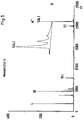
- Figure 6 shows a raw data spectrum of the thermally unstable peptide Trp-Met-Asp-Phe-NH2.
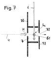
- the further exemplary embodiment of the device according to the invention shown in FIG. 7 comprises an ionization chamber 7, the front wall or plate 70 of which is provided with an inlet opening 71 through which the molecules 4 to be examined can enter in the form of a continuous beam or as a particle packet.
- An end plate 73 is provided opposite the front plate 70 and has an outlet opening 72 aligned with the inlet opening 71.
- the molecules to be examined do not flow in on the axis defined by the inlet opening 71 and outlet opening 72, but instead reach the ionization chamber 7 from all sides by diffusion.
- ionization by electron impact can initially respectively.
- an electron beam 6 is spatially focused on the center of the ionization chamber, the energy of the electrons being adjustable from a few eV up to 100 eV.
- the electron beam 6 is also switched on in pulsed operation, the pulse duration being from 10 ns to approximately 100 ⁇ s.
- the molecular ions In order to achieve a good resolution when examining the molecular ions with a time-of-flight mass spectrometer, the molecular ions must start at a point (t ⁇ 5 ns) that is as precisely defined as possible in a space that is as small as possible ( ⁇ 1 mm). In general, it is not possible to meet these conditions and to use the entire sample contained in a gas jet. However, it has been shown that the sensitivity of the arrangement can be increased if the radiation density of the electrons used for the ionization is selected such that a potential well is generated in the focus 61 of the beam.
- the end plate 73 of the ionization chamber 7 is switched to 0 V approximately 10 ns later, this switching taking place in less than 5 ns. This provides the start pulse for the ions for their flight in the time-of-flight mass spectrometer.
- the ionization chamber 7 is again placed at positive potential overall, for example at 600 V.
- the photon ionization can then be carried out.
- a pulsed laser beam 4a is irradiated into the ionization chamber 1.
- the laser pulses used have a typical duration of 5 ns.
- the short duration of the laser pulses alone would ensure a precisely defined starting time for the ions, so that the ionization chamber 7 with the closing plate 73, which can be acted upon separately, would not be required.
- the focus of the electron beam 6 and the focus of the photon beam 4a coincide in a region 61 which lies on the path of the molecules to be examined.
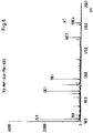
- FIG. 9 shows the raw data spectra of Pro-Phe-Gly-Lys acetate, the spectra again being recorded on the one hand by multi-photon ionization (MPI) and on the other hand by electron impact ionization (EI).
- MPI multi-photon ionization
- EI electron impact ionization
Landscapes
- Physics & Mathematics (AREA)
- Chemical & Material Sciences (AREA)
- Analytical Chemistry (AREA)
- Engineering & Computer Science (AREA)
- Plasma & Fusion (AREA)
- Optics & Photonics (AREA)
- Other Investigation Or Analysis Of Materials By Electrical Means (AREA)
- Electron Tubes For Measurement (AREA)
Priority Applications (1)
| Application Number | Priority Date | Filing Date | Title |
|---|---|---|---|
| EP95104288A EP0669638A1 (fr) | 1991-03-13 | 1992-03-07 | Procédé et dispositif pour générer des ions, en particulier pour un spectromètre de masse tel qu'un spectromètre à temps de vol, à partir de molécules thermiquement instables, non-volatiles et de masse élevée |
Applications Claiming Priority (4)
| Application Number | Priority Date | Filing Date | Title |
|---|---|---|---|
| DE4108463 | 1991-03-13 | ||
| DE4108462A DE4108462C2 (de) | 1991-03-13 | 1991-03-13 | Verfahren und Vorrichtung zum Erzeugen von Ionen aus thermisch instabilen, nichtflüchtigen großen Molekülen |
| DE4108463 | 1991-03-13 | ||
| DE4108462 | 1991-03-13 |
Related Child Applications (1)
| Application Number | Title | Priority Date | Filing Date |
|---|---|---|---|
| EP95104288.6 Division-Into | 1992-03-07 |
Publications (3)
| Publication Number | Publication Date |
|---|---|
| EP0503748A2 true EP0503748A2 (fr) | 1992-09-16 |
| EP0503748A3 EP0503748A3 (en) | 1993-04-28 |
| EP0503748B1 EP0503748B1 (fr) | 1996-12-11 |
Family
ID=25901910
Family Applications (2)
| Application Number | Title | Priority Date | Filing Date |
|---|---|---|---|
| EP92250055A Expired - Lifetime EP0503748B1 (fr) | 1991-03-13 | 1992-03-07 | Procédé pour générer des ions, en particulier pour un spectromètre de masse tel qu'un spectromètre à temps de vol, à partir de molécules thermiquement instables, non-volatiles et de masse élevée |
| EP95104288A Withdrawn EP0669638A1 (fr) | 1991-03-13 | 1992-03-07 | Procédé et dispositif pour générer des ions, en particulier pour un spectromètre de masse tel qu'un spectromètre à temps de vol, à partir de molécules thermiquement instables, non-volatiles et de masse élevée |
Family Applications After (1)
| Application Number | Title | Priority Date | Filing Date |
|---|---|---|---|
| EP95104288A Withdrawn EP0669638A1 (fr) | 1991-03-13 | 1992-03-07 | Procédé et dispositif pour générer des ions, en particulier pour un spectromètre de masse tel qu'un spectromètre à temps de vol, à partir de molécules thermiquement instables, non-volatiles et de masse élevée |
Country Status (3)
| Country | Link |
|---|---|
| US (1) | US5294797A (fr) |
| EP (2) | EP0503748B1 (fr) |
| DE (2) | DE4108462C2 (fr) |
Cited By (4)
| Publication number | Priority date | Publication date | Assignee | Title |
|---|---|---|---|---|
| EP0633602A3 (fr) * | 1993-07-02 | 1995-11-22 | Bergmann Eva Martina | Spectromètre de masse à temps de vol pourvu d'une source d'ions en phase gaseuze présentant une sensibilité élevée ainsi qu'une large gamme dynamique. |
| DE19822674A1 (de) * | 1998-05-20 | 1999-12-09 | Gsf Forschungszentrum Umwelt | Gaseinlaß für eine Ionenquelle |
| DE19822672A1 (de) * | 1998-05-20 | 1999-12-09 | Gsf Forschungszentrum Umwelt | Verfahren und Vorrichtung zur Erzeugung eines gerichteten Gasstrahls |
| DE102005005333A1 (de) * | 2005-01-28 | 2006-08-17 | Deutsches Zentrum für Luft- und Raumfahrt e.V. | Verfahren zur Aerosol-Analyse, Sondenvorrichtung und Analysevorrichtung |
Families Citing this family (31)
| Publication number | Priority date | Publication date | Assignee | Title |
|---|---|---|---|---|
| DE19608963C2 (de) * | 1995-03-28 | 2001-03-22 | Bruker Daltonik Gmbh | Verfahren zur Ionisierung schwerer Moleküle bei Atmosphärendruck |
| GB2310950A (en) * | 1996-03-08 | 1997-09-10 | Bruker Franzen Analytik Gmbh | Method for the ionization of heavy molecules at atmospheric pressure |
| DE19630547C2 (de) * | 1996-07-17 | 1998-05-28 | Forschungsverbund Berlin Ev | Verfahren zur Matrix-unterstützten Laserdesorption und Ionisierung von Analytmolekülen, insbesondere von fragilen bzw. labilen Molekülen |
| US5742050A (en) * | 1996-09-30 | 1998-04-21 | Aviv Amirav | Method and apparatus for sample introduction into a mass spectrometer for improving a sample analysis |
| DE19649201A1 (de) * | 1996-11-27 | 1998-05-28 | Max Planck Gesellschaft | Elektronenstrahlanalyse |
| DE19705762C2 (de) * | 1997-02-14 | 2001-06-07 | Rainer Edmund Weinkauf | Verfahren und Vorrichtung zum Erzeugen von Gasstrahlen |
| DE19734460A1 (de) * | 1997-08-11 | 1999-02-18 | Gsf Forschungszentrum Umwelt | Verfahren und Vorrichtung zum analytischen Nachweis von Spuren |
| US6211516B1 (en) * | 1999-02-09 | 2001-04-03 | Syagen Technology | Photoionization mass spectrometer |
| US7109476B2 (en) | 1999-02-09 | 2006-09-19 | Syagen Technology | Multiple ion sources involving atmospheric pressure photoionization |
| US6630664B1 (en) | 1999-02-09 | 2003-10-07 | Syagen Technology | Atmospheric pressure photoionizer for mass spectrometry |
| US7119342B2 (en) * | 1999-02-09 | 2006-10-10 | Syagen Technology | Interfaces for a photoionization mass spectrometer |
| DE19911801C1 (de) | 1999-03-17 | 2001-01-11 | Bruker Daltonik Gmbh | Verfahren und Vorrichtung zur matrixunterstützten Laserdesorptions-Ionisierung von Substanzen |
| DE10014847A1 (de) * | 2000-03-24 | 2001-10-04 | Gsf Forschungszentrum Umwelt | Verfahren und Vorrichtung zum Nachweis von Verbindungen in einem Gasstrom |
| DE10042394B4 (de) * | 2000-08-29 | 2006-06-29 | Dräger Safety AG & Co. KGaA | Ionenquelle für Ionenmobilitätsspektrometer mit optischer und Teilchenstrahlun gsionisation |
| US6737642B2 (en) | 2002-03-18 | 2004-05-18 | Syagen Technology | High dynamic range analog-to-digital converter |
| US20080223409A1 (en) * | 2003-12-12 | 2008-09-18 | Horsky Thomas N | Method and apparatus for extending equipment uptime in ion implantation |
| US7820981B2 (en) * | 2003-12-12 | 2010-10-26 | Semequip, Inc. | Method and apparatus for extending equipment uptime in ion implantation |
| DE102004002729B4 (de) * | 2004-01-20 | 2008-11-27 | Bruker Daltonik Gmbh | Ionisierung desorbierter Analytmoleküle bei Atmosphärendruck |
| US7291845B2 (en) * | 2005-04-26 | 2007-11-06 | Varian, Inc. | Method for controlling space charge-driven ion instabilities in electron impact ion sources |
| JP4825028B2 (ja) | 2006-03-17 | 2011-11-30 | 浜松ホトニクス株式会社 | イオン化装置 |
| JP4958258B2 (ja) * | 2006-03-17 | 2012-06-20 | 株式会社リガク | ガス分析装置 |
| EP2017875A1 (fr) * | 2007-07-16 | 2009-01-21 | Max-Planck-Gesellschaft zur Förderung der Wissenschaften e.V. | Procédé et appareil pour fournir un échantillon pour une analyse successive |
| WO2009039382A1 (fr) * | 2007-09-21 | 2009-03-26 | Semequip. Inc. | Procédé d'extension du temps de fonctionnement d'un équipement d'implantation ionique |
| US7750291B2 (en) * | 2008-02-25 | 2010-07-06 | National Sun Yat-Sen University | Mass spectrometric method and mass spectrometer for analyzing a vaporized sample |
| US8742335B2 (en) * | 2009-12-18 | 2014-06-03 | Sri International | Rotator sample introduction interface |
| CN102903597A (zh) * | 2012-10-19 | 2013-01-30 | 山东省科学院海洋仪器仪表研究所 | 一种热解吸与电子轰击相结合的离子源 |
| GB2518122B (en) * | 2013-02-19 | 2018-08-08 | Markes International Ltd | An electron ionisation apparatus |
| SG10201808165YA (en) | 2013-04-17 | 2018-10-30 | Fluidigm Canada Inc | Sample analysis for mass cytometry |
| GB201721700D0 (en) | 2017-12-22 | 2018-02-07 | Micromass Ltd | Ion source |
| JP7039439B2 (ja) * | 2018-10-26 | 2022-03-22 | 株式会社堀場製作所 | ガス分析装置及びガス分析方法 |
| CN116031138B (zh) * | 2023-01-10 | 2025-10-10 | 中国科学院大学 | 一种气相污染物全物种高灵敏在线质谱仪及检测方法 |
Family Cites Families (8)
| Publication number | Priority date | Publication date | Assignee | Title |
|---|---|---|---|---|
| FR1024654A (fr) * | 1950-09-16 | 1953-04-03 | Csf | Spectromètre de masse à sélection par temps de transit utilisant la modulation de fréquence |
| US3182190A (en) * | 1962-07-31 | 1965-05-04 | Gulf Research Development Co | Magnetic field free ion source with adjustable electron gun |
| US3296434A (en) * | 1964-05-26 | 1967-01-03 | Martin H Studier | Method of operating an ion source for a time of flight mass spectrometer |
| DE3224801C2 (de) * | 1982-07-02 | 1986-04-30 | Edward William Prof. Dr. 8000 München Schlag | Verfahren und Einrichtung zum Erzeugen von gepulsten Molekularstrahlen, die große, thermisch instabile Moleküle enthalten |
| GB2177507B (en) * | 1985-06-13 | 1989-02-15 | Mitsubishi Electric Corp | Laser mass spectroscopic analyzer |
| DE3809504C1 (fr) * | 1988-03-22 | 1989-09-21 | Bruker - Franzen Analytik Gmbh, 2800 Bremen, De | |
| DE3920566A1 (de) * | 1989-06-23 | 1991-01-10 | Bruker Franzen Analytik Gmbh | Ms-ms-flugzeit-massenspektrometer |
| GB8928917D0 (en) * | 1989-12-21 | 1990-02-28 | Vg Instr Group | Method and apparatus for surface analysis |
-
1991
- 1991-03-13 DE DE4108462A patent/DE4108462C2/de not_active Expired - Fee Related
-
1992
- 1992-03-07 EP EP92250055A patent/EP0503748B1/fr not_active Expired - Lifetime
- 1992-03-07 EP EP95104288A patent/EP0669638A1/fr not_active Withdrawn
- 1992-03-07 DE DE59207642T patent/DE59207642D1/de not_active Expired - Fee Related
- 1992-03-12 US US07/849,886 patent/US5294797A/en not_active Expired - Fee Related
Non-Patent Citations (6)
| Title |
|---|
| ANALYTICAL INSTRUMENTATION, Band 16, Nr. 1, 1987, Seiten 93-115, New York, US; J.K. OLTHOFF et al.: "Modification of Wiley-McLaren TOF analysers for laser desorption" * |
| APPLIED PHYSICS B. PHOTOPHYSICS AND CHEMISTRY, Band 51, Nr. 6, Dezember 1990, Seiten 395-403, Heidelberg, DE; G. MEIJER et al.: "Laser desorption jet-cooling of organic molecules" * |
| APPLIED PHYSICS B. PHOTOPHYSICS AND CHEMISTRY, Band B41, Nr. 6, Dezember 1990, Seiten 395-403, Heidelberg, DE; G. MEIJER et al.: "Laser desorption jet-cooling of organic molecules" * |
| PHYSICAL REVIEW, B. CONDENSED MATTER, Band 38, Nr. 5, 15. August 1988, Seiten 3517-3520, New York, US; C.W.S. CONOVER et al.: "Laser vaporisation of solids into an inert gas: a measure of high-temperature cluster stability" * |
| REVIEW OF SCIENTIFIC INSTRUMENTS, Band 58, Nr. 1, Januar 1987, Seiten 32-37, New York, US; J.E. POLLARD et al.: "Electron-impact ionization time-of-flight mass spectrometer for molecular beams" * |
| REVIEW OF SCIENTIFIC INSTRUMENTS, Band 59, Nr. 4, April 1988, Seiten 557-561, New York, US; L. LI et al.: "Pulsed laser desorption method for volatilizing thermally labile molecules for supersonic jet spectroscopy" * |
Cited By (6)
| Publication number | Priority date | Publication date | Assignee | Title |
|---|---|---|---|---|
| EP0633602A3 (fr) * | 1993-07-02 | 1995-11-22 | Bergmann Eva Martina | Spectromètre de masse à temps de vol pourvu d'une source d'ions en phase gaseuze présentant une sensibilité élevée ainsi qu'une large gamme dynamique. |
| DE19822674A1 (de) * | 1998-05-20 | 1999-12-09 | Gsf Forschungszentrum Umwelt | Gaseinlaß für eine Ionenquelle |
| DE19822672A1 (de) * | 1998-05-20 | 1999-12-09 | Gsf Forschungszentrum Umwelt | Verfahren und Vorrichtung zur Erzeugung eines gerichteten Gasstrahls |
| DE19822672B4 (de) * | 1998-05-20 | 2005-11-10 | GSF - Forschungszentrum für Umwelt und Gesundheit GmbH | Verfahren und Vorrichtung zur Erzeugung eines gerichteten Gasstrahls |
| DE102005005333A1 (de) * | 2005-01-28 | 2006-08-17 | Deutsches Zentrum für Luft- und Raumfahrt e.V. | Verfahren zur Aerosol-Analyse, Sondenvorrichtung und Analysevorrichtung |
| DE102005005333B4 (de) * | 2005-01-28 | 2008-07-31 | Deutsches Zentrum für Luft- und Raumfahrt e.V. | Verfahren zur Probennahme und Aerosol-Analyse |
Also Published As
| Publication number | Publication date |
|---|---|
| DE4108462C2 (de) | 1994-10-13 |
| EP0503748B1 (fr) | 1996-12-11 |
| EP0503748A3 (en) | 1993-04-28 |
| EP0669638A1 (fr) | 1995-08-30 |
| DE4108462A1 (de) | 1992-09-17 |
| DE59207642D1 (de) | 1997-01-23 |
| US5294797A (en) | 1994-03-15 |
Similar Documents
| Publication | Publication Date | Title |
|---|---|---|
| EP0503748B1 (fr) | Procédé pour générer des ions, en particulier pour un spectromètre de masse tel qu'un spectromètre à temps de vol, à partir de molécules thermiquement instables, non-volatiles et de masse élevée | |
| DE69132461T2 (de) | Verfahren und vorrichtung zur spurenanalyse | |
| DE69631556T2 (de) | Biomolekülenanalyse mittels Flugzeitmassenspektrometrie | |
| DE4202123C2 (de) | Vorrichtung für die massenspektrometrische Untersuchung schneller organischer Ionen | |
| DE19511333C1 (de) | Verfahren und Vorrichtung für orthogonalen Einschuß von Ionen in ein Flugzeit-Massenspektrometer | |
| EP1200984B1 (fr) | Procede et dispositif de fragmentation d'agglomerats | |
| DE19822672B4 (de) | Verfahren und Vorrichtung zur Erzeugung eines gerichteten Gasstrahls | |
| DE4441972C2 (de) | Verfahren und Vorrichtung zum Nachweis von Probenmolekülen in einem Trägergas | |
| DE102021105327B3 (de) | Desorptions-Ionenquelle mit Postdesorptions-Ionisierung in Transmissionsgeometrie | |
| DE69031062T2 (de) | Verfahren und Vorrichtung zur massenspektrometrischen Analyse | |
| EP0112858B1 (fr) | Procede et dispositif pour la production de faisceaux moleculaires et mise en oeuvre de ce procede | |
| DE1922871B2 (de) | Ionenquelle | |
| WO2005117062A2 (fr) | Procede et dispositif d'analyse par spectrometrie de masse d'analytes | |
| DE19637480C2 (de) | Vorrichtung zur massenspektrometrischen Analyse von Oberflächen | |
| EP1915770B1 (fr) | Procede et dispositif pour la detection de composes par spectrometrie de masse | |
| DE2048862A1 (de) | Vorrichtung zur spektralphotometri sehen Analyse | |
| DE4317749A1 (de) | Massenspektrometer mit Einrichtungen zum Überwachen der Strahlung, die ausgesendet wird, wenn Ionen mit einem Zielgas kollidieren | |
| DE19547949C2 (de) | Flugzeitmassenspektrometer | |
| DE102017218456B3 (de) | Vorrichtung und Verfahren zum Erzeugen von Ionenpulsen sowie deren Verwendung | |
| DE102018106412B4 (de) | Teilchenspektrometer und Teilchenspektrometrieverfahren | |
| DE102016112328B3 (de) | Ionenmikroskopievorrichtung | |
| DE19756444C1 (de) | Verfahren und Vorrichtung zum Nachweis von Probenmolekülen in einem Trägergas | |
| DE19705762C2 (de) | Verfahren und Vorrichtung zum Erzeugen von Gasstrahlen | |
| DE19630547C2 (de) | Verfahren zur Matrix-unterstützten Laserdesorption und Ionisierung von Analytmolekülen, insbesondere von fragilen bzw. labilen Molekülen | |
| DE10015415C2 (de) | Verfahren und Vorrichtung zur Erzeugung hochenergetischer Ionenstrahlen und/oder kurzwelliger elektromagnetischer Strahlung |
Legal Events
| Date | Code | Title | Description |
|---|---|---|---|
| PUAI | Public reference made under article 153(3) epc to a published international application that has entered the european phase |
Free format text: ORIGINAL CODE: 0009012 |
|
| AK | Designated contracting states |
Kind code of ref document: A2 Designated state(s): DE FR GB |
|
| PUAL | Search report despatched |
Free format text: ORIGINAL CODE: 0009013 |
|
| AK | Designated contracting states |
Kind code of ref document: A3 Designated state(s): DE FR GB |
|
| 17P | Request for examination filed |
Effective date: 19930524 |
|
| 17Q | First examination report despatched |
Effective date: 19941123 |
|
| GRAG | Despatch of communication of intention to grant |
Free format text: ORIGINAL CODE: EPIDOS AGRA |
|
| RTI1 | Title (correction) | ||
| GRAH | Despatch of communication of intention to grant a patent |
Free format text: ORIGINAL CODE: EPIDOS IGRA |
|
| GRAH | Despatch of communication of intention to grant a patent |
Free format text: ORIGINAL CODE: EPIDOS IGRA |
|
| GRAA | (expected) grant |
Free format text: ORIGINAL CODE: 0009210 |
|
| AK | Designated contracting states |
Kind code of ref document: B1 Designated state(s): DE FR GB |
|
| DX | Miscellaneous (deleted) | ||
| ET | Fr: translation filed | ||
| GBT | Gb: translation of ep patent filed (gb section 77(6)(a)/1977) |
Effective date: 19961211 |
|
| REF | Corresponds to: |
Ref document number: 59207642 Country of ref document: DE Date of ref document: 19970123 |
|
| PLBE | No opposition filed within time limit |
Free format text: ORIGINAL CODE: 0009261 |
|
| 26N | No opposition filed | ||
| REG | Reference to a national code |
Ref country code: GB Ref legal event code: IF02 |
|
| PGFP | Annual fee paid to national office [announced via postgrant information from national office to epo] |
Ref country code: GB Payment date: 20020306 Year of fee payment: 11 |
|
| PGFP | Annual fee paid to national office [announced via postgrant information from national office to epo] |
Ref country code: FR Payment date: 20020312 Year of fee payment: 11 |
|
| PGFP | Annual fee paid to national office [announced via postgrant information from national office to epo] |
Ref country code: DE Payment date: 20020318 Year of fee payment: 11 |
|
| PG25 | Lapsed in a contracting state [announced via postgrant information from national office to epo] |
Ref country code: GB Free format text: LAPSE BECAUSE OF NON-PAYMENT OF DUE FEES Effective date: 20030307 |
|
| PG25 | Lapsed in a contracting state [announced via postgrant information from national office to epo] |
Ref country code: DE Free format text: LAPSE BECAUSE OF NON-PAYMENT OF DUE FEES Effective date: 20031001 |
|
| GBPC | Gb: european patent ceased through non-payment of renewal fee |
Effective date: 20030307 |
|
| PG25 | Lapsed in a contracting state [announced via postgrant information from national office to epo] |
Ref country code: FR Free format text: LAPSE BECAUSE OF NON-PAYMENT OF DUE FEES Effective date: 20031127 |
|
| REG | Reference to a national code |
Ref country code: FR Ref legal event code: ST |