EP0503920A2 - Appareil et système pour fournir un support de diagnostic pour un ou plusieurs systèmes à calculatrice - Google Patents
Appareil et système pour fournir un support de diagnostic pour un ou plusieurs systèmes à calculatrice Download PDFInfo
- Publication number
- EP0503920A2 EP0503920A2 EP92302073A EP92302073A EP0503920A2 EP 0503920 A2 EP0503920 A2 EP 0503920A2 EP 92302073 A EP92302073 A EP 92302073A EP 92302073 A EP92302073 A EP 92302073A EP 0503920 A2 EP0503920 A2 EP 0503920A2
- Authority
- EP
- European Patent Office
- Prior art keywords
- local
- local computer
- diagnostic
- computer system
- host
- Prior art date
- Legal status (The legal status is an assumption and is not a legal conclusion. Google has not performed a legal analysis and makes no representation as to the accuracy of the status listed.)
- Withdrawn
Links
Images
Classifications
-
- G—PHYSICS
- G06—COMPUTING OR CALCULATING; COUNTING
- G06F—ELECTRIC DIGITAL DATA PROCESSING
- G06F11/00—Error detection; Error correction; Monitoring
- G06F11/22—Detection or location of defective computer hardware by testing during standby operation or during idle time, e.g. start-up testing
- G06F11/2294—Detection or location of defective computer hardware by testing during standby operation or during idle time, e.g. start-up testing by remote test
-
- G—PHYSICS
- G06—COMPUTING OR CALCULATING; COUNTING
- G06F—ELECTRIC DIGITAL DATA PROCESSING
- G06F11/00—Error detection; Error correction; Monitoring
- G06F11/07—Responding to the occurrence of a fault, e.g. fault tolerance
- G06F11/0703—Error or fault processing not based on redundancy, i.e. by taking additional measures to deal with the error or fault not making use of redundancy in operation, in hardware, or in data representation
- G06F11/0706—Error or fault processing not based on redundancy, i.e. by taking additional measures to deal with the error or fault not making use of redundancy in operation, in hardware, or in data representation the processing taking place on a specific hardware platform or in a specific software environment
- G06F11/0748—Error or fault processing not based on redundancy, i.e. by taking additional measures to deal with the error or fault not making use of redundancy in operation, in hardware, or in data representation the processing taking place on a specific hardware platform or in a specific software environment in a remote unit communicating with a single-box computer node experiencing an error/fault
Definitions
- the present invention relates to an apparatus for enabling diagnostic support to be given to one or more computer systems from a remote host systems and a system for providing diagnostic support to one or more computer systems.
- Diagnostic support in this context means any way of discovering the cause of the computer system problem. It includes manually looking at computer system error reports, automatically looking at system error reports using commercial software and running special diagnostic programs.
- the engineer may require the services of a specialist or obtain spare parts to replace faulty parts in order to get the computer system operational again.
- the problem could be solved by the operator at the computer system but in order to diagnose the problem, usually it is necessary for the engineer to attend the installed computer system.
- An aim of the present invention is to create an apparatus for enabling diagnostic support to be given to one or more local computer systems from a remote host computer system. This enables a problem associated with one of the local computer systems to be identified and the host system diagnose the problem and propose suitable solutions more quickly than done before.
- Another aim of the present invention is to provide a system for providing diagnostic support to one or more local computer systems from a remote host computer thereby obviating the above disadvantages.
- an apparatus for enabling diagnostic support to be given to one or more local computer systems from a remote host computer system comprising: means for passing data between each of said local computer systems and a respective local console even when there is no power to the apparatus; means for controlling diagnostic data being passed between said local computer system and the respective local console and between each said local computer system and said host system; whereby diagnostic data from any one of said local computer system can be passed to the host system and local console for processing and diagnostic support can be passed back from the host computer to the problematic local computer system and logged on the respective local console.
- This apparatus enables a problem of one of the local computer systems to be identified and diagnostic data to be passed to the host system for diagnosis and proposal of a solution. Consequently, the time spent on any computer system being down can be dramatically minimised over known support arrangements.
- a system for providing diagnostic support to one or more local computer systems comprising: a remote host system being provided with diagnostic software; one or more local consoles also being provided with diagnostic software; and a central console for coupling each local console to the respective local computer system, said central console being coupled to said host system; whereby diagnostic data from any one of said local computer systems can be passed to the host system and local console for processing and diagnostic support from said host computer can be passed back to the local computer system and logged for analysis on the respective local console.
- diagnosis of the problem can begin even before an engineer is sent out to the installed computer system. If necessary, the need for a specialist can be identified more quickly and sent out to the installed computer system more quickly. Similarly, if new parts are necessary, these can be ordered and even sent with an engineer to the installed computer system.
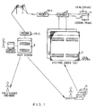
- the system of the preferred embodiment enables diagnostic support to be provided to one or more local computer systems (2).
- Each local computer system (2) is coupled to a respective local console (4) via an apparatus (6) known as a remote support processor.
- the remote support processor (6), local consoles (4) and local computer systems (2) are all installed on site at a particular client's location.
- the remote support processor (6) in the preferred embodiment can support up to eight local computer systems at any one time. However, only one diagnostic session concerning one local computer system can take place at any one time.
- the system enables diagnostic data about any one of the local computer system (2) to be sent to a host system (8) through one or more modems (10).
- the host system (8) is installed at a remote location to that of the remote support processor (6), local consoles (4) and local computer systems (2).
- the remote support processor is provided as a buffer between the host system (8) and the local computer systems (2) which is a necessity when the systems (2), (8) have different baud rates.
- the diagnostic data may be sent by telephone, satellite, cable transmission or any other telecommunication method.
- the diagnostic data is sent via a first modem (10.1) on a telephone link and then to the host computer via a second modem (10.2).
- Both the host computer and each local console (4) have diagnostic software and command files for identifying and diagnosing a problem on a local computer system (2).
- diagnostic data can be collated and passed to the host system and the respective local console for diagnoses and the proposal of suitable solutions.
- the local console logs all data being sent to and from the respective local computer system for security reasons and enables on site diagnosis and implementation of solutions.
- diagnostic data from the local computer systems is sent in a diagnostic session to the host computer system and such is analysed thereby, all in real time.
- the connection between the host system and the remote support processor is lost, then all output from the local system is recorded in the memory of the remote support processor.
- the connection can be re-made and all output from the local system which occured can be recovered by the host computer. Consequently, the host system (8) has the capabilitiesilty of down-loading and up-loading diagnostic data and recording the diagnostic session for any particular local computer system for later off-line evaluation.
- the solution to the problem is found by the host computer and passed back to the respective local computer system without an engineer even attending the site. If the solution is not that simple, an engineer or specialist engineer can be found and sent to the site of the local computer system without delay. The engineer can then use the local console in association with the host computer to find and implement a solution. Furthermore, if required, spare parts (12) can be ordered and sent to the installed local computer system without any further delay.
- the remote support processor (6) has at least four modes or operation. These are as follows:
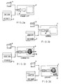
- the remote support processor (6) is a single unit which may be a free-standing unit or rack mounted.
- each remote support processor (6) comprises a front panel (22), the CPU (18), a distribution panel (24) and two input-output (I/O) connector cards (26).
- the I/O connections comprise RS232L ports.
- the remote support processor is also provided with a power supply (27).
- the distribution panel (24) contains all the 25 way 'D' type connectors for coupling the remote support processor (6) up to a maximum of eight local consoles (4), eight local computer systems (2) and the modem (10.1).
- the distribution panel (24) is also connected to the two identical I/O connections (26).
- Each I/O connection as shown in figure (4), comprises the relay (14) and electronic switch (16).
- the electronic switches comprise custom programmed PAL devices.
- the CPU (18) controls the flow of data through the I/O connections (26).
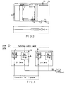
- the operation of the remote support processor is also dictated by the settings on the front panel (22).
- the front panel (22) includes eight port disable switches (28), a display (30), a test switch (34) and a reset switch (32); and is coupled to a key switch (36) which has three position, test, enable or disable.
- the eight port disable switches (28) enable an operator to select which one of the eight local computer systems are coupled to the remote support processor (6).
- the particular number of the chosen local computer system is then displayed on the display (30).
- Other information such as status messages may be displayed on the display as follows:
- the remote support processor is re-initialising one of the modems which has defaulted to factory setups.
- the keyswitch (36) is in the disabled position and so modem (10.1) will not automatically answer and non of the local computer systems can be accessed.
- the keyswitch (36) is in the test or enabled position and is waiting for the host computer to connect. This symbol is shown whenever no telephone line connection is made.
- This host computer is connected to a system but no diagnostic session is in progress (e.g. port 7).
- the local computer system and local console are under control of the remote support processor and the local console should only be used under the direction of the host computer.
- Disable - all remote access from the host computer to the remote support processor is prevented, and the modem will not answer an incoming call. If the switch is turned to this position during a diagnostic session the session will be terminated. This is the only recommended way of aborting an unauthorised session.
- Test - the test switch enables the host computer to access the remote support processor but stops any access to the local computer systems even if the port switches are enabled. This can thus be used to periodically test the remote support processor remotely. Furthermore, this position on the keyswitch allows connection to the remote support processor by the host computer to perform such functions as setting the time and date, but it will not allow the host to connect to any of the local systems, even though the port switches may be enabled.
- the reset switch will restart the remote support processor, any diagnostic session in progress will be abnormally terminated. If pressed it may leave the system under test in an indeterminte state.
- the keyswitch in the disable position should be used to abort an unauthorised session.
- test switch if pressed will allow the remote support processor to perform a more extensive self test. All the functions of the remote support processor will be as normal EXCEPT NO PASSWORD CHECKING WILL OCCUR. This mode is designed to enable a user to access his own systems if required.
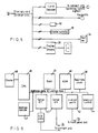
- the CPU comprises a microprocessor (37) supported by a real time clock (38), four asynchronous communication lines (40) which are coupled to the I/O connections (16), an I/O port (42) for receiving information from the front panel (22), an interrupt means (44), memory (20) another memory (46), and an address decoder means (47).
- the memory (20) comprises two random access memory chips of 32Kb
- memory (46) is provided by two 64Kb EPROMS
- address decoder means (47) comprises a PAL16L8 field programmable logic array.
- the microprocessor (37) is driven by a clock (48).
- the clock comprises an 8284 clock driver chip and a 22.1184 Mhz crystal. This clock driver also provides the reset line to the microprocessor (37) and other peripheral chips of the CPU (18).
- No wait states are used in the CPU (18) so that the ready lines of the clock driver chip are tied high. All the components coupled to the microprocessor (37) are fast enough to conform to the minimum set up and hold time require in the system.
- the power on the reset line of the clock driver chip is held low on power up until the power supply (27) has stablised. Stablising the power supply is achieved, as is usual, by an RC combination (not shown).
- a battery back up switch i.c. output (not shown) is coupled to the reset line so as to hold the reset line low until the power supply (27) exceeds the voltage of the back up battery.
- the CPU (18) of the remote support console (6) is used to control data being passed between the local computer system and its respective local console and between the local computer system and the host computer.
- the microprocessor (37) of the CPU (18) maintains several ring buffers in the RAM (20).
- a second embodiment of the present invention comprises a remote support processor for enabling diagnostic support to be given to only one local computer system.
- This remote support processor is a modification of the above described remote support processor and has several capabilities over and above it.
- the remote support processor of the second embodiment is permanently connected to the local system and so can be dedicated to monitor that single system and the following advantages can be realised .
- the remote support processor can detect user defined error messages and notify a local console and also call or dial several pre-defined remote locations (i.e. Pager service, software support, or engineers).
- the local or remote operator can review the last 32000 characters sent from the local system stored in the remote support processor.
Landscapes
- Engineering & Computer Science (AREA)
- General Engineering & Computer Science (AREA)
- Theoretical Computer Science (AREA)
- Computer Hardware Design (AREA)
- Quality & Reliability (AREA)
- Physics & Mathematics (AREA)
- General Physics & Mathematics (AREA)
- Test And Diagnosis Of Digital Computers (AREA)
- Debugging And Monitoring (AREA)
Applications Claiming Priority (2)
| Application Number | Priority Date | Filing Date | Title |
|---|---|---|---|
| GB9105099 | 1991-03-11 | ||
| GB919105099A GB9105099D0 (en) | 1991-03-11 | 1991-03-11 | Apparatus and system for providing diagnostic support to one or more computer systems |
Publications (2)
| Publication Number | Publication Date |
|---|---|
| EP0503920A2 true EP0503920A2 (fr) | 1992-09-16 |
| EP0503920A3 EP0503920A3 (en) | 1993-04-21 |
Family
ID=10691344
Family Applications (1)
| Application Number | Title | Priority Date | Filing Date |
|---|---|---|---|
| EP19920302073 Withdrawn EP0503920A3 (en) | 1991-03-11 | 1992-03-11 | Apparatus and system for providing diagnostic support to one or more computer systems |
Country Status (2)
| Country | Link |
|---|---|
| EP (1) | EP0503920A3 (fr) |
| GB (1) | GB9105099D0 (fr) |
Cited By (5)
| Publication number | Priority date | Publication date | Assignee | Title |
|---|---|---|---|---|
| WO1994008289A1 (fr) * | 1992-10-02 | 1994-04-14 | Compaq Computer Corporation | Systeme d'alerte et de reprise apres incident dans un ordinateur |
| EP0778529A1 (fr) * | 1995-12-05 | 1997-06-11 | Samsung Electronics Co., Ltd. | Système d'exécution des services à distance diagnostiques et de restoration |
| EP0917061A1 (fr) * | 1997-11-11 | 1999-05-19 | Corita Consultancy Limited | Procédé et système de support de traitement de données |
| DE19837214A1 (de) * | 1998-08-17 | 2000-02-24 | Siemens Ag | Verfahren und Vorrichtung zum Erfassen und Bereitstellen von Fehlerindikatoren |
| GB2355821A (en) * | 1999-10-29 | 2001-05-02 | Futuremark Oy | Computer upgrading and technical support |
Family Cites Families (3)
| Publication number | Priority date | Publication date | Assignee | Title |
|---|---|---|---|---|
| US4442502A (en) * | 1981-03-30 | 1984-04-10 | Datapoint Corporation | Digital information switching system |
| FR2575847A1 (fr) * | 1985-01-04 | 1986-07-11 | Pragmadyne Sarl | Dispositif et procede d'assistance d'une unite de traitement informatique |
| EP0315653B1 (fr) * | 1986-12-18 | 1992-07-22 | Digital Equipment Corporation | Console de teleservices pour systeme de traitement de donnees numeriques |
-
1991
- 1991-03-11 GB GB919105099A patent/GB9105099D0/en active Pending
-
1992
- 1992-03-11 EP EP19920302073 patent/EP0503920A3/en not_active Withdrawn
Cited By (10)
| Publication number | Priority date | Publication date | Assignee | Title |
|---|---|---|---|---|
| WO1994008289A1 (fr) * | 1992-10-02 | 1994-04-14 | Compaq Computer Corporation | Systeme d'alerte et de reprise apres incident dans un ordinateur |
| US5390324A (en) * | 1992-10-02 | 1995-02-14 | Compaq Computer Corporation | Computer failure recovery and alert system |
| US5596711A (en) * | 1992-10-02 | 1997-01-21 | Compaq Computer Corporation | Computer failure recovery and alert system |
| US5956475A (en) * | 1992-10-02 | 1999-09-21 | Compaq Computer Corporation | Computer failure recovery and alert system |
| US6101617A (en) * | 1992-10-02 | 2000-08-08 | Compaq Computer Corporation | Computer failure recovery and alert system |
| EP0778529A1 (fr) * | 1995-12-05 | 1997-06-11 | Samsung Electronics Co., Ltd. | Système d'exécution des services à distance diagnostiques et de restoration |
| EP0917061A1 (fr) * | 1997-11-11 | 1999-05-19 | Corita Consultancy Limited | Procédé et système de support de traitement de données |
| DE19837214A1 (de) * | 1998-08-17 | 2000-02-24 | Siemens Ag | Verfahren und Vorrichtung zum Erfassen und Bereitstellen von Fehlerindikatoren |
| DE19837214C2 (de) * | 1998-08-17 | 2002-03-28 | Siemens Ag | Verfahren und Vorrichtung zum Erfassen und Bereitstellen von Fehlerindikatoren |
| GB2355821A (en) * | 1999-10-29 | 2001-05-02 | Futuremark Oy | Computer upgrading and technical support |
Also Published As
| Publication number | Publication date |
|---|---|
| GB9105099D0 (en) | 1991-04-24 |
| EP0503920A3 (en) | 1993-04-21 |
Similar Documents
| Publication | Publication Date | Title |
|---|---|---|
| US4665501A (en) | Workstation for local and remote data processing | |
| US4953165A (en) | Diagnostic system for personal computer | |
| EP0068108A2 (fr) | Système et procédé pour le diagnostique et la correction d'erreurs dans un équipement de traitement de données éloigné | |
| US4719626A (en) | Diagnostic method and apparatus for channel control apparatus | |
| US5202963A (en) | Method and apparatus for adapting a remote communications controller to a variety of types of communications modems | |
| EP0515760B1 (fr) | ContrÔleur de communication comprenant des adaptateurs de ligne chargeables d'un programme d'application | |
| US5034596A (en) | IC card processing apparatus | |
| US4703446A (en) | Data processing unit diagnosis control apparatus | |
| EP0503920A2 (fr) | Appareil et système pour fournir un support de diagnostic pour un ou plusieurs systèmes à calculatrice | |
| EP0198170B1 (fr) | Circuit moniteur | |
| HK21395A (en) | Diagnostic system for digitally controlled devices | |
| US5448720A (en) | Information processing system for obtaining status data of a simplex system by a standby system of a duplex system | |
| JP2519276B2 (ja) | 障害情報収集処理方式 | |
| JPH10303900A (ja) | 電子回路キャビネット監視装置 | |
| EP0378398B1 (fr) | Système de traitement de données avec moyens pour la détection de l'état du dispositif de traitement de données recevant des commandes | |
| JP2738173B2 (ja) | スタンドアロン型装置の診断システム | |
| JP2752911B2 (ja) | ポート接続確認方法 | |
| JP3068524B2 (ja) | リモートデバッグシステム | |
| JP2710777B2 (ja) | 中間制御装置のテスト回路 | |
| JPH07302208A (ja) | 保護継電装置 | |
| CA1316608C (fr) | Dispositif de correction des erreurs pour systeme de traitement de donnees a auto-protection | |
| JPH1011370A (ja) | 多重化システム | |
| JP3094932B2 (ja) | 装置間データ試験方式 | |
| JPH0662114A (ja) | プロセッサ間診断処理方式 | |
| JPS5918722B2 (ja) | プロセス制御装置 |
Legal Events
| Date | Code | Title | Description |
|---|---|---|---|
| PUAI | Public reference made under article 153(3) epc to a published international application that has entered the european phase |
Free format text: ORIGINAL CODE: 0009012 |
|
| AK | Designated contracting states |
Kind code of ref document: A2 Designated state(s): DE FR GB |
|
| 17P | Request for examination filed |
Effective date: 19921028 |
|
| PUAL | Search report despatched |
Free format text: ORIGINAL CODE: 0009013 |
|
| AK | Designated contracting states |
Kind code of ref document: A3 Designated state(s): DE FR GB |
|
| 18D | Application deemed to be withdrawn |
Effective date: 19941005 |