EP0504095A2 - Réparation de composant de moteur de turbine à gaz - Google Patents
Réparation de composant de moteur de turbine à gaz Download PDFInfo
- Publication number
- EP0504095A2 EP0504095A2 EP92630028A EP92630028A EP0504095A2 EP 0504095 A2 EP0504095 A2 EP 0504095A2 EP 92630028 A EP92630028 A EP 92630028A EP 92630028 A EP92630028 A EP 92630028A EP 0504095 A2 EP0504095 A2 EP 0504095A2
- Authority
- EP
- European Patent Office
- Prior art keywords
- component
- recited
- layer
- laser beam
- recast layer
- Prior art date
- Legal status (The legal status is an assumption and is not a legal conclusion. Google has not performed a legal analysis and makes no representation as to the accuracy of the status listed.)
- Withdrawn
Links
Images

Classifications
-
- F—MECHANICAL ENGINEERING; LIGHTING; HEATING; WEAPONS; BLASTING
- F02—COMBUSTION ENGINES; HOT-GAS OR COMBUSTION-PRODUCT ENGINE PLANTS
- F02C—GAS-TURBINE PLANTS; AIR INTAKES FOR JET-PROPULSION PLANTS; CONTROLLING FUEL SUPPLY IN AIR-BREATHING JET-PROPULSION PLANTS
- F02C7/00—Features, components parts, details or accessories, not provided for in, or of interest apart form groups F02C1/00 - F02C6/00; Air intakes for jet-propulsion plants
-
- F—MECHANICAL ENGINEERING; LIGHTING; HEATING; WEAPONS; BLASTING
- F01—MACHINES OR ENGINES IN GENERAL; ENGINE PLANTS IN GENERAL; STEAM ENGINES
- F01D—NON-POSITIVE DISPLACEMENT MACHINES OR ENGINES, e.g. STEAM TURBINES
- F01D5/00—Blades; Blade-carrying members; Heating, heat-insulating, cooling or antivibration means on the blades or the members
- F01D5/005—Repairing methods or devices
-
- B—PERFORMING OPERATIONS; TRANSPORTING
- B23—MACHINE TOOLS; METAL-WORKING NOT OTHERWISE PROVIDED FOR
- B23K—SOLDERING OR UNSOLDERING; WELDING; CLADDING OR PLATING BY SOLDERING OR WELDING; CUTTING BY APPLYING HEAT LOCALLY, e.g. FLAME CUTTING; WORKING BY LASER BEAM
- B23K26/00—Working by laser beam, e.g. welding, cutting or boring
- B23K26/352—Working by laser beam, e.g. welding, cutting or boring for surface treatment
- B23K26/354—Working by laser beam, e.g. welding, cutting or boring for surface treatment by melting
-
- C—CHEMISTRY; METALLURGY
- C21—METALLURGY OF IRON
- C21D—MODIFYING THE PHYSICAL STRUCTURE OF FERROUS METALS; GENERAL DEVICES FOR HEAT TREATMENT OF FERROUS OR NON-FERROUS METALS OR ALLOYS; MAKING METAL MALLEABLE, e.g. BY DECARBURISATION OR TEMPERING
- C21D1/00—General methods or devices for heat treatment, e.g. annealing, hardening, quenching or tempering
-
- B—PERFORMING OPERATIONS; TRANSPORTING
- B23—MACHINE TOOLS; METAL-WORKING NOT OTHERWISE PROVIDED FOR
- B23K—SOLDERING OR UNSOLDERING; WELDING; CLADDING OR PLATING BY SOLDERING OR WELDING; CUTTING BY APPLYING HEAT LOCALLY, e.g. FLAME CUTTING; WORKING BY LASER BEAM
- B23K2101/00—Articles made by soldering, welding or cutting
- B23K2101/005—Camshafts
-
- Y—GENERAL TAGGING OF NEW TECHNOLOGICAL DEVELOPMENTS; GENERAL TAGGING OF CROSS-SECTIONAL TECHNOLOGIES SPANNING OVER SEVERAL SECTIONS OF THE IPC; TECHNICAL SUBJECTS COVERED BY FORMER USPC CROSS-REFERENCE ART COLLECTIONS [XRACs] AND DIGESTS
- Y10—TECHNICAL SUBJECTS COVERED BY FORMER USPC
- Y10T—TECHNICAL SUBJECTS COVERED BY FORMER US CLASSIFICATION
- Y10T29/00—Metal working
- Y10T29/49—Method of mechanical manufacture
- Y10T29/49316—Impeller making
- Y10T29/49318—Repairing or disassembling
-
- Y—GENERAL TAGGING OF NEW TECHNOLOGICAL DEVELOPMENTS; GENERAL TAGGING OF CROSS-SECTIONAL TECHNOLOGIES SPANNING OVER SEVERAL SECTIONS OF THE IPC; TECHNICAL SUBJECTS COVERED BY FORMER USPC CROSS-REFERENCE ART COLLECTIONS [XRACs] AND DIGESTS
- Y10—TECHNICAL SUBJECTS COVERED BY FORMER USPC
- Y10T—TECHNICAL SUBJECTS COVERED BY FORMER US CLASSIFICATION
- Y10T29/00—Metal working
- Y10T29/49—Method of mechanical manufacture
- Y10T29/49316—Impeller making
- Y10T29/49336—Blade making
-
- Y—GENERAL TAGGING OF NEW TECHNOLOGICAL DEVELOPMENTS; GENERAL TAGGING OF CROSS-SECTIONAL TECHNOLOGIES SPANNING OVER SEVERAL SECTIONS OF THE IPC; TECHNICAL SUBJECTS COVERED BY FORMER USPC CROSS-REFERENCE ART COLLECTIONS [XRACs] AND DIGESTS
- Y10—TECHNICAL SUBJECTS COVERED BY FORMER USPC
- Y10T—TECHNICAL SUBJECTS COVERED BY FORMER US CLASSIFICATION
- Y10T29/00—Metal working
- Y10T29/49—Method of mechanical manufacture
- Y10T29/49718—Repairing
- Y10T29/49721—Repairing with disassembling
- Y10T29/49723—Repairing with disassembling including reconditioning of part
- Y10T29/49725—Repairing with disassembling including reconditioning of part by shaping
- Y10T29/49726—Removing material
- Y10T29/49728—Removing material and by a metallurgical operation, e.g., welding, diffusion bonding, casting
-
- Y—GENERAL TAGGING OF NEW TECHNOLOGICAL DEVELOPMENTS; GENERAL TAGGING OF CROSS-SECTIONAL TECHNOLOGIES SPANNING OVER SEVERAL SECTIONS OF THE IPC; TECHNICAL SUBJECTS COVERED BY FORMER USPC CROSS-REFERENCE ART COLLECTIONS [XRACs] AND DIGESTS
- Y10—TECHNICAL SUBJECTS COVERED BY FORMER USPC
- Y10T—TECHNICAL SUBJECTS COVERED BY FORMER US CLASSIFICATION
- Y10T29/00—Metal working
- Y10T29/49—Method of mechanical manufacture
- Y10T29/49718—Repairing
- Y10T29/49746—Repairing by applying fluent material, e.g., coating, casting
Definitions
- This invention relates to gas turbine engine components and more particularly to a method of repairing worn and damaged components by adding material and reconfiguring the airfoil contours. This invention also relates to laser processing of materials.
- a gas turbine engine includes a compressor section, a combustion section and a turbine section. Disposed within the turbine section are alternating rings of moving blades and stationary vanes. The rings, or stages, of vanes and blades are situated such that the axes of the rings are co-located with the axis of the gas turbine engine. The blades are mounted on a disk which rotates about its central axis. As hot combustion gases exit the combustor and pass through the turbine section, the disks with blades mounted thereon are rotatably driven, turning a shaft, and thereby providing shaft work for driving the compressor section and other auxiliary systems. Higher gas temperatures mean that more work can be extracted from the gases in the turbine section, thus increasing the overall efficiency of the gas turbine engine. By using cobalt and nickel-base superalloy materials, which maintain mechanical strength at high temperatures, the operating temperature capability of the turbine section is increased.
- the stationary vanes disposed between the rings of moving blades stabilize and direct the gas flow from one stage of moving turbine blades to the next stage.
- the stabilization of the gas flow optimizes the amount of work extracted from the hot gases in the turbine section.
- the most efficient operation occurs when the nozzle flow areas, defined as the spaces between adjacent vanes in a vane ring, are all approximately equal.
- the vanes are classified in groups according to ranges of flow area.
- the acceptable flow areas for one stage of stationary vanes range from 1.868-1.894 square inches.
- vanes In service, deterioration of the vane surface occurs due to oxidation, cracking and metal erosion caused by abrasives and corrosives in the flowing gas stream.
- the high gas pressures at high temperature cause distortion of the vanes, thereby enlarging the nozzle area with a consequent loss in turbine efficiency.
- the vanes are inspected for physical damage and measured to determine the degree of flow area change and the effect on nozzle flow area classification. Before these vanes can be returned to the engine, any physical damage must be repaired and the vanes otherwise reclassified.
- Repair methods include, for example, conventional fusion welding, plasma spray as described in, for example, United States Patent No. 4,878,953, and the use of a tape material containing a mixture of a binder and a metal alloy powder which is compatible with the substrate alloy.
- the metal alloy mixture is formed into a flexible tape of uniform thickness and backed with an adhesive. After the tape is added to the vane, the vane is heated to a temperature at which the adhesive and binder decompose and at which diffusion occurs between the alloy powder and the substrate alloy. This latter technique is described in United States Patent No. 4,726,101 issued to Draghi et al., which is incorporated herein by reference.
- Methods for reclassifying the vanes to change the area between adjacent vanes include, for example, hot striking or otherwise bending the trailing edge of the vane, and adding material to the airfoil surface to change its contour, using, for example, the techniques listed above for vane repair.
- Hot striking in addition to requiring a very expensive set of contour dies and end locators for each vane configuration, can cause cracking in the airfoil or distortion of the vane platform.
- the contour dies and locators experience wear and distortion during use, and require frequent refurbishment. Hot striking does not provide a consistent amount of reconfiguration due to dimensional variations in the vanes. Additionally, hot striking is not permitted on several high temperature alloys used in gas turbine engines due to the deleterious effects on material properties such as fatigue strength.
- This and other objects of the present invention are achieved by repairing defects and replacing eroded material, and reclassifying by directing a laser beam toward the surface of the vane to be relocated.
- the function of the laser beam is to locally melt a thin layer of the vane surface, which is then allowed to solidify. Contraction of this solidified layer during cooling generates tensile forces on the underlying substrate, causing the substrate material to form a concave configuration, or cup, in a direction toward the source of the laser beam.
- a wide range of movement may be imparted to the vane, thus permitting significant changes in airfoil contour. These changes in contour are hereinafter referred to as reconfiguration.
- the laser beam is applied directly to the surface of the vane.
- a preferred method is to use a metallic powder tape material as described in United States Patent No. 4,726,101.
- the laser beam is applied to the surface of the metallic layer deposited during the repair/build-un operation.
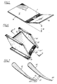
- Figure 1 is a perspective view of a laser beam striking the surface of a test sample.
- Figure 2 is a cross-section through an area on the surface of a test specimen which has been struck by a laser beam.
- Figure 3 is a perspective view of the specimen of Figure 1 showing the deformation due to the laser beam.
- Figure 4 is a perspective view of a specimen as in Figure 3 which has been constrained along the edges of the specimen.
- Figure 5 is a perspective view of a test specimen where a band across the width of the specimen has been struck by a laser beam.
- Figure 6 is a perspective view of a gas turbine engine turbine vane.
- Figure 7 is a cross-section at 7-7 of the turbine vane of Figure 6.
- the essential aspect of the invention is that the brief localized application of the laser beam to the surface of a thin metallic article can cause a change in the overall shape of the article.
- the change in shape of the article can be controlled.
- the invention may be understood through reference to Figure 1, which shows a pulsed laser beam 2 striking the surface of a metal test specimen 4 at a point 6 after passing through a focusing lens 8.
- Figure 2 shows a pulsed laser beam 2 striking the surface of a metal test specimen 4 at a point 6 after passing through a focusing lens 8.
- the laser beam melts a thin layer 10 of the test specimen 4.
- the thin pool of molten metal solidifies, forming what is hereinafter referred to as a recast layer.
- the recast layer 10 is at the melting point of the metal, while the underlying substrate is at essentially ambient temperature.
- the recast layer contracts in accordance with its coefficient of thermal expansion.
- the contraction of the recast layer 10 creates tensile forces within the recast layer indicated by the arrows 12. This in turn creates tensile stresses in the substrate material surrounding the recast layer as indicated by the arrows 14 and ultimately bending forces in the substrate layer as indicated by the arrows 16. In the instance of a single laser strike, this tends to form a cup in the material with the recast spot at the center of the cup.
- the pulsed laser beam was stepped across the width of a test specimen 4 in a predetermined pattern of rows 9 of laser strikes.
- the test specimen was 2 inches wide by 6 inches long by 0.090 inches thick, and was made of a cobalt base alloy with 20.0 percent Cr, 10.0 percent Ni, 15.0 percent W, 1,5 percent Mn and 0.10 percent C, with all contents expressed in weight percent.
- This alloy is hereinafter referred to as AMS 5537.
- the operating parameters of the laser are listed in Table I.
- the melted spot caused by each laser strike was approximately 0.125 inches diameter by 0.001 inches thick.
- the laser strikes were patterned such that the spots overlapped to provide complete coverage of the surface.
- the melting and solidification due to the application of the laser beam to the surface of the test specimen 4 caused a uniform concave reconfiguration of the test material as shown in Figure 3, where the entire end 20 of the test specimen was exposed to laser strikes.
- Figure 4 shows a test specimen 30 with a configuration which would result from the laser beam exposure described in Table I to the region 32 if the test specimen were constrained along the edges 34, 36.
- Figure 5 shows a test specimen of AMS 5537 where the laser beam described in Table I was applied to the surface 42 in the region 44 which lies between 1 5/32 inches and 1 23/32 inches from the end 46 of the specimen.
- a single array of laser strikes in this area caused a curvature of the specimen sufficient to raise the end 46 of the specimen to a distance 48 equal to 7/32 inches.
- a repeat application of the laser beam in the same area of the specimen caused the end of the specimen to be elevated to a distance 48 of 7/16 inches, and a total of four applications of the laser beam to the same area caused an elevation of the end of the specimen of 27/32 inches.
- repeat applications of the laser beam to the surface produce additive effects in an unconstrained specimen.
- the change and shape of the test specimens has been shown to be caused by the stresses generated during the cooling of the recast layer from the melting point of the material to the ambient temperature of the substrate layer. It was determined that stress relieving the test samples at 2100°F for two hours resulted in negligible relaxation in the curvature of the specimen. It was also determined that removal of the recast layer by grit blasting of approximately 0.002-0.005 inches of material from the surface resulted in approximately 15% relaxation in the curvature of the specimen. (Compressive stresses imparted by the grit blast operation may have affected this result significantly.) Thus, it was established that the changes in configuration of the material due to the laser melting of the surface layer are permanent changes with no significant tendency to return to the prior shape of the material.
- the vane was examined and fluorescent penetrant inspected for any cracks or other defects acquired during service, and was dimensionally inspected to determine the amount of erosion and distortion which had occurred.
- the nature of the distortion of the airfoil 62 typically found in used turbine vanes is depicted by the trailing edge 64′ of a used vane shown as a broken line.
- the design configuration of the trailing edge 64 is shown as a solid line.
- FIG. 7 is a sectional view at 7-7 of Figure 6.
- the position of the design configuration trailing edge 64 provides a spacing 72 between the adjacent vanes 60.
- a vane distorted in service has its trailing edge 64′ displaced such that the spacing 74 is greater than the spacing 72 for a design configuration vane. This greater spacing results in a larger nozzle flow area between the vanes, as discussed above.
- the eroded and damaged areas were overlaid with metal powder tape as described above.
- the vane was heated in a furnace to fuse the metal powder to fill any cracks or voids and build up the eroded areas to at least their original thicknesses.
- the overlaid layer was smoothed.
- a pulsed laser beam was directed at the airfoil surface of the vane using the parameters described in Table I.
- the pattern 66 of laser strikes is designed to provide the necessary reconfiguration while avoiding undue stresses at the juncture of the airfoil 62 with the platforms 68, 70. In this manner, the airfoil surface was returned to its original configuration.
- the vane was prepared for reapplication of the protective coating.
Landscapes
- Engineering & Computer Science (AREA)
- Chemical & Material Sciences (AREA)
- Mechanical Engineering (AREA)
- Physics & Mathematics (AREA)
- General Engineering & Computer Science (AREA)
- Thermal Sciences (AREA)
- Plasma & Fusion (AREA)
- Optics & Photonics (AREA)
- Crystallography & Structural Chemistry (AREA)
- Materials Engineering (AREA)
- Metallurgy (AREA)
- Organic Chemistry (AREA)
- Combustion & Propulsion (AREA)
- Laser Beam Processing (AREA)
- Turbine Rotor Nozzle Sealing (AREA)
Applications Claiming Priority (2)
| Application Number | Priority Date | Filing Date | Title |
|---|---|---|---|
| US07/668,580 US5142778A (en) | 1991-03-13 | 1991-03-13 | Gas turbine engine component repair |
| US668580 | 1991-03-13 |
Publications (2)
| Publication Number | Publication Date |
|---|---|
| EP0504095A2 true EP0504095A2 (fr) | 1992-09-16 |
| EP0504095A3 EP0504095A3 (en) | 1992-10-28 |
Family
ID=24682914
Family Applications (1)
| Application Number | Title | Priority Date | Filing Date |
|---|---|---|---|
| EP19920630028 Withdrawn EP0504095A3 (en) | 1991-03-13 | 1992-03-13 | Gas turbine engine component repair |
Country Status (6)
| Country | Link |
|---|---|
| US (1) | US5142778A (fr) |
| EP (1) | EP0504095A3 (fr) |
| JP (1) | JPH05131281A (fr) |
| KR (1) | KR920018330A (fr) |
| AU (1) | AU1282292A (fr) |
| IE (1) | IE920793A1 (fr) |
Cited By (9)
| Publication number | Priority date | Publication date | Assignee | Title |
|---|---|---|---|---|
| WO1995035396A1 (fr) * | 1994-06-22 | 1995-12-28 | United Technologies Corporation | Alliage a base de nickel pour la reparation de substrats |
| CN1056549C (zh) * | 1997-05-17 | 2000-09-20 | 中国科学院金属腐蚀与防护研究所 | 高温高速轮盘损伤区激光修复重建之工艺方法 |
| EP1348833A1 (fr) * | 2002-03-21 | 2003-10-01 | General Electric Company | Etablissement de l'aire au col d'une tuyère de guidage de turbine à gaz et méthode pour modifier les aubes statoriques |
| EP1695789A1 (fr) * | 2005-02-25 | 2006-08-30 | Snecma | Procédé de réparation de disque aubagé monobloc, éprouvette de début et de fin campagne |
| EP1808262A1 (fr) * | 2006-01-16 | 2007-07-18 | United Technologies Corporation | Bord de fuite de composant de turbine et restauration des aubes par revêtement au laser |
| FR2921284A1 (fr) * | 2007-09-26 | 2009-03-27 | Snecma Sa | Procede de recuperation d'elements de turbomachine |
| CN104451667A (zh) * | 2014-12-12 | 2015-03-25 | 广西科技大学 | Cr12MoV钢激光熔覆镍基单道涂层的制备方法 |
| EP2859989A1 (fr) * | 2013-10-08 | 2015-04-15 | Siemens Aktiengesellschaft | Procédé de réparation de parois minces |
| US9174312B2 (en) | 2013-03-12 | 2015-11-03 | Honeywell International Inc. | Methods for the repair of gas turbine engine components using additive manufacturing techniques |
Families Citing this family (57)
| Publication number | Priority date | Publication date | Assignee | Title |
|---|---|---|---|---|
| US5266769A (en) * | 1992-02-25 | 1993-11-30 | International Business Machines Corporation | Process for independent control of crown and camber for magnetic head slider |
| US5484980A (en) * | 1993-02-26 | 1996-01-16 | General Electric Company | Apparatus and method for smoothing and densifying a coating on a workpiece |
| DE4327189C2 (de) * | 1993-08-13 | 1996-02-01 | Mtu Muenchen Gmbh | Reparaturverfahren für im Kopf- oder Kantenbereich beschädigte Schaufelblätter von Turbomaschinen |
| JP3170135B2 (ja) * | 1994-02-18 | 2001-05-28 | 三菱重工業株式会社 | ガスタービン翼の製造方法 |
| US5584662A (en) * | 1995-03-06 | 1996-12-17 | General Electric Company | Laser shock peening for gas turbine engine vane repair |
| US5525429A (en) * | 1995-03-06 | 1996-06-11 | General Electric Company | Laser shock peening surface enhancement for gas turbine engine high strength rotor alloy repair |
| US5697151A (en) * | 1995-08-07 | 1997-12-16 | General Electric Company | Method for repairing partitions of a turbine diaphragm |
| US5735044A (en) * | 1995-12-12 | 1998-04-07 | General Electric Company | Laser shock peening for gas turbine engine weld repair |
| DE19547903C1 (de) * | 1995-12-21 | 1997-03-20 | Mtu Muenchen Gmbh | Verfahren zur Herstellung oder Instandsetzung von Schaufeln für Turbomaschinen mittels Laserstrahlauftragsschweißen unter Verwendung eines Metallpulvers als Zusatzwerkstoff, sowie Stützform zur Herstellung oder Instandsetzung derartiger Schaufeln und Verfahren zur Herstellung der Stützform |
| US5916518A (en) | 1997-04-08 | 1999-06-29 | Allison Engine Company | Cobalt-base composition |
| US5813118A (en) * | 1997-06-23 | 1998-09-29 | General Electric Company | Method for repairing an air cooled turbine engine airfoil |
| JPH11263081A (ja) * | 1998-01-17 | 1999-09-28 | Taiyo Kagaku Kogyo Kk | メタルマスクとその製造方法 |
| CA2372911C (fr) * | 1999-05-07 | 2015-01-27 | Rolls-Royce Corporation | Composition a base de cobalt et procede de reparation par brasage par diffusion d'articles en superalliage |
| JP4731019B2 (ja) * | 2001-01-22 | 2011-07-20 | 株式会社アイ・エイチ・アイ マリンユナイテッド | 線状加熱による金属板の鞍型曲面加工方法 |
| US6520836B2 (en) * | 2001-02-28 | 2003-02-18 | General Electric Company | Method of forming a trailing edge cutback for a turbine bucket |
| US6752593B2 (en) * | 2001-08-01 | 2004-06-22 | Lsp Technologies, Inc. | Articles having improved residual stress profile characteristics produced by laser shock peening |
| EP1340583A1 (fr) * | 2002-02-20 | 2003-09-03 | ALSTOM (Switzerland) Ltd | Procédé de refusion ou de soudage par rechargement utilisant le laser |
| GB0222560D0 (en) * | 2002-09-28 | 2002-11-06 | British Nuclear Fuels Plc | Cutting of cementitous materials |
| US7343676B2 (en) * | 2004-01-29 | 2008-03-18 | United Technologies Corporation | Method of restoring dimensions of an airfoil and preform for performing same |
| DE102004036066A1 (de) * | 2004-07-24 | 2006-02-16 | Mtu Aero Engines Gmbh | Verfahren zum Reparieren bzw. Fertigen eines Bauteils |
| US7360678B2 (en) * | 2005-01-27 | 2008-04-22 | United Technologies Corporation | Repair and reclassification of superalloy components |
| US7591057B2 (en) * | 2005-04-12 | 2009-09-22 | General Electric Company | Method of repairing spline and seal teeth of a mated component |
| US7687151B2 (en) * | 2005-04-12 | 2010-03-30 | General Electric Company | Overlay for repairing spline and seal teeth of a mated component |
| US20060254681A1 (en) * | 2005-05-13 | 2006-11-16 | Mannava Seetha R | Bare metal laser shock peening |
| US20070017906A1 (en) * | 2005-06-30 | 2007-01-25 | General Electric Company | Shimmed laser beam welding process for joining superalloys for gas turbine applications |
| US20070039176A1 (en) * | 2005-08-01 | 2007-02-22 | Kelly Thomas J | Method for restoring portion of turbine component |
| US20070111119A1 (en) * | 2005-11-15 | 2007-05-17 | Honeywell International, Inc. | Method for repairing gas turbine engine compressor components |
| SG134185A1 (en) * | 2006-01-16 | 2007-08-29 | United Technologies Corp | Turbine platform repair using laser clad |
| SG134184A1 (en) * | 2006-01-16 | 2007-08-29 | United Technologies Corp | Chordwidth restoration of a trailing edge of a turbine airfoil by laser clad |
| JP2007317272A (ja) * | 2006-05-24 | 2007-12-06 | Nippon Densan Corp | モータ部品、モータ部品の製造方法、および、モータ部品製造装置 |
| US20070281088A1 (en) * | 2006-06-02 | 2007-12-06 | United Technologies Corporation | Low plasticity burnishing of coated titanium parts |
| US7653995B2 (en) * | 2006-08-01 | 2010-02-02 | Siemens Energy, Inc. | Weld repair of superalloy materials |
| US8618440B2 (en) | 2007-01-04 | 2013-12-31 | Siemens Energy, Inc. | Sprayed weld strip for improved weldability |
| US8561298B2 (en) * | 2007-03-01 | 2013-10-22 | Siemens Energy, Inc. | Superalloy component welding at ambient temperature |
| US20080292903A1 (en) * | 2007-05-25 | 2008-11-27 | United Technologies Corporation | Coated gas turbine engine component repair |
| US20090068349A1 (en) * | 2007-09-12 | 2009-03-12 | Mccall Thomas | Method of repairing a turbine engine component |
| US8586398B2 (en) * | 2008-01-18 | 2013-11-19 | Miasole | Sodium-incorporation in solar cell substrates and contacts |
| US8536054B2 (en) * | 2008-01-18 | 2013-09-17 | Miasole | Laser polishing of a solar cell substrate |
| US8546172B2 (en) | 2008-01-18 | 2013-10-01 | Miasole | Laser polishing of a back contact of a solar cell |
| JP2009238333A (ja) * | 2008-03-27 | 2009-10-15 | Fujitsu Ltd | レーザ成形装置及びこの装置を使用するヘッドサスペンションの製造方法 |
| DE102008018708A1 (de) * | 2008-04-14 | 2009-10-22 | Fraunhofer-Gesellschaft zur Förderung der angewandten Forschung e.V. | Verfahren zum Schweißen in Abhängigkeit einer Vorzugsrichtung des Substrats |
| WO2010125371A1 (fr) * | 2009-04-28 | 2010-11-04 | Bae Systems Plc | Procédé de fabrication de couche d'additif |
| JP5055344B2 (ja) * | 2009-11-13 | 2012-10-24 | 株式会社アマダ | レーザフォーミング加工方法およびレーザフォーミング加工装置 |
| US10072502B2 (en) * | 2013-04-24 | 2018-09-11 | Hamilton Sundstrand Corporation | Turbine nozzle and shroud for air cycle machine |
| US10072519B2 (en) * | 2013-04-24 | 2018-09-11 | Hamilton Sundstrand Corporation | Turbine nozzle for air cycle machine |
| US10006299B2 (en) * | 2013-04-24 | 2018-06-26 | Hamilton Sundstrand Corporation | Turbine nozzle for air cycle machine |
| US10072512B2 (en) * | 2013-04-24 | 2018-09-11 | Hamilton Sundstrand Corporation | Turbine nozzle and shroud |
| US10087760B2 (en) * | 2013-04-24 | 2018-10-02 | Hamilton Sundstrand Corporation | Turbine nozzle and shroud for air cycle machine |
| EP3096920A4 (fr) * | 2014-01-24 | 2017-03-01 | United Technologies Corporation | Réparation additive destinée à des panneaux de chemise de chambre de combustion |
| US9517507B2 (en) | 2014-07-17 | 2016-12-13 | Pratt & Whitney Canada Corp. | Method of shaping green part and manufacturing method using same |
| US20160263656A1 (en) | 2015-03-12 | 2016-09-15 | Pratt & Whitney Canada Corp. | Method of forming a component from a green part |
| US10350684B2 (en) | 2015-11-10 | 2019-07-16 | General Electric Company | Additive manufacturing method for making complex film holes |
| DE102019211447B4 (de) * | 2019-07-31 | 2023-06-01 | Robert Bosch Gmbh | Verfahren zum Laserrichten von Führungsschienen |
| RU2738181C1 (ru) * | 2020-06-23 | 2020-12-09 | Акционерное общество «ОДК-Авиадвигатель» | Способ ремонта кожуха термопары газотурбинной установки |
| JP7594961B2 (ja) * | 2021-03-30 | 2024-12-05 | 日産自動車株式会社 | 金属板の曲げ加工方法、金属板用曲げ加工装置および曲げ加工部品 |
| CN114101391B (zh) * | 2021-09-08 | 2023-06-09 | 蓝箭航天空间科技股份有限公司 | 航天用大型尺寸低刚度件的矫形方法及液体火箭 |
| JP2024168312A (ja) * | 2023-05-23 | 2024-12-05 | トヨタ自動車株式会社 | 金属板及び金属板の成形方法 |
Family Cites Families (16)
| Publication number | Priority date | Publication date | Assignee | Title |
|---|---|---|---|---|
| US4019014A (en) * | 1975-04-23 | 1977-04-19 | Xerox Corporation | Method for heat welding selenium |
| CA1095387A (fr) * | 1976-02-17 | 1981-02-10 | Conrad M. Banas | Fusion pelliculaire |
| JPS58176093A (ja) * | 1982-04-07 | 1983-10-15 | Sumitomo Electric Ind Ltd | 超硬合金表面欠陥の再生方法 |
| JPS59110778A (ja) * | 1982-12-16 | 1984-06-26 | Toshiba Corp | タ−ビン羽根の浸食部の修理方法 |
| FR2564350B1 (fr) * | 1984-05-17 | 1987-11-20 | Snecma | Procede de reparation par diffusion |
| IT1179061B (it) * | 1984-08-20 | 1987-09-16 | Fiat Auto Spa | Procedimento per l'effettuazione di un trattamento su pezzi metallici con l'aggiunta di un materiale d'apporto e con l'impiego di un laser di potenza |
| CA1238262A (fr) * | 1985-06-12 | 1988-06-21 | Romeo T. Voiculescu | Machine de faconnage tridimensionnel et(ou) de redressement de toles par chauffage a flamme vive, suivi du refroidissement a l'eau et(ou) a l'air |
| DE3522962A1 (de) * | 1985-06-27 | 1987-01-08 | Winfried Heinzel | Verfahren zum ausbessern von schadstellen an hochbelasteten maschinenteilen |
| DE3534796A1 (de) * | 1985-09-30 | 1987-04-02 | Reiner Prof Dr Ing Kopp | Verfahren und vorrichtung zur formgebung von blechen und tafeln |
| US4705203A (en) * | 1986-08-04 | 1987-11-10 | United Technologies Corporation | Repair of surface defects in superalloy articles |
| US4726101A (en) * | 1986-09-25 | 1988-02-23 | United Technologies Corporation | Turbine vane nozzle reclassification |
| DD276210A3 (de) * | 1987-05-11 | 1990-02-21 | Bergmann Borsig Veb | Verfahren zur herstellung eines erosionsschutzes fuer turbinenschaufeln |
| US4842183A (en) * | 1987-11-25 | 1989-06-27 | Turbine Components Corporation | Crack repair in hot section components of superalloys |
| PL155358B1 (en) * | 1987-11-26 | 1991-11-29 | Polska Akademia Nauk Instytut Podstawowych Problemow Techniki | Method of bending metal workpieces |
| US4878953A (en) * | 1988-01-13 | 1989-11-07 | Metallurgical Industries, Inc. | Method of refurbishing cast gas turbine engine components and refurbished component |
| US4830265A (en) * | 1988-05-13 | 1989-05-16 | Grumman Aerospace Corporation | Method for diffusion of metals and alloys using high energy source |
-
1991
- 1991-03-13 US US07/668,580 patent/US5142778A/en not_active Expired - Lifetime
-
1992
- 1992-03-11 AU AU12822/92A patent/AU1282292A/en not_active Abandoned
- 1992-03-12 IE IE079392A patent/IE920793A1/en not_active Application Discontinuation
- 1992-03-12 JP JP4088146A patent/JPH05131281A/ja active Pending
- 1992-03-13 EP EP19920630028 patent/EP0504095A3/en not_active Withdrawn
- 1992-03-13 KR KR1019920004126A patent/KR920018330A/ko not_active Withdrawn
Cited By (18)
| Publication number | Priority date | Publication date | Assignee | Title |
|---|---|---|---|---|
| US5783318A (en) * | 1994-06-22 | 1998-07-21 | United Technologies Corporation | Repaired nickel based superalloy |
| WO1995035396A1 (fr) * | 1994-06-22 | 1995-12-28 | United Technologies Corporation | Alliage a base de nickel pour la reparation de substrats |
| CN1056549C (zh) * | 1997-05-17 | 2000-09-20 | 中国科学院金属腐蚀与防护研究所 | 高温高速轮盘损伤区激光修复重建之工艺方法 |
| EP1348833A1 (fr) * | 2002-03-21 | 2003-10-01 | General Electric Company | Etablissement de l'aire au col d'une tuyère de guidage de turbine à gaz et méthode pour modifier les aubes statoriques |
| US6789315B2 (en) | 2002-03-21 | 2004-09-14 | General Electric Company | Establishing a throat area of a gas turbine nozzle, and a technique for modifying the nozzle vanes |
| US8049132B2 (en) | 2005-02-25 | 2011-11-01 | SNECMA et SNECMA Services | Method of repairing a blisk and test pieces by welding |
| EP1695789A1 (fr) * | 2005-02-25 | 2006-08-30 | Snecma | Procédé de réparation de disque aubagé monobloc, éprouvette de début et de fin campagne |
| FR2882533A1 (fr) * | 2005-02-25 | 2006-09-01 | Snecma Moteurs Sa | Procede de reparation de disque aubage monobloc, eprouvette de debut et de fin campagne |
| US8414269B2 (en) | 2006-01-16 | 2013-04-09 | United Technologies Corporation | Turbine component trailing edge and platform restoration by laser cladding |
| EP1808262A1 (fr) * | 2006-01-16 | 2007-07-18 | United Technologies Corporation | Bord de fuite de composant de turbine et restauration des aubes par revêtement au laser |
| EP2042618A1 (fr) * | 2007-09-26 | 2009-04-01 | Snecma | Procédé de récupération d'éléments de turbomachine |
| US7722793B2 (en) | 2007-09-26 | 2010-05-25 | Snecma | Method of recuperating turbine elements |
| FR2921284A1 (fr) * | 2007-09-26 | 2009-03-27 | Snecma Sa | Procede de recuperation d'elements de turbomachine |
| RU2481937C2 (ru) * | 2007-09-26 | 2013-05-20 | Снекма | Способ восстановления элементов турбомашины |
| US9174312B2 (en) | 2013-03-12 | 2015-11-03 | Honeywell International Inc. | Methods for the repair of gas turbine engine components using additive manufacturing techniques |
| EP2859989A1 (fr) * | 2013-10-08 | 2015-04-15 | Siemens Aktiengesellschaft | Procédé de réparation de parois minces |
| WO2015051951A1 (fr) * | 2013-10-08 | 2015-04-16 | Siemens Aktiengesellschaft | Procédé de réparation de parois minces |
| CN104451667A (zh) * | 2014-12-12 | 2015-03-25 | 广西科技大学 | Cr12MoV钢激光熔覆镍基单道涂层的制备方法 |
Also Published As
| Publication number | Publication date |
|---|---|
| US5142778A (en) | 1992-09-01 |
| JPH05131281A (ja) | 1993-05-28 |
| KR920018330A (ko) | 1992-10-21 |
| IE920793A1 (en) | 1992-09-23 |
| AU1282292A (en) | 1992-09-17 |
| EP0504095A3 (en) | 1992-10-28 |
Similar Documents
| Publication | Publication Date | Title |
|---|---|---|
| US5142778A (en) | Gas turbine engine component repair | |
| US5522134A (en) | Turbine vane flow area restoration method | |
| US7343676B2 (en) | Method of restoring dimensions of an airfoil and preform for performing same | |
| US5735044A (en) | Laser shock peening for gas turbine engine weld repair | |
| US5822852A (en) | Method for replacing blade tips of directionally solidified and single crystal turbine blades | |
| US7009137B2 (en) | Laser powder fusion repair of Z-notches with nickel based superalloy powder | |
| US5584663A (en) | Environmentally-resistant turbine blade tip | |
| US6491208B2 (en) | Cold spray repair process | |
| EP1013788B1 (fr) | Réparation des anneaux de cerclage à haute pression de turbine | |
| US4726101A (en) | Turbine vane nozzle reclassification | |
| US7316850B2 (en) | Modified MCrAlY coatings on turbine blade tips with improved durability | |
| US6049978A (en) | Methods for repairing and reclassifying gas turbine engine airfoil parts | |
| US4028787A (en) | Refurbished turbine vanes and method of refurbishment thereof | |
| CA2445237C (fr) | Methode de reparation d'une enveloppe fixe de turbine a gaz par soudage a l'arc a transfert de plasma | |
| JP4901107B2 (ja) | 高押圧接触に曝された表面を修復する方法 | |
| EP1563945A2 (fr) | Réparation d'un élément par placage laser | |
| US7043819B1 (en) | Methods for forming metal parts having superior surface characteristics | |
| US20030088980A1 (en) | Method for correcting defects in a workpiece | |
| US20050220995A1 (en) | Cold gas-dynamic spraying of wear resistant alloys on turbine blades | |
| US20060219330A1 (en) | Nickel-based superalloy and methods for repairing gas turbine components | |
| US20060219329A1 (en) | Repair nickel-based superalloy and methods for refurbishment of gas turbine components | |
| US20040018299A1 (en) | Method of forming a diffusion coating on the surface of a workpiece |
Legal Events
| Date | Code | Title | Description |
|---|---|---|---|
| PUAI | Public reference made under article 153(3) epc to a published international application that has entered the european phase |
Free format text: ORIGINAL CODE: 0009012 |
|
| PUAL | Search report despatched |
Free format text: ORIGINAL CODE: 0009013 |
|
| AK | Designated contracting states |
Kind code of ref document: A2 Designated state(s): DE FR GB NL |
|
| AK | Designated contracting states |
Kind code of ref document: A3 Designated state(s): DE FR GB NL |
|
| 18D | Application deemed to be withdrawn |
Effective date: 19930429 |