EP0504246B1 - Systeme de chargement et dechargement pour vehicules a moteur - Google Patents
Systeme de chargement et dechargement pour vehicules a moteur Download PDFInfo
- Publication number
- EP0504246B1 EP0504246B1 EP91900893A EP91900893A EP0504246B1 EP 0504246 B1 EP0504246 B1 EP 0504246B1 EP 91900893 A EP91900893 A EP 91900893A EP 91900893 A EP91900893 A EP 91900893A EP 0504246 B1 EP0504246 B1 EP 0504246B1
- Authority
- EP
- European Patent Office
- Prior art keywords
- support frame
- rear body
- vehicle
- cable
- demounting
- Prior art date
- Legal status (The legal status is an assumption and is not a legal conclusion. Google has not performed a legal analysis and makes no representation as to the accuracy of the status listed.)
- Expired - Lifetime
Links
- 230000008878 coupling Effects 0.000 claims description 16
- 238000010168 coupling process Methods 0.000 claims description 16
- 238000005859 coupling reaction Methods 0.000 claims description 16
- 238000006073 displacement reaction Methods 0.000 claims description 2
- 230000004308 accommodation Effects 0.000 description 3
- 239000013590 bulk material Substances 0.000 description 1
- 230000005484 gravity Effects 0.000 description 1
- 239000011344 liquid material Substances 0.000 description 1
- 244000144972 livestock Species 0.000 description 1
- 238000000034 method Methods 0.000 description 1
- 238000012384 transportation and delivery Methods 0.000 description 1
Images

Classifications
-
- B—PERFORMING OPERATIONS; TRANSPORTING
- B60—VEHICLES IN GENERAL
- B60P—VEHICLES ADAPTED FOR LOAD TRANSPORTATION OR TO TRANSPORT, TO CARRY, OR TO COMPRISE SPECIAL LOADS OR OBJECTS
- B60P1/00—Vehicles predominantly for transporting loads and modified to facilitate loading, consolidating the load, or unloading
- B60P1/64—Vehicles predominantly for transporting loads and modified to facilitate loading, consolidating the load, or unloading the load supporting or containing element being readily removable
- B60P1/6418—Vehicles predominantly for transporting loads and modified to facilitate loading, consolidating the load, or unloading the load supporting or containing element being readily removable the load-transporting element being a container or similar
- B60P1/6427—Vehicles predominantly for transporting loads and modified to facilitate loading, consolidating the load, or unloading the load supporting or containing element being readily removable the load-transporting element being a container or similar the load-transporting element being shifted horizontally in a fore and aft direction, combined or not with a vertical displacement
-
- B—PERFORMING OPERATIONS; TRANSPORTING
- B60—VEHICLES IN GENERAL
- B60P—VEHICLES ADAPTED FOR LOAD TRANSPORTATION OR TO TRANSPORT, TO CARRY, OR TO COMPRISE SPECIAL LOADS OR OBJECTS
- B60P1/00—Vehicles predominantly for transporting loads and modified to facilitate loading, consolidating the load, or unloading
- B60P1/64—Vehicles predominantly for transporting loads and modified to facilitate loading, consolidating the load, or unloading the load supporting or containing element being readily removable
Definitions
- the present invention relates to a body replacement system for vehicles, in which a variety of different body types can be provided for attachment to a goods vehicle chassis and which can be readily exchanged with a variety of body types to enable a single vehicle chassis to be utilised for a variety of purposes.
- the arrangement of the invention could be utilised for enabling loading and unloading of one or more appropriately adapted containers without recourse to the use of overhead cranes or the like.
- vehicles are manufactured having a standard front cab or driving cab and one of a variety of standard rear body types, including for example a box-cab, a luton-cab, a flatdeck, a flatdeck with drop sides, or a tipper.
- a plurality of specialised rear bodies can be supplied to order. Examples of the latter include refrigerated rear bodies, bowsers and the like for liquid or bulk material, livestock carrying bodies or minibuses, to name but a few.
- each individual body type is normally provided as an integral part of the rear portion of the vehicle, each vehicle is generally suitable only for the purpose for which it was designed.
- a user of a variety of different types of vehicle would require to have a number of each vehicle type for his purposes, even though all of the vehicles may not be fully utilised at all times, but would have to be readily available when needed.
- Such an arrangement can involve a considerable capital outlay for a fleet user and in order to bridge such gap, many fleet users use the facility of hire companies to top up their requirements for limited periods to minimise the capital costs involved in the operation of their business.
- fleet hire companies need to maintain a wide variety of different types of vehicle to be able to fulfil the demands of their customers, and during quiet periods many of the vehicles are laid up, which does not provide a particularly good return of the capital investment in the vehicles.
- Demountable backcabs are known in the caravan art, in which the accommodation portion is provided with legs, which can be lowered, or attached, so that the accommodation portion can be detached from the driving cab, which may then be utilised as a small pick-up vehicle or the like.
- this principle has not been extended, to any large extent to commercial vehicles, due to the fact that existing arrangements have the disadvantage that they should be parked on firm level ground and be readily accessible to enable the drive cab to be backed on to the rear body, which in itself can be a difficult job due to the accuracy required of the driver in backing onto the rear body to ensure correct alignment.
- an accommodation unit when such an accommodation unit is on legs, it can provide an obstruction, particularly since it cannot be readily moved without its drive cab being reattached.
- a vehicle body exchange system for commercial or goods vehicles, comprising a support frame attachable to or integrally formed with a vehicle chassis or mounted on a vehicle, means mounted on the support frame or vehicle chassis, for enabling mounting or demounting of a rear body onto or from support frame and means for securely attaching said rear body to said support frame, characterised by the mounting/demounting means comprising a winch mechanism comprising an endless chain or cable drive including a first coupling member comprising a fly-cable or chain attached to said endless chain or cable of said winch mechanism, said fly-cable or chain being of a length corresponding to at least the height of the support frame above the ground level, for coupling to a rear body to enable such to be lifted from the ground or lowered to the ground during a mounting or demounting operation, respectively, and a second coupling means, mounted on the support frame or vehicle chassis, comprising a second cable, selectively drivable via a clutch mechanism, and which is attachable to said rear body for enabling rearward
- the support frame comprises at least two guide rails or channel sections for receiving and guiding corresponding channels or guide rails of the selected rear body, and rollers or wheels may be provided in said guide rails or channels of said support frame or of the selected rear body, to enable the selected rear body to roll smoothly on the support frame, during mounting or demounting operations.
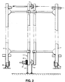
- a vehicle chassis 10 is shown upon which is mounted a mounting/demounting winch system 11 comprising a traction means in the form of a chain or cable extending from the rear portion of the vehicle chassis to a forward portion between guide rails or channels 17 comprising a support frame secured to the vehicle chassis 10.
- the traction means is preferably an endless chain, driven electrically or hydraulically, but also possibly by means of a hand winch, if a suitable power supply is not available, or a combination of these according to the availability of suitable power sources, said chain passing over end sprockets or pulleys 12 and 13 secured to the support frame mounted on the chassis 10.
- the removable rear body 18 is provided with corresponded guide rails or channels 14 for slidably engaging the channels or rails 17 provided on the vehicle chassis.
- a rear roller 15 which may be detachable or retractable, is preferably provided to enable the rear body 18 to roll over the ground surface during mounting or demounting of the rear body.
- a coupling arrangement 16 is provided, firstly for enabling connection of a coupling 19 from the chain traction mechanism to be connected for raising and lowering the rear body onto the support frame, and secondly, for enabling such to be securely affixed at the forward end when positioned on the support frame ready for use.
- Rollers or wheels are preferably provided in said guide rails or channels 14 and/or 17 to enable the demountable rear body to roll smoothly on the support frame during mounting or demounting thereof.
- a coupling 19 comprising a fly-cable (see Fig. 1) the length of which corresponds to at least the height of the support frame above ground level and is preferably slightly longer to enable an amount of slack to be provided for coupling and uncoupling purposes.
- a second coupling to the rear body 18 is provided, to which a cable 21 is attached, which is wound onto a drum 22, associated with a dog clutch 23 mounted on the drive shaft of rear sprocket or pulley 12.
- This second cable 21 is attached to the forward end of the rear body following initially lifting on of the forward end of the rear body onto the guide rails 17, and as the rear body 18 is pulled onto the support frame, the cable 21 is paid out, with the dog clutch 23 disengaged.
- the dog clutch 23 For demounting the rear body, the dog clutch 23 is engaged and driven rearwardly together with the drive chain mechanism, the cable 21 acting to pull the vehicle body rearwardly and is then disengaged to enable the rear body to be lowered from the support frame by the fly-cable 19, attached to the drive chain and when the rear body has been lowered to the ground, the fly-cable is disconnected, the cables then can be secured and the vehicle may then be driven off, for example to collect an alternative rear body.
- the rear body 18 is provided with additional rollers at the forward end of the guide channels 14 to enable such to be manoeuvred to a limited extent, and indeed the provision of the guide rails or channels on the lower portion of the rear body 18 enables access for the forklift truck or the like, to enable such to be moved, for example within a vehicle depot or the like. Further, such a facility enables the body portions to be stored in a space saving manner, which can be particularly important where space is at a a premium. Thus, a single tractor or drive unit can be utilised with a variety of bodies, thereby minimising capital costs in a fleet situation.
- additional securing means may be provided, particularly in the front portion of the rear body which could be locked onto the vehicle chassis or sub-frame with a suitable locking pin or the like and, if necessary, connected up to hydraulic power take-off systems of the vehicle or electrical power supplies, as appropriate.
- such types of containers could equally be provided for loading onto the trailer of an articulated vehicle, preferably adapted as a low-loader to enable a number of such rear body portions to be transported large distances by road on such articulated vehicles and then again collected by smaller vehicles for local deliveries.
- a split winch mechanism in which the two halves of the winch can be driven either in the same direction or opposite directions to enable an loading and unloading sequence to be performed, in that when the two halves of the winch are rotated in opposite directions, a loop of cable can be provided for coupling to the front of a rear body to be mounted on the support frame, such that, when the winch is operated to take up the loop, the front end of the rear body is lifted onto the rear of the support frame and then pulled up onto the support frame.
- a vehicle is positioned in front of a rear body to be mounted and the fly-cable 19 is attached to the front of the rear body 18.
- the mounting/demounting chain winch mechanism 11 is activated to tighten the fly-cable thereby gradually raising the front portion of the rear body 18 off the ground, the rear portion being allowed to roll over the ground on the rear roller 15.
- the guide rails 14 are engaged with the side rails 17, initially over the rollers 20.
- the secondary coupling cable 21 is attached, with the dog clutch 23 disengaged and the winch mechanism 11 continues to draw the rear body forwardly.
- the winch mechanism 11 is reversed and with the dog clutch 23 engaged, the cable 21 is progressively rewound back onto drum 22, displacing the rear body rearwardly and as the chain drive progresses rearwardly in concert therewith, as the centre of gravity of the rear body moves rearwardly, such progressively pivots about the rear rollers 20 under the control of the fly-cable 19, until the rear roller 15 engages the ground.
- the rear body 18 is progressively pulled back until such reaches a point at which the secondary coupling cable 21 can be detached and then the chain winch continues to gradually lower the front portion of the rear body to the ground, the fly-cable 19 then being disconnected to enable the vehicle to drive away.
Landscapes
- Engineering & Computer Science (AREA)
- Transportation (AREA)
- Mechanical Engineering (AREA)
- Motor Or Generator Frames (AREA)
- Connection Of Motors, Electrical Generators, Mechanical Devices, And The Like (AREA)
- Body Structure For Vehicles (AREA)
- Manufacture Of Motors, Generators (AREA)
- Arrangement Or Mounting Of Propulsion Units For Vehicles (AREA)
- Vehicle Cleaning, Maintenance, Repair, Refitting, And Outriggers (AREA)
- Soft Magnetic Materials (AREA)
- Compositions Of Oxide Ceramics (AREA)
- Glass Compositions (AREA)
Claims (9)
- Système d'échange de carrosserie de véhicule pour des véhicules commerciaux ou de marchandises, comprenant un cadre de support pouvant être fixé à un châssis de véhicule, ou d'un seul tenant avec ce dernier, ou monté sur un véhicule, des moyens montés sur le cadre de support ou le châssis de véhicule, pour permettre le montage d'une carrosserie arrière sur ledit cadre de support, ou son démontage dudit cadre de support, et des moyens pour fixer solidement ladite carrosserie arrière audit cadre de support, les moyens de montage/démontage comprenant un mécanisme à treuil (11) comprenant une chaîne ou câble sans fin d'entraînement incluant un premier élément d'accouplement comprenant un câble volant (19) ou une chaîne fixée à ladite chaîne ou câble sans fin dudit mécanisme à treuil (11), et pouvant être fixé à une extrémité avant (16) de la carrosserie arrière, ledit câble volant (19) ou chaîne étant d'une longueur correspondant à au moins la hauteur du cadre de support au-dessus du niveau du sol, pour accouplement à ladite carrosserie arrière (18) pour permettre à cette dernière d'être respectivement soulevée à partir du sol ou d'être abaissée vers le sol pendant une opération de montage ou de démontage, et caractérisé par un second moyen d'accouplement (21), monté sur le cadre de support ou châssis du véhicule, comprenant un second câble, pouvant être entraîné, de manière sélective, par ladite chaîne sans fin ou câble d'entraînement par l'intermédiaire d'un mécanisme d'embrayage (23), et qui peut être fixé à ladite extrémité avant (16) de ladite carrosserie arrière pour permettre le déplacement arrière de la carrosserie à partir du cadre de support au moyen de la chaîne ou câble sans fin du mécanisme à treuil (11) pour permettre le démontage de cette dernière.
- Système d'échange de carrosserie de véhicule selon la revendication 1, dans lequel le cadre de support comprend au moins deux rails ou profilés de guidage (17) pour recevoir et guider des profilés ou rails de guidage correspondants (14) d'une carrosserie arrière (18).
- Système d'échange de carrosserie de véhicule selon la revendication 2, dans lequel des rouleaux ou roues (20) sont disposés dans lesdits rails ou profilés de guidage (14, 17) du cadre de support ou de la carrosserie arrière démontable pour permettre à la carrosserie arrière (18) de rouler doucement sur le cadre de support pendant le montage ou le démontage de cette dernière.
- Système d'échange de carrosserie de véhicule selon l'une quelconque des revendications précédentes, dans lequel le mécanisme à treuil (11) est entraîné soit par un treuil manuel soit par des moteurs électriques ou hydrauliques ou par une combinaison de ces derniers selon la disponibilité de sources de courant appropriées.
- Système d'échange de carrosserie de véhicule selon l'une quelconque des revendications précédentes, dans lequel des moyens de verrouillage sont prévus en étant fixés soit à la carrosserie arrière (18) soit au châssis du véhicule (10) pour permettre à la carrosserie arrière d'être solidement fixée au véhicule, lors de l'utilisation.
- Système d'échange de carrosserie de véhicule selon l'une quelconque des revendications précédentes, dans lequel des rouleaux sont disposés au niveau de l'arrière du cadre de support pour faciliter le montage ou le démontage de la carrosserie arrière (18).
- Système d'échange de carrosserie de véhicule selon l'une quelconque des revendications précédentes, dans lequel des rouleaux ou roues arrière (15) sont disposés sur la carrosserie arrière (18) pour permettre à cette dernière de rouler sur le sol pendant les opérations de montage ou de démontage.
- Système d'échange de carrosserie de véhicule selon l'une quelconque des revendications précédentes, dans lequel ledit mécanisme d'embrayage est un embrayage à griffes (23) monté sur un arbre commun à l'entraînement du mécanisme à chaîne sans fin.
- Système d'échange de carrosserie de véhicule selon la revendication 1, dans lequel le mécanisme à treuil à câble est constitué par un double treuil, au moyen duquel les deux moitiés du treuil peuvent être tournées dans des sens opposés, de sorte qu'une boucle de câble peut être prévue pour un accouplement à l'avant d'une carrosserie arrière, de manière que lorsque le treuil est mis en oeuvre pour enrouler la boucle, l'extrémité avant de la carrosserie arrière est soulevée sur l'arrière du cadre de support et est ensuite tirée sur le cadre de support.
Applications Claiming Priority (3)
| Application Number | Priority Date | Filing Date | Title |
|---|---|---|---|
| GB8927667 | 1989-12-07 | ||
| GB898927667A GB8927667D0 (en) | 1989-12-07 | 1989-12-07 | A body replacement system for motor vehicles |
| PCT/GB1990/001915 WO1991008925A1 (fr) | 1989-12-07 | 1990-12-07 | Systeme de remplacement de la carrosserie de vehicules a moteur |
Publications (2)
| Publication Number | Publication Date |
|---|---|
| EP0504246A1 EP0504246A1 (fr) | 1992-09-23 |
| EP0504246B1 true EP0504246B1 (fr) | 1996-09-11 |
Family
ID=10667566
Family Applications (1)
| Application Number | Title | Priority Date | Filing Date |
|---|---|---|---|
| EP91900893A Expired - Lifetime EP0504246B1 (fr) | 1989-12-07 | 1990-12-07 | Systeme de chargement et dechargement pour vehicules a moteur |
Country Status (12)
| Country | Link |
|---|---|
| EP (1) | EP0504246B1 (fr) |
| JP (1) | JPH05502198A (fr) |
| KR (1) | KR920703362A (fr) |
| AT (1) | ATE142570T1 (fr) |
| AU (1) | AU637862B2 (fr) |
| BR (1) | BR9007903A (fr) |
| CA (1) | CA2070397A1 (fr) |
| DE (1) | DE69028551T2 (fr) |
| FI (1) | FI922630A7 (fr) |
| GB (2) | GB8927667D0 (fr) |
| HU (1) | HUT66145A (fr) |
| WO (1) | WO1991008925A1 (fr) |
Families Citing this family (3)
| Publication number | Priority date | Publication date | Assignee | Title |
|---|---|---|---|---|
| AU2003203469A1 (en) * | 2002-04-17 | 2003-11-06 | Lance Albert Lunson | Mounting Apparatus |
| GB0809195D0 (en) * | 2008-05-21 | 2008-06-25 | Ritson Peter A | Demountable vehicle body system |
| KR101983360B1 (ko) * | 2018-12-04 | 2019-05-28 | (주)하나로특장 | 유지보수가 용이한 랜딩 롤러 |
Citations (1)
| Publication number | Priority date | Publication date | Assignee | Title |
|---|---|---|---|---|
| GB2181715A (en) * | 1985-10-21 | 1987-04-29 | Ark Bv De | Loading and unloading load platforms on to vehicles |
Family Cites Families (4)
| Publication number | Priority date | Publication date | Assignee | Title |
|---|---|---|---|---|
| US3229839A (en) * | 1964-09-04 | 1966-01-18 | Quadramics Inc | Loading and unloading winch-system for traction vehicles |
| GB1159305A (en) * | 1967-04-05 | 1969-07-23 | Dobson Ltd W E & F | Improvements in or relating to Transferable Vehicle Goods Containers |
| FR2156988A5 (fr) * | 1971-10-13 | 1973-06-01 | Caen Atel Constr Metal | |
| FR2239407A1 (en) * | 1973-08-01 | 1975-02-28 | Locaner | Lift assembly for container fitting on flat bed lorry - cable passes under pulleys at front of container to lorry winch |
-
1989
- 1989-12-07 GB GB898927667A patent/GB8927667D0/en active Pending
-
1990
- 1990-12-07 HU HU9201882A patent/HUT66145A/hu unknown
- 1990-12-07 JP JP3501318A patent/JPH05502198A/ja active Pending
- 1990-12-07 EP EP91900893A patent/EP0504246B1/fr not_active Expired - Lifetime
- 1990-12-07 FI FI922630A patent/FI922630A7/fi not_active Application Discontinuation
- 1990-12-07 GB GB9026696A patent/GB2240751B/en not_active Revoked
- 1990-12-07 CA CA002070397A patent/CA2070397A1/fr not_active Abandoned
- 1990-12-07 AT AT91900893T patent/ATE142570T1/de not_active IP Right Cessation
- 1990-12-07 BR BR909007903A patent/BR9007903A/pt unknown
- 1990-12-07 AU AU69068/91A patent/AU637862B2/en not_active Ceased
- 1990-12-07 WO PCT/GB1990/001915 patent/WO1991008925A1/fr not_active Ceased
- 1990-12-07 KR KR1019920701337A patent/KR920703362A/ko not_active Withdrawn
- 1990-12-07 DE DE69028551T patent/DE69028551T2/de not_active Expired - Fee Related
Patent Citations (1)
| Publication number | Priority date | Publication date | Assignee | Title |
|---|---|---|---|---|
| GB2181715A (en) * | 1985-10-21 | 1987-04-29 | Ark Bv De | Loading and unloading load platforms on to vehicles |
Also Published As
| Publication number | Publication date |
|---|---|
| GB8927667D0 (en) | 1990-02-07 |
| JPH05502198A (ja) | 1993-04-22 |
| ATE142570T1 (de) | 1996-09-15 |
| AU637862B2 (en) | 1993-06-10 |
| EP0504246A1 (fr) | 1992-09-23 |
| KR920703362A (ko) | 1992-12-17 |
| HU9201882D0 (en) | 1992-12-28 |
| HUT66145A (en) | 1994-09-28 |
| DE69028551D1 (de) | 1996-10-17 |
| WO1991008925A1 (fr) | 1991-06-27 |
| FI922630A0 (fi) | 1992-06-05 |
| BR9007903A (pt) | 1992-09-08 |
| DE69028551T2 (de) | 1997-02-06 |
| GB2240751A (en) | 1991-08-14 |
| GB9026696D0 (en) | 1991-01-23 |
| FI922630L (fi) | 1992-06-05 |
| FI922630A7 (fi) | 1992-06-05 |
| GB2240751B (en) | 1993-12-22 |
| CA2070397A1 (fr) | 1991-06-08 |
| AU6906891A (en) | 1991-07-18 |
Similar Documents
| Publication | Publication Date | Title |
|---|---|---|
| US6354787B1 (en) | Double container trailer apparatus and method of use | |
| US8047758B2 (en) | Universal folding boom trailer | |
| US5246330A (en) | Apparatus for loading and unloading of two separate containers upon a vehicular body | |
| US4149643A (en) | Truck tow lift | |
| US20100215466A1 (en) | Loading and Unloading Arrangement for a Vehicle | |
| US20060182580A1 (en) | Truck container transport/storage system and method | |
| US5326215A (en) | Universal vehicular recovery and towing platform | |
| US8602712B2 (en) | Demountable vehicle body system | |
| EP0504246B1 (fr) | Systeme de chargement et dechargement pour vehicules a moteur | |
| GB2094262A (en) | Arrangement on a vehicle having a rotatable crane | |
| US8251394B2 (en) | Low rider saddle mount | |
| CN201189835Y (zh) | 自装卸式集装箱运输半挂车 | |
| GB2236518A (en) | Transport apparatus | |
| US6200085B1 (en) | Transport system for farm combines and other large vehicles | |
| RU2019451C1 (ru) | Транспортное средство | |
| SU1217698A1 (ru) | Транспортное средство дл перевозки крупногабаритных грузов | |
| DK202370171A1 (en) | Transport system and method for flat-bottomed containers | |
| DK202430040A1 (en) | Flat-bottomed containers and transport system and method for handling such containers | |
| US20200247624A1 (en) | Trailer conveyor system and method | |
| CA2550613A1 (fr) | Systeme d'entreposage mobile | |
| JPH082309A (ja) | 貨物自動車における牽引装置 |
Legal Events
| Date | Code | Title | Description |
|---|---|---|---|
| PUAI | Public reference made under article 153(3) epc to a published international application that has entered the european phase |
Free format text: ORIGINAL CODE: 0009012 |
|
| 17P | Request for examination filed |
Effective date: 19920626 |
|
| AK | Designated contracting states |
Kind code of ref document: A1 Designated state(s): AT BE CH DE DK ES FR GB GR IT LI LU NL SE |
|
| 17Q | First examination report despatched |
Effective date: 19930930 |
|
| GRAH | Despatch of communication of intention to grant a patent |
Free format text: ORIGINAL CODE: EPIDOS IGRA |
|
| GRAH | Despatch of communication of intention to grant a patent |
Free format text: ORIGINAL CODE: EPIDOS IGRA |
|
| GRAA | (expected) grant |
Free format text: ORIGINAL CODE: 0009210 |
|
| AK | Designated contracting states |
Kind code of ref document: B1 Designated state(s): AT BE CH DE DK ES FR GB GR IT LI LU NL SE |
|
| PG25 | Lapsed in a contracting state [announced via postgrant information from national office to epo] |
Ref country code: AT Effective date: 19960911 Ref country code: DK Effective date: 19960911 Ref country code: NL Free format text: LAPSE BECAUSE OF FAILURE TO SUBMIT A TRANSLATION OF THE DESCRIPTION OR TO PAY THE FEE WITHIN THE PRESCRIBED TIME-LIMIT Effective date: 19960911 Ref country code: LI Effective date: 19960911 Ref country code: ES Free format text: THE PATENT HAS BEEN ANNULLED BY A DECISION OF A NATIONAL AUTHORITY Effective date: 19960911 Ref country code: CH Effective date: 19960911 Ref country code: BE Effective date: 19960911 Ref country code: FR Effective date: 19960911 Ref country code: GR Free format text: LAPSE BECAUSE OF FAILURE TO SUBMIT A TRANSLATION OF THE DESCRIPTION OR TO PAY THE FEE WITHIN THE PRESCRIBED TIME-LIMIT Effective date: 19960911 |
|
| REF | Corresponds to: |
Ref document number: 142570 Country of ref document: AT Date of ref document: 19960915 Kind code of ref document: T |
|
| REF | Corresponds to: |
Ref document number: 69028551 Country of ref document: DE Date of ref document: 19961017 |
|
| ITF | It: translation for a ep patent filed | ||
| PG25 | Lapsed in a contracting state [announced via postgrant information from national office to epo] |
Ref country code: SE Effective date: 19961211 |
|
| PG25 | Lapsed in a contracting state [announced via postgrant information from national office to epo] |
Ref country code: LU Free format text: LAPSE BECAUSE OF NON-PAYMENT OF DUE FEES Effective date: 19961231 |
|
| EN | Fr: translation not filed | ||
| NLV1 | Nl: lapsed or annulled due to failure to fulfill the requirements of art. 29p and 29m of the patents act | ||
| REG | Reference to a national code |
Ref country code: CH Ref legal event code: PL |
|
| PLBE | No opposition filed within time limit |
Free format text: ORIGINAL CODE: 0009261 |
|
| STAA | Information on the status of an ep patent application or granted ep patent |
Free format text: STATUS: NO OPPOSITION FILED WITHIN TIME LIMIT |
|
| PG25 | Lapsed in a contracting state [announced via postgrant information from national office to epo] |
Ref country code: DE Effective date: 19970902 |
|
| 26N | No opposition filed | ||
| REG | Reference to a national code |
Ref country code: GB Ref legal event code: 732E |
|
| REG | Reference to a national code |
Ref country code: GB Ref legal event code: IF02 |
|
| PG25 | Lapsed in a contracting state [announced via postgrant information from national office to epo] |
Ref country code: IT Free format text: LAPSE BECAUSE OF NON-PAYMENT OF DUE FEES;WARNING: LAPSES OF ITALIAN PATENTS WITH EFFECTIVE DATE BEFORE 2007 MAY HAVE OCCURRED AT ANY TIME BEFORE 2007. THE CORRECT EFFECTIVE DATE MAY BE DIFFERENT FROM THE ONE RECORDED. Effective date: 20051207 |
|
| PGFP | Annual fee paid to national office [announced via postgrant information from national office to epo] |
Ref country code: GB Payment date: 20081223 Year of fee payment: 19 |
|
| GBPC | Gb: european patent ceased through non-payment of renewal fee |
Effective date: 20091207 |
|
| PG25 | Lapsed in a contracting state [announced via postgrant information from national office to epo] |
Ref country code: GB Free format text: LAPSE BECAUSE OF NON-PAYMENT OF DUE FEES Effective date: 20091207 |