EP0504580A2 - Dispositif de pressage et machine de soudage en bout par étincelage équipée avec un tel dispositif - Google Patents
Dispositif de pressage et machine de soudage en bout par étincelage équipée avec un tel dispositif Download PDFInfo
- Publication number
- EP0504580A2 EP0504580A2 EP92102165A EP92102165A EP0504580A2 EP 0504580 A2 EP0504580 A2 EP 0504580A2 EP 92102165 A EP92102165 A EP 92102165A EP 92102165 A EP92102165 A EP 92102165A EP 0504580 A2 EP0504580 A2 EP 0504580A2
- Authority
- EP
- European Patent Office
- Prior art keywords
- press
- pressing
- unit
- force absorption
- machine frame
- Prior art date
- Legal status (The legal status is an assumption and is not a legal conclusion. Google has not performed a legal analysis and makes no representation as to the accuracy of the status listed.)
- Withdrawn
Links
- 238000003466 welding Methods 0.000 title claims abstract description 12
- 238000010521 absorption reaction Methods 0.000 claims abstract description 15
- 230000000087 stabilizing effect Effects 0.000 claims description 6
- 238000005452 bending Methods 0.000 claims description 2
- 238000000034 method Methods 0.000 claims description 2
- 239000000725 suspension Substances 0.000 claims description 2
- 230000001105 regulatory effect Effects 0.000 claims 1
- 238000006243 chemical reaction Methods 0.000 abstract description 3
- 238000003801 milling Methods 0.000 abstract description 3
- 238000010276 construction Methods 0.000 description 2
- 238000006073 displacement reaction Methods 0.000 description 1
- 238000007493 shaping process Methods 0.000 description 1
Images
Classifications
-
- B—PERFORMING OPERATIONS; TRANSPORTING
- B30—PRESSES
- B30B—PRESSES IN GENERAL
- B30B15/00—Details of, or accessories for, presses; Auxiliary measures in connection with pressing
- B30B15/06—Platens or press rams
- B30B15/068—Drive connections, e.g. pivotal
-
- B—PERFORMING OPERATIONS; TRANSPORTING
- B30—PRESSES
- B30B—PRESSES IN GENERAL
- B30B15/00—Details of, or accessories for, presses; Auxiliary measures in connection with pressing
- B30B15/04—Frames; Guides
- B30B15/047—C-shaped frames
Definitions
- the invention relates to a pressing device according to the preamble of patent claim 1 and a flash butt welding machine equipped therewith according to the preamble of patent claim 8.
- the press ram-containing press units in frames with an O-frame shape were used to absorb force from one press unit to another, as described, for. B. in Dubbel, "Taschenbuch für Maschinenbau, 16th edition, p. S35.
- the O-frame shape makes access to the press rams difficult and thus the introduction of the workpiece parts to be pressed between the press rams.
- so-called C-frame forms were used, which are open on one side and thus allow easy access to the press rams.
- the press units, each with a press ram were attached to the free legs of the C-frame shape. Due to the high feed forces during the pressing process, the C-frame shape had to be designed to be disproportionately reinforced in order to achieve a reasonably flat pressing or pressing of the workpiece parts, since the entire C-frame shape warped.
- the invention has for its object to provide a pressing device of the type mentioned, which allows a flawless, uniform flat pressing together of workpiece parts.
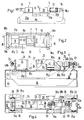
- the basic structure of a pressing device is described below with reference to FIGS. 1 and 2 .
- the pressing device can e.g. B. for uniform flat Pressing together two workpiece parts can be used.
- the pressing device according to the invention can also be used to guide a drill, a milling cutter, a punch for plastic workpiece shaping, etc. without tilting perpendicularly to the workpiece surface on or into it under high manpower.
- a flash-butt welding machine with a press device according to the invention is then described as a preferred embodiment with reference to FIGS. 1 and 2 .
- the pressing device shown in Figure 1 with two pressing units 3 and 5 has a machine frame 1, with which the pressing unit 3 is firmly connected.
- the pressing unit 5 is mounted so that it can be displaced in the feed direction 7 against the pressing unit 3 on two horizontal guide rails 8a and 8b which run parallel to one another and are fastened to the machine frame 1 .
- Each of the press units 3 and 5 has a press die holder 9 or 10 as a supporting means for a press die 11 or 12, which are designed as workpiece holders.
- the press unit 5 has a piston-cylinder unit 13, the piston rod 13a of which is rigidly connected to the stamp holder 10 .
- a joint 15 or 16 is flanged.
- the joint axes of the joints 15 and 16 are horizontal, perpendicular to the direction of advance 7 of the pressing unit 5 , as shown in FIG. 1 .
- the press ram holder 9 is firmly connected to the machine frame 1 .
- the force absorption of the reaction forces from one press unit 3 to the other press unit 5 takes place through a C-shaped force absorption unit, formed from a Pair of C-shaped force receiving elements 17a and 17b, the end regions of the legs 18a and 18b are mounted on the joint 15 and 16 and are connected to one another by the joint axis of the joints 15 and 16 .
- the two force absorption elements 17a and 17b are arranged horizontally and lie parallel to one another.
- a joint (not shown) can also be arranged between the piston rod 13a and the press die holder 10 .
- a bendable stabilizing plate is advantageously arranged between the cylinder 13b and the machine frame 1 , as described below for another construction.
- FIGS. 3 and 4 A variant of the pressing device according to the invention as a pressing device in a flash butt welding machine is shown in FIGS. 3 and 4 .
- Analogous to the above-described pressing device is on the machine frame 20 of the flash-butt welding in figure 3 left a pressing unit 21 analogous to the press unit 3 is rigidly connected by screws 22 to the machine frame 20th The other press unit 23 is arranged to be displaceable in the feed direction 7 to the press unit 21 .
- the press unit 21 has a press die holder 24 as a suspension element, with which it is screwed onto the machine frame 20 .
- a press die 25 Arranged on the press die holder 24 is a press die 25 designed as an electrode and workpiece holder for one of the workpiece parts to be welded to one another, and a joint 26 designed analogously to the joint 16, likewise with a horizontal joint axis perpendicular to the feed direction 7 .
- the press unit 23 also has a press ram 27 designed as an electrode and workpiece holder for the other workpiece part, which is held by a press ram holder 28 .
- the press ram holder 28 is held in the feed direction 7 by three linear bearings 19a, b and c attached to the machine frame 20 .
- Three bearings 19a , 19b and 19c are used in order to obtain a very precise guide for a straight feed of the workpiece parts to be welded.
- the pressing unit 23 has a double piston-cylinder unit 29 as a drive device for the feed force required for welding, the piston 30a of the one piston-cylinder unit 30 of the double piston-cylinder unit 29 being pivotable with a bearing 31 , the axis of which runs parallel to the axis of the joint 26 , is mounted on the press die holder 28 .
- the piston head on the piston 32a of the other piston-cylinder unit 32 has a joint 33 , the axis of which is arranged parallel to the axis of the joint 26 .
- the two cylinder housings 30b and 32b of the two piston-cylinder units 30 and 32 are firmly and rigidly connected to one another at the bottom.
- One of the three linear bearings 19a and 19b is arranged on each side of the bearing 31 , and the third bearing 19c is arranged centrally below the joint 26 .
- the press ram holder 28 is fastened on a carriage 34 and is displaceably arranged on the machine frame 20 with the bearings 19a, 19b and 19c .
- the carriage 34 is movable in feeding direction 7 in a direction shown in Figure 4 the frame opening 35 of the machine frame 20th
- the force absorption of the reaction forces from one press unit 21 to the other press unit 23 also takes place here by means of a C-shaped, however U-shaped cross-section and integrally formed force take-up unit 36, the end regions of its legs 40a and 40b via the joints 26 and 33 with the press units 21 and 23 are articulated.
- the two legs 40a and 40b of the force absorption unit 36 which act on the joints 26 and 33 , each reach through a machine frame opening 35a and 35b and through a machine frame recess 35c and 35d in the region of the joints 26 and 33 .
- the housing surrounding the joint 33 is connected to the machine frame 20 via a stabilizing plate 37 .
- the stabilizing plate 37 can be bent elastically in the feed direction 7 by a small force. Perpendicular to the feed direction 7 , however, it has a very high stability against deformation.
- the stabilizing plate 37 prevents a force of the two piston-cylinder units 30 and 32 whose buckling out of the feed axis 38 of the two press units 21 and 23.
- the piston-cylinder unit 30 is used to carry out the large feed feed path of the two press rams 25 and 27 against one another in the case of workpiece parts inserted into the press rams 25 and 27 .
- a measuring potentiometer 39 which is connected to a control device (not shown), is arranged between the cylinder 32b and a ring 41 fixedly attached to the piston 32a .
- the stabilizing plate 37 Since the deformation of the force absorption unit 36 under load in relation to the machine frame 20 is small, the stabilizing plate 37 is only slightly elastically deflected.
- crank drives or eccentrics can also be used.
- the press device can be used wherever the two press rams have to be moved exactly in a straight line under high pressures. You can thus also in machine tools such. B. drills, milling machine, can be used in a variety of presses, etc.
Landscapes
- Engineering & Computer Science (AREA)
- Mechanical Engineering (AREA)
- Jigs For Machine Tools (AREA)
- Gripping Jigs, Holding Jigs, And Positioning Jigs (AREA)
- Butt Welding And Welding Of Specific Article (AREA)
- Press Drives And Press Lines (AREA)
Applications Claiming Priority (2)
| Application Number | Priority Date | Filing Date | Title |
|---|---|---|---|
| CH84791 | 1991-03-20 | ||
| CH847/91 | 1991-03-20 |
Publications (2)
| Publication Number | Publication Date |
|---|---|
| EP0504580A2 true EP0504580A2 (fr) | 1992-09-23 |
| EP0504580A3 EP0504580A3 (en) | 1993-02-03 |
Family
ID=4196600
Family Applications (1)
| Application Number | Title | Priority Date | Filing Date |
|---|---|---|---|
| EP19920102165 Withdrawn EP0504580A3 (en) | 1991-03-20 | 1992-02-10 | Press device and flash butt-welding machine equipped with such a device |
Country Status (2)
| Country | Link |
|---|---|
| EP (1) | EP0504580A3 (fr) |
| JP (1) | JPH05123896A (fr) |
Cited By (8)
| Publication number | Priority date | Publication date | Assignee | Title |
|---|---|---|---|---|
| EP0620095A3 (fr) * | 1993-03-20 | 1995-01-04 | Karl Hehl | Machine à mouler par injection, notamment machine à mouler par injection des matières plastiques. |
| EP0646448A1 (fr) * | 1993-09-30 | 1995-04-05 | Karl Hehl | Machine à mouler par injection pour traiter des matières plastifiables |
| US5578329A (en) * | 1993-03-20 | 1996-11-26 | Hehl; Karl | Injection molding machine for processing synthetic materials |
| EP0554068B2 (fr) † | 1992-01-31 | 2000-08-23 | Amir Ziv-Av | Unité de fermeture pour un dispositif de moulage par injection |
| US8658935B2 (en) | 2008-12-24 | 2014-02-25 | Chemetron-Railway Products, Inc. | Welding process with jerk compensation |
| CN105773231A (zh) * | 2016-05-10 | 2016-07-20 | 无为县宏喜体育用品有限公司 | 一种用于盘类零件钻孔用的固定夹紧装置 |
| US10040233B2 (en) | 2013-02-19 | 2018-08-07 | Husky Injection Molding Systems Ltd. | Actuator for a molding system |
| CN113953722A (zh) * | 2021-11-05 | 2022-01-21 | 苏州安嘉自动化设备有限公司 | 一种铜绞线铝棒对焊机 |
Families Citing this family (1)
| Publication number | Priority date | Publication date | Assignee | Title |
|---|---|---|---|---|
| DE102007063653B4 (de) * | 2007-10-22 | 2011-01-27 | Zhafir Plastics Machinery Gmbh | Spritzgießmaschine mit Schutzverkleidung |
Family Cites Families (3)
| Publication number | Priority date | Publication date | Assignee | Title |
|---|---|---|---|---|
| US2580078A (en) * | 1945-05-28 | 1951-12-25 | Denison Eng Co | Press mechanism |
| NL8801799A (nl) * | 1988-07-14 | 1990-02-01 | Brouwer & Co Holding | Gereedschapsmachine met c-vormig frame. |
| SE462790B (sv) * | 1988-12-22 | 1990-09-03 | Hydro Flex Ab | Stativ till en gappress |
-
1992
- 1992-02-10 EP EP19920102165 patent/EP0504580A3/de not_active Withdrawn
- 1992-03-19 JP JP11063292A patent/JPH05123896A/ja active Pending
Cited By (9)
| Publication number | Priority date | Publication date | Assignee | Title |
|---|---|---|---|---|
| EP0554068B2 (fr) † | 1992-01-31 | 2000-08-23 | Amir Ziv-Av | Unité de fermeture pour un dispositif de moulage par injection |
| EP0620095A3 (fr) * | 1993-03-20 | 1995-01-04 | Karl Hehl | Machine à mouler par injection, notamment machine à mouler par injection des matières plastiques. |
| US5578329A (en) * | 1993-03-20 | 1996-11-26 | Hehl; Karl | Injection molding machine for processing synthetic materials |
| EP0646448A1 (fr) * | 1993-09-30 | 1995-04-05 | Karl Hehl | Machine à mouler par injection pour traiter des matières plastifiables |
| US5700502A (en) * | 1993-09-30 | 1997-12-23 | Hehl; Karl | Injection molding machine for processing synthetic materials |
| US8658935B2 (en) | 2008-12-24 | 2014-02-25 | Chemetron-Railway Products, Inc. | Welding process with jerk compensation |
| US10040233B2 (en) | 2013-02-19 | 2018-08-07 | Husky Injection Molding Systems Ltd. | Actuator for a molding system |
| CN105773231A (zh) * | 2016-05-10 | 2016-07-20 | 无为县宏喜体育用品有限公司 | 一种用于盘类零件钻孔用的固定夹紧装置 |
| CN113953722A (zh) * | 2021-11-05 | 2022-01-21 | 苏州安嘉自动化设备有限公司 | 一种铜绞线铝棒对焊机 |
Also Published As
| Publication number | Publication date |
|---|---|
| JPH05123896A (ja) | 1993-05-21 |
| EP0504580A3 (en) | 1993-02-03 |
Similar Documents
| Publication | Publication Date | Title |
|---|---|---|
| EP2498928B1 (fr) | Installation d'usinage, notamment pour le formage libre avec un manipulateur de pièce et d'outil intégré | |
| DE202020100177U1 (de) | Ultraschallschweißmaschine | |
| EP2197660B1 (fr) | élément de translation mobile et transmission par clavette avec un tel élément de translation mobile | |
| EP4117837B1 (fr) | Presse plieuse | |
| AT509980B1 (de) | Fertigungsanlage mit werkzeugspeicher | |
| DE69321827T2 (de) | Kombiniertes schneid- und schweissverfahren zur herstellung struktureller produkte, gerät zur durchführung eines solchen verfahrens und mittels dieses verfahrens hergestellter produkte | |
| DE102010028032B4 (de) | Werkzeugmaschine mit zusätzlichem Zuganker | |
| EP0532853B1 (fr) | Dispositif pour le soudage longitudinal des tôles | |
| WO2006136404A1 (fr) | Dispositif de fixation d'outil pour mecanisme a clavette | |
| DE102014212527B3 (de) | Stauchvorrichtung für eine Kettenschweißmaschine sowie Kettenschweißmaschine | |
| AT510719B1 (de) | Biegewerkzeug für das freiformbiegen von blechen | |
| AT510840B1 (de) | Fertigungsanlage mit hilfsvorrichtung zur zwischenpositionierung von werkstücken | |
| DE3434470A1 (de) | Biegepresse | |
| WO2004080627A1 (fr) | Machine plieuse destinee notamment a des tables de soudage ou de serrage, table de soudage et table de serrage | |
| EP0076783B1 (fr) | Machine à cintrer des tubes et des barres profilés | |
| DE2851384C2 (fr) | ||
| EP2845663B1 (fr) | Presse plieuse avec un outil de cintrage composé de plusieurs éléments d'outil | |
| DE20113032U1 (de) | Schweißmaschine, insbesondere Widerstandsschweißmaschine | |
| CH679753A5 (fr) | ||
| CH680344A5 (fr) | ||
| EP1344603A1 (fr) | Unité de déplacement d'une machine-outil et une machine-outil avec cette unité de déplacement | |
| DE3432546A1 (de) | Profilstahlschere | |
| AT403261B (de) | Mehrzweckmaschine zur metallbearbeitung | |
| EP1852230A1 (fr) | Presse à carcasses | |
| DE2022405C3 (de) | Reibungsschweißmaschine |
Legal Events
| Date | Code | Title | Description |
|---|---|---|---|
| PUAI | Public reference made under article 153(3) epc to a published international application that has entered the european phase |
Free format text: ORIGINAL CODE: 0009012 |
|
| AK | Designated contracting states |
Kind code of ref document: A2 Designated state(s): DE ES FR GB IT SE |
|
| PUAL | Search report despatched |
Free format text: ORIGINAL CODE: 0009013 |
|
| AK | Designated contracting states |
Kind code of ref document: A3 Designated state(s): DE ES FR GB IT SE |
|
| STAA | Information on the status of an ep patent application or granted ep patent |
Free format text: STATUS: THE APPLICATION IS DEEMED TO BE WITHDRAWN |
|
| 18D | Application deemed to be withdrawn |
Effective date: 19930804 |