EP0504581A2 - Verfahren und Vorrichtung zur Behandlung von pulverförmiger Kohle in einer Einspritzanlage für feste Brennstoffe - Google Patents
Verfahren und Vorrichtung zur Behandlung von pulverförmiger Kohle in einer Einspritzanlage für feste Brennstoffe Download PDFInfo
- Publication number
- EP0504581A2 EP0504581A2 EP92102168A EP92102168A EP0504581A2 EP 0504581 A2 EP0504581 A2 EP 0504581A2 EP 92102168 A EP92102168 A EP 92102168A EP 92102168 A EP92102168 A EP 92102168A EP 0504581 A2 EP0504581 A2 EP 0504581A2
- Authority
- EP
- European Patent Office
- Prior art keywords
- airlock
- coal
- silo
- depressurization
- gas
- Prior art date
- Legal status (The legal status is an assumption and is not a legal conclusion. Google has not performed a legal analysis and makes no representation as to the accuracy of the status listed.)
- Granted
Links
Images
Classifications
-
- F—MECHANICAL ENGINEERING; LIGHTING; HEATING; WEAPONS; BLASTING
- F23—COMBUSTION APPARATUS; COMBUSTION PROCESSES
- F23K—FEEDING FUEL TO COMBUSTION APPARATUS
- F23K3/00—Feeding or distributing of lump or pulverulent fuel to combustion apparatus
- F23K3/02—Pneumatic feeding arrangements, i.e. by air blast
-
- C—CHEMISTRY; METALLURGY
- C21—METALLURGY OF IRON
- C21B—MANUFACTURE OF IRON OR STEEL
- C21B5/00—Making pig-iron in the blast furnace
- C21B5/001—Injecting additional fuel or reducing agents
- C21B5/003—Injection of pulverulent coal
-
- Y—GENERAL TAGGING OF NEW TECHNOLOGICAL DEVELOPMENTS; GENERAL TAGGING OF CROSS-SECTIONAL TECHNOLOGIES SPANNING OVER SEVERAL SECTIONS OF THE IPC; TECHNICAL SUBJECTS COVERED BY FORMER USPC CROSS-REFERENCE ART COLLECTIONS [XRACs] AND DIGESTS
- Y10—TECHNICAL SUBJECTS COVERED BY FORMER USPC
- Y10S—TECHNICAL SUBJECTS COVERED BY FORMER USPC CROSS-REFERENCE ART COLLECTIONS [XRACs] AND DIGESTS
- Y10S48/00—Gas: heating and illuminating
- Y10S48/04—Powdered fuel injection
Definitions
- the present invention relates to a method for treating powdered coal in a solid fuel injection installation, comprising a silo for storing powdered coal, at least one airlock connected to the pneumatic coal transport circuit, at least one filtering screen connected between each airlock and the silo, a source of inert gas under pressure for the pressurization of each airlock and the formation of the pneumatic propulsion current of the coal and a circuit for pressure equalization and depressurization of each airlock through a filter.
- the invention also relates to a device for implementing this method.
- the humidity level poses a number of problems in the storage silo.
- the drying gas accumulates a large quantity of water vapor which, as it cools in the silo, condenses above the mass and is responsible for agglomeration. and encrusting the coal powder.
- the object of the present invention is to provide a new process and a new device in which the risks of condensation of water vapor are significantly reduced.
- the process proposed by the present invention is essentially characterized in that the major part of the inert depressurization gas of each airlock is subjected to a filtration operation before being injected into the bottom of the storage silo in the mass of coal and to be released through a filter at the top of the silo above the level of coal and in that the residual part of the inert depressurization gas is deflected directly towards the top of the storage silo.
- the filtration operation preferably includes a dynamic filtration phase and a static filtration phase.
- the filtration means can be purged and cleaned with inert gas which, at the outlet of the filtration means, is directed through the screen (s) with the carbon powder in the airlock (s) during their filling.
- the invention allows advantageous use to be made of the availability of this fairly dry and inert gas to improve the thermal and hygrometric conditions in the silo, both within the mass of coal and above it. In fact, by injecting this inert gas under pressure into the bottom of the silo, a multiple beneficial effect is achieved.
- the passage of gas through the mass of the coal powder also has a beneficial effect on its consistency, thanks to its loosening action.
- the device for implementing the invention is characterized in that the pressure equalization and depressurization circuit of each airlock comprises a primary circuit connecting the top of the storage silo to each airlock and a secondary circuit connecting the bottom from the storage silo, through a filtration station, to each airlock.
- the filtration station may include a cyclone and a filter plate. Both the cyclone and the filter plate can be connected to at least one screen on the one hand and to an inert gas cleaning circuit on the other.
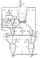
- References 2 and 4 designate two airlocks operating alternately to lock powdered coal in a pneumatic transport pipe 6 under the action of a gas. of inert propulsion injected, under pressure, into each airlock 2 and 4 from one or two sources of pressurized gas not shown and whose pressure is measured and monitored by pressure sensors 8, 10.
- the airlocks 2 and 4 are supplied with coal powder from a storage silo 12 through screens 14, 16 containing means for filtering the coal powder.
- each of the airlocks 2, 4 is connected through a primary circuit 18, 20 to the top of the storage silo 12 where the aeration is carried out through a filter 22 located on the silo 12.
- each of the two airlocks is also connected through a secondary circuit 24 at the bottom of the silo 12.
- This secondary circuit 24 passes through a filtration station which may consist of a cyclone 26 and a filter plate 28.
- the cyclone 26 and the filter plate 28 can be connected by the opening of a valve 30 to a source of inert gas 32 intended for cleaning the cyclone 26 and the filter plate 28.
- the cyclone 26 and the filter plate 28 can also be put in communication with one or both screens 14, 16 by the opening of valves 34, 36, which makes it possible to use the cleaning residues by sending them in the screen 14 (and / or in the screen 16 ) and use the pressure of the cleaning gas as a propellant to facilitate filling the airlocks 2 and 4.
- When cleaning the filtration station it is disconnected from the silo 12 by closing a valve 38.
- the two airlocks can be connected to their depressurization circuit 18, 20, 24 by automatic closing valves 40, 42 while the control of the operation of the primary and secondary circuits is carried out by automatic adjustment valves 44, 46, d 'a part and the automatic adjustment valve 48 in the secondary circuit 24, on the other hand.
- These valves 44, 46, 48 are valves the opening of which is adjusted automatically as a function of the pressure detected by the sensors 8 or 10 to ensure a determined and constant flow.
- the remains of coal powder entrained by the gas in the secondary circuit 24 are, in part, deposited in the cyclone 26 and, in part, retained by the filter plate 28, while the inert gas, freed of remains of coal powder, is injected from the bottom into silo 12 to purge the water vapor.
- This injection is carried out through non-return sieves, not shown, incorporated in the wall of the silo 12 and capable of letting the gas pass and retaining the coal powder.
- These non-return screens therefore prevent the powder from leaving the silo 12 towards the circuit 24 and at the same time ensure a good distribution in the silo 12 of the depressurization gas coming from the circuit 24.
- the valve 48 is designed to be closed automatically when the pressure of the depressurization gas falls below a predetermined threshold corresponding to the minimum pressure required to pass through the secondary circuit 24 and the mass of coal in the silo 12.
- the valve 44 is designed to be opened automatically by the sensor 8 at this same pressure, so that the airlock 2 is automatically switched from the secondary circuit 24 to the primary circuit 18 and that the residual part of inert gas at low pressure is deflected towards the top of the silo 12 to be released through the filter 22.
- the airlock 2 is completely depressurized, it is disconnected from the two circuits 18 and 24 by closing the valve 40. From this moment can begin filling the airlock by opening valves, not shown, in the pipe connecting the airlock 2 to the silo 12.
- the remains of coal powder entrained by the rinsing gas in the cyclone 26 and the filter plate 28 are then mixed with the coal powder flowing from the silo 12 into the tank 14.
- the airlock 2 When the airlock 2 is full, it can be disconnected from the intermediate reservoir 14 and connected to the pneumatic transport line 6, while the empty airlock 4 undergoes the depressurization and filling operations as described above.
Landscapes
- Engineering & Computer Science (AREA)
- Chemical & Material Sciences (AREA)
- Combustion & Propulsion (AREA)
- Materials Engineering (AREA)
- Metallurgy (AREA)
- Organic Chemistry (AREA)
- Manufacturing & Machinery (AREA)
- Mechanical Engineering (AREA)
- General Engineering & Computer Science (AREA)
- Air Transport Of Granular Materials (AREA)
- Solid Fuels And Fuel-Associated Substances (AREA)
- Auxiliary Methods And Devices For Loading And Unloading (AREA)
- Filling Or Emptying Of Bunkers, Hoppers, And Tanks (AREA)
Applications Claiming Priority (2)
| Application Number | Priority Date | Filing Date | Title |
|---|---|---|---|
| LU87910 | 1991-03-20 | ||
| LU87910A LU87910A1 (fr) | 1991-03-20 | 1991-03-20 | Procede et dispositif de traitement de charbon en poudre dans une installation d'injection de combustibles solides |
Publications (3)
| Publication Number | Publication Date |
|---|---|
| EP0504581A2 true EP0504581A2 (de) | 1992-09-23 |
| EP0504581A3 EP0504581A3 (en) | 1993-01-27 |
| EP0504581B1 EP0504581B1 (de) | 1995-03-29 |
Family
ID=19731284
Family Applications (1)
| Application Number | Title | Priority Date | Filing Date |
|---|---|---|---|
| EP92102168A Expired - Lifetime EP0504581B1 (de) | 1991-03-20 | 1992-02-10 | Verfahren und Vorrichtung zur Behandlung von pulverförmiger Kohle in einer Einspritzanlage für feste Brennstoffe |
Country Status (9)
| Country | Link |
|---|---|
| US (1) | US5284187A (de) |
| EP (1) | EP0504581B1 (de) |
| CA (1) | CA2063279C (de) |
| DE (1) | DE69201812T2 (de) |
| ES (1) | ES2073199T3 (de) |
| LU (1) | LU87910A1 (de) |
| RU (1) | RU2062951C1 (de) |
| UA (1) | UA25927C2 (de) |
| ZA (1) | ZA921662B (de) |
Cited By (1)
| Publication number | Priority date | Publication date | Assignee | Title |
|---|---|---|---|---|
| CN103162306A (zh) * | 2011-12-14 | 2013-06-19 | 佛山市国保节能环保技术有限公司 | 煤粉远程输送和燃烧系统 |
Families Citing this family (9)
| Publication number | Priority date | Publication date | Assignee | Title |
|---|---|---|---|---|
| US7008459B1 (en) * | 1997-04-09 | 2006-03-07 | Arthur P. Fraas | Pretreatment process to remove oxygen from coal en route to a coal pyolysis process as a means of improving the quality of the hydrocarbon liquid product |
| US6079461A (en) * | 1998-08-17 | 2000-06-27 | The Heil Co. | Use of inert gas in transfer of comminuted product to tank |
| US6810929B1 (en) * | 2003-06-12 | 2004-11-02 | Ppg Industries Ohio, Inc. | Transportable container for fluidizable material and method |
| TW200900421A (en) * | 2006-10-10 | 2009-01-01 | Univation Tech Llc | Discharge system to remove solids from a vessel |
| FI124436B (fi) * | 2008-03-18 | 2014-08-29 | Maricap Oy | Menetelmä ja laitteisto pneumaattisessa materiaalinsiirtojärjestelmässä |
| WO2012138702A1 (en) | 2011-04-04 | 2012-10-11 | Proven Engineering And Technologies, Llc | Accurate dry bulk handling system and method of use |
| LU92916B1 (en) * | 2015-12-17 | 2017-07-13 | Wurth Paul Sa | Grinding and drying plant |
| JP7039795B2 (ja) * | 2018-02-23 | 2022-03-23 | 三菱重工業株式会社 | 粉体供給ホッパ加圧装置、ガス化炉設備およびガス化複合発電設備ならびに粉体供給ホッパ加圧装置の制御方法 |
| CN111232453A (zh) * | 2020-03-19 | 2020-06-05 | 马鞍山市天工科技股份有限公司 | 球形储煤仓智能防燃清堵装置 |
Family Cites Families (7)
| Publication number | Priority date | Publication date | Assignee | Title |
|---|---|---|---|---|
| US3775071A (en) * | 1971-06-20 | 1973-11-27 | Hydrocarbon Research Inc | Method for feeding dry coal to superatmospheric pressure |
| DE2434526C2 (de) * | 1974-07-18 | 1983-01-13 | Shell Internationale Research Maatschappij B.V., 2501 's-Gravenhage | Verfahren und Einrichtung zum Einführen feinzerteilten festen Brennstoffes in einen unter erhöhtem Druck stehenden Vergasungsraum |
| IN145376B (de) * | 1975-12-02 | 1978-09-30 | Babcock & Wilcox Co | |
| US4153427A (en) * | 1978-02-23 | 1979-05-08 | The United States Of America As Represented By The United States Department Of Energy | Apparatus and method for feeding coal into a coal gasifier |
| LU83701A1 (fr) * | 1981-10-19 | 1983-06-08 | Wurth Paul Sa | Dispositif de controle du contenu et du remplissage d'un reservoir de distribution de matieres pulverulentes |
| FR2549580A1 (fr) * | 1983-07-19 | 1985-01-25 | Wurth Paul Sa | Procede et dispositif pour l'injection de charbon pulverise dans un four industriel |
| LU86048A1 (fr) * | 1985-08-21 | 1987-03-06 | Wurth Paul Sa | Dispositif pour l'injection pneumatique de matieres pulverulentes dans une enceinte sous pression et application a l'injection de combustibles solides dans un four a cuve |
-
1991
- 1991-03-20 LU LU87910A patent/LU87910A1/fr unknown
-
1992
- 1992-02-10 DE DE69201812T patent/DE69201812T2/de not_active Expired - Fee Related
- 1992-02-10 EP EP92102168A patent/EP0504581B1/de not_active Expired - Lifetime
- 1992-02-10 ES ES92102168T patent/ES2073199T3/es not_active Expired - Lifetime
- 1992-03-05 ZA ZA921662A patent/ZA921662B/xx unknown
- 1992-03-18 CA CA002063279A patent/CA2063279C/fr not_active Expired - Fee Related
- 1992-03-19 RU SU925011147A patent/RU2062951C1/ru not_active IP Right Cessation
- 1992-03-19 US US07/853,627 patent/US5284187A/en not_active Expired - Fee Related
-
1993
- 1993-06-15 UA UA93002926A patent/UA25927C2/uk unknown
Cited By (1)
| Publication number | Priority date | Publication date | Assignee | Title |
|---|---|---|---|---|
| CN103162306A (zh) * | 2011-12-14 | 2013-06-19 | 佛山市国保节能环保技术有限公司 | 煤粉远程输送和燃烧系统 |
Also Published As
| Publication number | Publication date |
|---|---|
| EP0504581A3 (en) | 1993-01-27 |
| RU2062951C1 (ru) | 1996-06-27 |
| DE69201812T2 (de) | 1995-08-10 |
| ES2073199T3 (es) | 1995-08-01 |
| CA2063279C (fr) | 2001-10-23 |
| ZA921662B (en) | 1993-01-27 |
| LU87910A1 (fr) | 1992-11-16 |
| US5284187A (en) | 1994-02-08 |
| DE69201812D1 (de) | 1995-05-04 |
| UA25927C2 (uk) | 1999-02-26 |
| EP0504581B1 (de) | 1995-03-29 |
| CA2063279A1 (fr) | 1992-09-21 |
Similar Documents
| Publication | Publication Date | Title |
|---|---|---|
| EP0504581B1 (de) | Verfahren und Vorrichtung zur Behandlung von pulverförmiger Kohle in einer Einspritzanlage für feste Brennstoffe | |
| EP0606608B1 (de) | Verfahren zum Evakuieren von festen Abfällen aus einer Gasreinigungsvorrichtung | |
| LU83701A1 (fr) | Dispositif de controle du contenu et du remplissage d'un reservoir de distribution de matieres pulverulentes | |
| FR2467628A1 (fr) | Appareil de transfert de matieres solides entre des zones a pressions differentes, comportant un separateur solide-liquide | |
| EP4061564A1 (de) | Modul zur zuführung eines pulvers für die generative fertigung zum trocknen des pulvers | |
| EP0631103B1 (de) | Vorrichtung zur Reinigung von Rohren mit verformbaren Schwammkugeln | |
| KR101390786B1 (ko) | 고압 집진설비의 비산재 배출 장치 및 방법 | |
| FR2477428A1 (fr) | Procede et dispositif destine a extraire les particules entrainees en un courant gazeux | |
| WO2003002246A9 (fr) | Dispositif et procede optimisant la circulation d'une suspension dans une installation comprenant un reacteur triphasique | |
| FR2652817A1 (fr) | Procede et installation de vapocraquage d'hydrocarbures, a recyclage de particules solides erosives. | |
| CA1140056A (fr) | Installation de filtration d'un fluide contamine utilisant un materiau granule renouvelable pneumatiquement | |
| FR2507744A1 (fr) | Procede et dispositif pour l'evacuation dosee, en particu lier de cendres chaudes, a partir de reacteurs a couche turbulente et de foyers a couche fluidisee | |
| FR2550957A1 (fr) | Dispositif d'alimentation de particules comportant une alimentation de reserve | |
| FR2566677A1 (fr) | Dispositif perfectionne pour la recuperation de boue depuis le fond d'un silo de stockage | |
| LU88422A1 (fr) | Procédé d'introduction d'un deuxième débit d'un matériau pulvérulent dans une conduite de transport pneumatique véhiculant un premier débit réglable de matière pulvérulente | |
| FR2720663A1 (fr) | Procédé et dispositif de distribution d'un mélange d'air comprimé et de poudre. | |
| EP0176414A1 (de) | Verfahren zum Dosieren und Transportieren eines körnigen Produktes und zugehörige Anlage | |
| FR2725438A1 (fr) | Banc de vidange d'equipements hydrauliques | |
| EP2293861B1 (de) | Maschine zur behandlung von behältern aus thermoplastischem material | |
| FR2617214A1 (fr) | Installation pour la pulverisation de produits de revetement routier | |
| FR2521695A1 (fr) | Dispositif d'alimentation en combustibles solides meubles et d'evacuation des dechets de combustion pour des installations de chauffage stationnaires | |
| FR3096441A1 (fr) | Dispositif de récupération de fluide glycolé, de traitement du taux de glycol et de réinjection du fluide glycolé traité dans une installation de refroidissement | |
| FR2633329A1 (fr) | Procede de traitement des residus de forage tels des boues et installation pour la mise en oeuvre du procede | |
| FR2933077A1 (fr) | Systeme d'introduction de mortier dans un conteneur | |
| FR2624201A1 (fr) | Separateur de suie avec un dispositif de dosage de liquide, pour moteurs a combustion interne diesel |
Legal Events
| Date | Code | Title | Description |
|---|---|---|---|
| PUAI | Public reference made under article 153(3) epc to a published international application that has entered the european phase |
Free format text: ORIGINAL CODE: 0009012 |
|
| AK | Designated contracting states |
Kind code of ref document: A2 Designated state(s): BE DE ES GB |
|
| PUAL | Search report despatched |
Free format text: ORIGINAL CODE: 0009013 |
|
| AK | Designated contracting states |
Kind code of ref document: A3 Designated state(s): BE DE ES GB |
|
| 17P | Request for examination filed |
Effective date: 19930604 |
|
| 17Q | First examination report despatched |
Effective date: 19940627 |
|
| GRAA | (expected) grant |
Free format text: ORIGINAL CODE: 0009210 |
|
| AK | Designated contracting states |
Kind code of ref document: B1 Designated state(s): BE DE ES GB |
|
| REF | Corresponds to: |
Ref document number: 69201812 Country of ref document: DE Date of ref document: 19950504 |
|
| GBT | Gb: translation of ep patent filed (gb section 77(6)(a)/1977) |
Effective date: 19950410 |
|
| REG | Reference to a national code |
Ref country code: ES Ref legal event code: FG2A Ref document number: 2073199 Country of ref document: ES Kind code of ref document: T3 |
|
| PLBE | No opposition filed within time limit |
Free format text: ORIGINAL CODE: 0009261 |
|
| STAA | Information on the status of an ep patent application or granted ep patent |
Free format text: STATUS: NO OPPOSITION FILED WITHIN TIME LIMIT |
|
| 26N | No opposition filed | ||
| PGFP | Annual fee paid to national office [announced via postgrant information from national office to epo] |
Ref country code: GB Payment date: 20010118 Year of fee payment: 10 |
|
| REG | Reference to a national code |
Ref country code: GB Ref legal event code: IF02 |
|
| PG25 | Lapsed in a contracting state [announced via postgrant information from national office to epo] |
Ref country code: GB Free format text: LAPSE BECAUSE OF NON-PAYMENT OF DUE FEES Effective date: 20020210 |
|
| PGFP | Annual fee paid to national office [announced via postgrant information from national office to epo] |
Ref country code: BE Payment date: 20020215 Year of fee payment: 11 |
|
| GBPC | Gb: european patent ceased through non-payment of renewal fee |
Effective date: 20020210 |
|
| PG25 | Lapsed in a contracting state [announced via postgrant information from national office to epo] |
Ref country code: BE Free format text: LAPSE BECAUSE OF NON-PAYMENT OF DUE FEES Effective date: 20030228 |
|
| PGFP | Annual fee paid to national office [announced via postgrant information from national office to epo] |
Ref country code: DE Payment date: 20050114 Year of fee payment: 14 |
|
| PGFP | Annual fee paid to national office [announced via postgrant information from national office to epo] |
Ref country code: ES Payment date: 20050309 Year of fee payment: 14 |
|
| PG25 | Lapsed in a contracting state [announced via postgrant information from national office to epo] |
Ref country code: ES Free format text: LAPSE BECAUSE OF NON-PAYMENT OF DUE FEES Effective date: 20060211 |
|
| PG25 | Lapsed in a contracting state [announced via postgrant information from national office to epo] |
Ref country code: DE Free format text: LAPSE BECAUSE OF NON-PAYMENT OF DUE FEES Effective date: 20060901 |
|
| REG | Reference to a national code |
Ref country code: ES Ref legal event code: FD2A Effective date: 20060211 |