EP0504610B1 - Dispositif pour réduire les pointes de courant pendant le démarrage d'un moteur asynchrone - Google Patents
Dispositif pour réduire les pointes de courant pendant le démarrage d'un moteur asynchrone Download PDFInfo
- Publication number
- EP0504610B1 EP0504610B1 EP92102901A EP92102901A EP0504610B1 EP 0504610 B1 EP0504610 B1 EP 0504610B1 EP 92102901 A EP92102901 A EP 92102901A EP 92102901 A EP92102901 A EP 92102901A EP 0504610 B1 EP0504610 B1 EP 0504610B1
- Authority
- EP
- European Patent Office
- Prior art keywords
- motor
- winding
- tubular body
- wire
- accordance
- Prior art date
- Legal status (The legal status is an assumption and is not a legal conclusion. Google has not performed a legal analysis and makes no representation as to the accuracy of the status listed.)
- Expired - Lifetime
Links
Images
Classifications
-
- H—ELECTRICITY
- H02—GENERATION; CONVERSION OR DISTRIBUTION OF ELECTRIC POWER
- H02K—DYNAMO-ELECTRIC MACHINES
- H02K17/00—Asynchronous induction motors; Asynchronous induction generators
- H02K17/02—Asynchronous induction motors
- H02K17/30—Structural association of asynchronous induction motors with auxiliary electric devices influencing the characteristics of the motor or controlling the motor, e.g. with impedances or switches
-
- H—ELECTRICITY
- H01—ELECTRIC ELEMENTS
- H01F—MAGNETS; INDUCTANCES; TRANSFORMERS; SELECTION OF MATERIALS FOR THEIR MAGNETIC PROPERTIES
- H01F37/00—Fixed inductances not covered by group H01F17/00
Definitions
- the present invention relates to a device for reducing current peaks during starting of an asynchronous electric motor.
- the present invention relates to a device for reducing current peaks during starting of an asynchronous electric motor for control of hydraulic elevators.
- Said starting causes considerable shortcomings and limitations in said asynchronous motors due to the fact that in case of direct starting the sudden drawing of current from the supply network is in general at least three times as much as normally required during operation of the motor.
- Star-triangle starting of an asynchronous motor is theoretically efficient but the motor is practically subjected to two starts. Indeed, the fluid operating it has a braking action during the exchange phase of the remote controlled switches and or switches so that initially and generally it includes a phase of insufficient power supply.
- Resistance starting of an asynchronous motor displays different shortcomings such as for example heating of the resistances, sensitivity of the resistances to voltage differences, possible slightly retarded changeover of the remote controlled switches with resulting burning of the resistances, etc. All of these shortcomings make this type of starting system, overall, unreliable and of relatively short life.
- the purpose of the present invention is to provide a device for starting asynchronous electric motors which would not have the above described shortcomings. More specifically, the purpose of the present invention is to provide a device designed to reduce current peaks during starting of asynchronous motors for control of hydraulic elevators.
- a device comprising substantially a metal nucleus inserted in a tubular body made of insulating material on which is arranged a copper wire winding connected to the phase of the motor and to a pair of switches and/or remote controlled switches respectively.
- Said winding material izes an inductance which maintains a value essentially less than the current taken from the electric power network during starting of the motor and this is based on well known physical laws (Faraday-Newman-Leinz) and in relation to the structural conformation of said inductance.
- Said device has the features of the preamble of Claim 1.
- the device of the present invention is characterized by the fact that the winding of the inductor is immersed in and cooled by the same operating fluid as the motor, and is achieved by winding around the tubular body of the inductor the same wire coming from the winding of the motor.
- the opposite ends of the tubular body are structurally formed in such a manner as to form a flange for containing the winding.
- metal nucleus is preferably traversed longitudinally by a passage which lightens its weight and can be positioned stably in the tubular body by Seger cones or equivalent means.
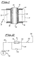
- the device (8) of the present invention comprises essentially a metal nucleus (10) inserted in a tubular body (12) made of insulating material, e.g. plastic, and bounded at its opposite ends by flanges (14,16).
- a winding (13) consisting of copper wires positioned stably by the flanges (14,16). Said winding (13) materializes an inductance connected to the winding of the motor and to a pair of switches and/or remote controlled switches as specified below.
- the winding or inductance (13) is preferably immersed in and cooled by the operating fluid of the motor which, in FIG. 1, is shown schematically in broken lines as a rectangle (11).
- the winding or inductance (13) can be provided by winding around the tubular body (12) the same wire coming from the motor winding.
- the metal nucleus (10) is stably positioned in the tubular body (12) by Seger cones (15) or equivalent means and traversed by a longitudinal passage (17) which reduces in this manner the total weight of the device (8).
- the device (8) provided in accordance with the present invention as described above is capable of eliminating or reducing considerably the known current peaks during starting of an asynchronous motor for control of hydraulic-traction elevators because it holds substantially always constant the supply voltage of the motor on the basis of known physical laws (Faraday-Newman-Leinz).
- the device (8) of the present invention causes an initial drop in voltage and hence in current by inductance instead of resistances.
- This voltage drop in the starting phase of the motor (18) can have a preset value in relation to the structural conformation of the winding (13).
- FIG. 2 shows by way of example an electrical diagram of a single-phase asynchronous motor (18) for control of hydraulic elevators including the device of FIG. 1. It is clear that if the motor (18) were the 3-phase type the electrical diagram would include three devices (8), i.e. one for each phase.
- the device (8) of the present invention is connected by a first wire (20) to the winding (21) of the motor (18) and by another wire (22) to a switch and/or remote controlled switch (23). The latter is connected in turn to the electric power line (24).
- Another wire (25) connected to another switch (26) by-passes the device (8) and connects to the first wire (20) and to the second wire (22) respectively.
- the function of the device (8) in activation of the motor (18) is as follows. Starting of the motor (18) is achieved by closing the switch (23) and holding open the switch (26). In this position of the switches (23,26) the current coming from the power supply line (24) passes from the wire (22) to the device (8), is 'filtered' by said device (8), passes from the wire (22) to the device (8), is 'filtered' by said device (8) and then sent over the wire (20) to the winding (21) of the motor (18) which begins its operational cycle reaching its nominal value.
- the switch (26) Upon achievement of the operational cycle of the motor (18) the switch (26) is closed and the current can also by-pass the device (8) because the voltage now required for powering said motor (18) remains substantially constant, i.e. the conditions in which the undesired current peaks occur no longer exist.
- the device (8) of the present invention can be defined a 'variable filter-reducer of current'.
Landscapes
- Engineering & Computer Science (AREA)
- Power Engineering (AREA)
- Motor And Converter Starters (AREA)
- Control Of Ac Motors In General (AREA)
- Control Of Motors That Do Not Use Commutators (AREA)
- Control Of Direct Current Motors (AREA)
- Control Of Electric Motors In General (AREA)
Claims (6)
- Dispositif pour réduire des pointes de courant lors du démarrage d'un moteur asynchrone (18) comportant des enroulements (21) pour la commande d'un élévateur hydraulique qui lui est associé, ledit dispositif comprenant un inducteur constitué par un enroulement (13) de fil métallique en cuivre sur un corps tubulaire (12) en une matière isolante et dans lequel est inséré un noyau métallique (10), ledit enroulement (13) de l'inducteur étant relié à chaque enroulement (21) du moteur et à un réseau d'alimentation en courant électrique (24), caractérisé en ce que l'enroulement (13) de l'inducteur est plongé dans et refroidi par un fluide (11) travaillant dans le moteur (18) et est réalisé en enroulant, autour dudit corps tubulaire (12), le même fil métallique (20) que celui provenant de l'enroulement (21) du moteur (18).
- Dispositif selon la revendication 1, caractérisé en ce que le corps tubulaire (12) est délimité, à ses extrémités opposées, par des brides (14, 16) qui maintiennent l'enroulement (13) en position stable.
- Dispositif selon l'une quelconque des revendications précédentes, caractérisé en ce que le noyau métallique (10) est traversé en direction longitudinale par un passage (17).
- Dispositif selon l'une quelconque des revendications précédentes, caractérisé en ce que la position du noyau métallique (10) est stabilisée dans le corps tubulaire (12) à l'aide de cônes de Seger (15).
- Dispositif selon l'une quelconque des revendications précédentes, caractérisé en ce que l'enroulement (13) est relié à l'enroulement (21) du moteur par un premier fil métallique (20) et au réseau d'alimentation en courant électrique (24) par un second fil métallique (22), lesdits premier et second fils métalliques (20, 22) étant également reliés directement l'un à l'autre à l'aide d'un autre fil métallique (25) muni d'un commutateur (26).
- Utilisation du dispositif selon l'une quelconque des revendications précédentes, relié à chaque phase d'un moteur asynchrone (18) pour la commande d'élévateurs hydrauliques.
Applications Claiming Priority (2)
| Application Number | Priority Date | Filing Date | Title |
|---|---|---|---|
| ITMI910746A IT1245557B (it) | 1991-03-20 | 1991-03-20 | Dispositivo atto a ridurre i "picchi" di corrente nell'avviamento di un motore elettrico asincrono per il comando di ascensori di tipo oleodinamico |
| ITMI910746 | 1991-03-20 |
Publications (2)
| Publication Number | Publication Date |
|---|---|
| EP0504610A1 EP0504610A1 (fr) | 1992-09-23 |
| EP0504610B1 true EP0504610B1 (fr) | 1997-05-14 |
Family
ID=11359140
Family Applications (1)
| Application Number | Title | Priority Date | Filing Date |
|---|---|---|---|
| EP92102901A Expired - Lifetime EP0504610B1 (fr) | 1991-03-20 | 1992-02-21 | Dispositif pour réduire les pointes de courant pendant le démarrage d'un moteur asynchrone |
Country Status (6)
| Country | Link |
|---|---|
| EP (1) | EP0504610B1 (fr) |
| AT (1) | ATE153195T1 (fr) |
| DE (1) | DE69219653T2 (fr) |
| ES (1) | ES2100968T3 (fr) |
| GR (1) | GR3023478T3 (fr) |
| IT (1) | IT1245557B (fr) |
Families Citing this family (1)
| Publication number | Priority date | Publication date | Assignee | Title |
|---|---|---|---|---|
| DE29605381U1 (de) * | 1996-03-22 | 1996-06-20 | Siemens AG, 80333 München | Drosselspule für einen Zwischenkreis-Kurzschließer |
Family Cites Families (4)
| Publication number | Priority date | Publication date | Assignee | Title |
|---|---|---|---|---|
| US2913640A (en) * | 1957-03-20 | 1959-11-17 | Gen Dynamics Corp | Electromagnetic coil assembly |
| CH558073A (de) * | 1972-03-17 | 1975-01-15 | Siemens Ag | Drosselspule. |
| GB2157087A (en) * | 1984-03-13 | 1985-10-16 | Weyrad | Improvements relating to linearity coils |
| DE3642724A1 (de) * | 1986-12-13 | 1988-06-23 | Grundfos Int | Elektromotor mit einem frequenzumrichter zur steuerung der motorbetriebsgroessen |
-
1991
- 1991-03-20 IT ITMI910746A patent/IT1245557B/it active IP Right Grant
-
1992
- 1992-02-21 AT AT92102901T patent/ATE153195T1/de not_active IP Right Cessation
- 1992-02-21 DE DE69219653T patent/DE69219653T2/de not_active Expired - Fee Related
- 1992-02-21 EP EP92102901A patent/EP0504610B1/fr not_active Expired - Lifetime
- 1992-02-21 ES ES92102901T patent/ES2100968T3/es not_active Expired - Lifetime
-
1997
- 1997-05-19 GR GR970401127T patent/GR3023478T3/el unknown
Also Published As
| Publication number | Publication date |
|---|---|
| EP0504610A1 (fr) | 1992-09-23 |
| ES2100968T3 (es) | 1997-07-01 |
| IT1245557B (it) | 1994-09-29 |
| ITMI910746A1 (it) | 1992-09-20 |
| ITMI910746A0 (it) | 1991-03-20 |
| DE69219653T2 (de) | 1997-09-04 |
| DE69219653D1 (de) | 1997-06-19 |
| GR3023478T3 (en) | 1997-08-29 |
| ATE153195T1 (de) | 1997-05-15 |
Similar Documents
| Publication | Publication Date | Title |
|---|---|---|
| EP0504610B1 (fr) | Dispositif pour réduire les pointes de courant pendant le démarrage d'un moteur asynchrone | |
| US6208111B1 (en) | Motor starter arrangement with soft start electronic control | |
| US4380724A (en) | Shunt field control apparatus and method | |
| EP0499989A2 (fr) | Procédé de réduction du courant de démarrage d'un moteur à cage d'écureuil et moteur à cage d'écureuil conçu pour la mise en oeuvre du procédé | |
| EP1228942A3 (fr) | Systèmes de direction assistée électrique | |
| US5334919A (en) | Motor control system having improved dynamic braking | |
| US3130328A (en) | Safety device for dual voltage circuits | |
| US1315996A (en) | Control system | |
| US911013A (en) | Motor-control system. | |
| GB197653A (en) | Improvements in moving platforms | |
| US1847081A (en) | Control system | |
| RU2025813C1 (ru) | Быстродействующий короткозамыкатель | |
| SU765959A1 (ru) | Устройство дл управлени электродвигателем посто нного тока | |
| JP2613543B2 (ja) | 低圧進相コンデンサ付可搬式分電盤 | |
| JPH05114521A (ja) | 電車搭載半導体電力変換器用の直流リアクトル | |
| US1549709A (en) | Load-limiting device for auto substations | |
| US1287647A (en) | Electrical protective device. | |
| SU1684899A2 (ru) | Электропривод | |
| US940550A (en) | Apparatus for starting electric motors. | |
| SU1209582A1 (ru) | Устройство дл управлени электроприводом механизма крана | |
| DE3410600A1 (de) | Schutzanlage: elektromotoren, kabelschutz, schutz gegen elektrische feuer | |
| US1097428A (en) | Controller for electric motors. | |
| US1237226A (en) | Induction-motor system. | |
| US819738A (en) | Electric-motor-control system. | |
| Krause | Starters and regulators for electric motors and generators: theory, construction, and connection |
Legal Events
| Date | Code | Title | Description |
|---|---|---|---|
| PUAI | Public reference made under article 153(3) epc to a published international application that has entered the european phase |
Free format text: ORIGINAL CODE: 0009012 |
|
| AK | Designated contracting states |
Kind code of ref document: A1 Designated state(s): AT BE CH DE DK ES FR GB GR LI LU NL PT SE |
|
| DX | Miscellaneous (deleted) | ||
| 17P | Request for examination filed |
Effective date: 19930302 |
|
| 17Q | First examination report despatched |
Effective date: 19941103 |
|
| GRAG | Despatch of communication of intention to grant |
Free format text: ORIGINAL CODE: EPIDOS AGRA |
|
| GRAH | Despatch of communication of intention to grant a patent |
Free format text: ORIGINAL CODE: EPIDOS IGRA |
|
| GRAH | Despatch of communication of intention to grant a patent |
Free format text: ORIGINAL CODE: EPIDOS IGRA |
|
| GRAA | (expected) grant |
Free format text: ORIGINAL CODE: 0009210 |
|
| AK | Designated contracting states |
Kind code of ref document: B1 Designated state(s): AT BE CH DE DK ES FR GB GR LI LU NL PT SE |
|
| PG25 | Lapsed in a contracting state [announced via postgrant information from national office to epo] |
Ref country code: DK Effective date: 19970514 |
|
| REF | Corresponds to: |
Ref document number: 153195 Country of ref document: AT Date of ref document: 19970515 Kind code of ref document: T |
|
| REG | Reference to a national code |
Ref country code: CH Ref legal event code: NV Representative=s name: TROESCH SCHEIDEGGER WERNER AG Ref country code: CH Ref legal event code: EP |
|
| REF | Corresponds to: |
Ref document number: 69219653 Country of ref document: DE Date of ref document: 19970619 |
|
| REG | Reference to a national code |
Ref country code: ES Ref legal event code: FG2A Ref document number: 2100968 Country of ref document: ES Kind code of ref document: T3 |
|
| ET | Fr: translation filed | ||
| REG | Reference to a national code |
Ref country code: GR Ref legal event code: FG4A Free format text: 3023478 |
|
| PG25 | Lapsed in a contracting state [announced via postgrant information from national office to epo] |
Ref country code: LU Free format text: LAPSE BECAUSE OF NON-PAYMENT OF DUE FEES Effective date: 19980221 |
|
| PLBE | No opposition filed within time limit |
Free format text: ORIGINAL CODE: 0009261 |
|
| STAA | Information on the status of an ep patent application or granted ep patent |
Free format text: STATUS: NO OPPOSITION FILED WITHIN TIME LIMIT |
|
| 26N | No opposition filed | ||
| REG | Reference to a national code |
Ref country code: GB Ref legal event code: IF02 |
|
| PGFP | Annual fee paid to national office [announced via postgrant information from national office to epo] |
Ref country code: GB Payment date: 20040109 Year of fee payment: 13 |
|
| PGFP | Annual fee paid to national office [announced via postgrant information from national office to epo] |
Ref country code: BE Payment date: 20040112 Year of fee payment: 13 |
|
| PGFP | Annual fee paid to national office [announced via postgrant information from national office to epo] |
Ref country code: FR Payment date: 20040123 Year of fee payment: 13 |
|
| PGFP | Annual fee paid to national office [announced via postgrant information from national office to epo] |
Ref country code: SE Payment date: 20040130 Year of fee payment: 13 |
|
| PGFP | Annual fee paid to national office [announced via postgrant information from national office to epo] |
Ref country code: ES Payment date: 20040224 Year of fee payment: 13 |
|
| PGFP | Annual fee paid to national office [announced via postgrant information from national office to epo] |
Ref country code: AT Payment date: 20040226 Year of fee payment: 13 |
|
| PGFP | Annual fee paid to national office [announced via postgrant information from national office to epo] |
Ref country code: PT Payment date: 20040227 Year of fee payment: 13 Ref country code: NL Payment date: 20040227 Year of fee payment: 13 Ref country code: GR Payment date: 20040227 Year of fee payment: 13 |
|
| PGFP | Annual fee paid to national office [announced via postgrant information from national office to epo] |
Ref country code: CH Payment date: 20040427 Year of fee payment: 13 |
|
| PGFP | Annual fee paid to national office [announced via postgrant information from national office to epo] |
Ref country code: DE Payment date: 20040430 Year of fee payment: 13 |
|
| PG25 | Lapsed in a contracting state [announced via postgrant information from national office to epo] |
Ref country code: GB Free format text: LAPSE BECAUSE OF NON-PAYMENT OF DUE FEES Effective date: 20050221 Ref country code: AT Free format text: LAPSE BECAUSE OF NON-PAYMENT OF DUE FEES Effective date: 20050221 |
|
| PG25 | Lapsed in a contracting state [announced via postgrant information from national office to epo] |
Ref country code: SE Free format text: LAPSE BECAUSE OF NON-PAYMENT OF DUE FEES Effective date: 20050222 Ref country code: ES Free format text: LAPSE BECAUSE OF NON-PAYMENT OF DUE FEES Effective date: 20050222 |
|
| PG25 | Lapsed in a contracting state [announced via postgrant information from national office to epo] |
Ref country code: LI Free format text: LAPSE BECAUSE OF NON-PAYMENT OF DUE FEES Effective date: 20050228 Ref country code: CH Free format text: LAPSE BECAUSE OF NON-PAYMENT OF DUE FEES Effective date: 20050228 Ref country code: BE Free format text: LAPSE BECAUSE OF NON-PAYMENT OF DUE FEES Effective date: 20050228 |
|
| PG25 | Lapsed in a contracting state [announced via postgrant information from national office to epo] |
Ref country code: PT Free format text: LAPSE BECAUSE OF NON-PAYMENT OF DUE FEES Effective date: 20050822 |
|
| BERE | Be: lapsed |
Owner name: *GMV MARTINI S.P.A. Effective date: 20050228 |
|
| PG25 | Lapsed in a contracting state [announced via postgrant information from national office to epo] |
Ref country code: NL Free format text: LAPSE BECAUSE OF NON-PAYMENT OF DUE FEES Effective date: 20050901 Ref country code: DE Free format text: LAPSE BECAUSE OF NON-PAYMENT OF DUE FEES Effective date: 20050901 |
|
| PG25 | Lapsed in a contracting state [announced via postgrant information from national office to epo] |
Ref country code: GR Free format text: LAPSE BECAUSE OF NON-PAYMENT OF DUE FEES Effective date: 20050905 |
|
| EUG | Se: european patent has lapsed | ||
| GBPC | Gb: european patent ceased through non-payment of renewal fee |
Effective date: 20050219 |
|
| REG | Reference to a national code |
Ref country code: CH Ref legal event code: PL |
|
| PG25 | Lapsed in a contracting state [announced via postgrant information from national office to epo] |
Ref country code: FR Free format text: LAPSE BECAUSE OF NON-PAYMENT OF DUE FEES Effective date: 20051031 |
|
| REG | Reference to a national code |
Ref country code: PT Ref legal event code: MM4A Effective date: 20050822 |
|
| NLV4 | Nl: lapsed or anulled due to non-payment of the annual fee |
Effective date: 20050901 |
|
| REG | Reference to a national code |
Ref country code: FR Ref legal event code: ST Effective date: 20051031 |
|
| REG | Reference to a national code |
Ref country code: ES Ref legal event code: FD2A Effective date: 20050222 |
|
| BERE | Be: lapsed |
Owner name: *GMV MARTINI S.P.A. Effective date: 20050228 |