EP0504867B1 - Commande par ordinateur pour système de levage comportant au moins deux palans - Google Patents
Commande par ordinateur pour système de levage comportant au moins deux palans Download PDFInfo
- Publication number
- EP0504867B1 EP0504867B1 EP92104771A EP92104771A EP0504867B1 EP 0504867 B1 EP0504867 B1 EP 0504867B1 EP 92104771 A EP92104771 A EP 92104771A EP 92104771 A EP92104771 A EP 92104771A EP 0504867 B1 EP0504867 B1 EP 0504867B1
- Authority
- EP
- European Patent Office
- Prior art keywords
- hoists
- computer
- control computer
- channel
- hoisting system
- Prior art date
- Legal status (The legal status is an assumption and is not a legal conclusion. Google has not performed a legal analysis and makes no representation as to the accuracy of the status listed.)
- Expired - Lifetime
Links
- 230000033001 locomotion Effects 0.000 claims abstract description 19
- 238000012544 monitoring process Methods 0.000 claims abstract description 11
- 230000001360 synchronised effect Effects 0.000 claims abstract 2
- 238000000034 method Methods 0.000 claims description 9
- 230000009977 dual effect Effects 0.000 claims 1
- 238000001514 detection method Methods 0.000 abstract description 4
- 238000010276 construction Methods 0.000 description 7
- 239000000725 suspension Substances 0.000 description 6
- 230000015572 biosynthetic process Effects 0.000 description 3
- 230000000694 effects Effects 0.000 description 2
- 240000004752 Laburnum anagyroides Species 0.000 description 1
- 229910000831 Steel Inorganic materials 0.000 description 1
- XAGFODPZIPBFFR-UHFFFAOYSA-N aluminium Chemical compound [Al] XAGFODPZIPBFFR-UHFFFAOYSA-N 0.000 description 1
- 229910052782 aluminium Inorganic materials 0.000 description 1
- 238000012937 correction Methods 0.000 description 1
- 239000000835 fiber Substances 0.000 description 1
- 231100001261 hazardous Toxicity 0.000 description 1
- 230000007257 malfunction Effects 0.000 description 1
- 239000000203 mixture Substances 0.000 description 1
- 230000002265 prevention Effects 0.000 description 1
- 230000001681 protective effect Effects 0.000 description 1
- 239000010959 steel Substances 0.000 description 1
- 238000005303 weighing Methods 0.000 description 1
- 239000002023 wood Substances 0.000 description 1
Images


Classifications
-
- A—HUMAN NECESSITIES
- A63—SPORTS; GAMES; AMUSEMENTS
- A63J—DEVICES FOR THEATRES, CIRCUSES, OR THE LIKE; CONJURING APPLIANCES OR THE LIKE
- A63J1/00—Stage arrangements
- A63J1/02—Scenery; Curtains; Other decorations; Means for moving same
- A63J1/028—Means for moving hanging scenery
Definitions
- the invention relates to a computer-controlled hoist system with at least two hoists, which is particularly suitable for stages and multi-purpose halls.
- hoist systems are mainly used in studios, stages, discotheques, in shows and other events.
- Lifting hoists are to be understood as supporting means that can move loads.
- Hoists consist of a drive and the associated supporting structure, e.g. Chain hoists and wire rope hoists.
- the hoist system is intended, for example, to raise an "artificial" lace-up floor, described below, and the PA and lighting systems attached to it.
- the "artificial" lace-up method is made possible by the fact that several hoists are grouped together.
- each drive is assigned an autonomous computer. All drive computers are connected to a common bus together with a common switching computer. An operating computer is assigned to an operating terminal and is connected to the switching computer. Position data of their respective drive are fed to the drive computers via actual value transmitters; depending on commands from the switching computer, they control and monitor their drive, including the calculation and regulation of speeds, and provide position data and error messages to the switching computer.
- the operating computer monitors and manages command buttons, switches and displays on the operator terminal, interprets group combinations of drives, stores data chains for specified movement sequences and transmits travel commands to the switching computer.
- the switching computer monitors the data traffic from and to the operator computer, as well as from and to the drives or drive computers, it keeps lists with actual values of all drives and permanent error states, continuously checks the data paths to all other computers and carries out the necessary switching measures in the event of an error.
- the drive computers continuously calculate the target position of your drive by evaluating direction, speed and group composition commands and initiate the necessary corrections in the event of deviations between the actual and target positions.
- the drives are switched off if deviations between the actual and target positions are found that exceed a specified maximum value.
- the drive computer carries out a safety check for the drives and itself, in particular tracking error and slack rope monitoring, as well as monitoring of pre-and emergency limit switches.
- the switching computer is connected to the operating computer via a serial interface and a serial reserve interface, as well as associated lines, and it automatically switches over to the reserve interface in the event of data traffic disruptions.
- the position data of the actual value transmitters are fed to the switching computer.
- grouping drives it checks the synchronism of the drives within the groups independently of the drive computers of the groups by comparing the position data.
- the control panel has one or more master switches that enable the group travel speed and direction to be set for group combinations of drives via the operating computer.
- Weight detection is not carried out in the prior art, which represents a security risk. If a weight is attached to the drives, which is greater than the maximum permissible load at the suspension point of the respective drive, there is a risk of the roof structure collapsing. A shift in weight within a group, for example due to slipping of the attached construction or due to failure of a hoist, can also lead to an impermissible load on the roof structure. If, for example, a truss construction is brought to a desired height by several drives at the same time, this also involves dangers.
- Under truss constructions are e.g. Understand wood, steel or aluminum truss constructions. By combining several trusses, an “artificial" lace is formed. On this "artificial" lacing floor e.g. Lighting and sound systems attached. If the weight of the attached load is too high, the truss construction can break, or there is a risk that the maximum load on the suspension points will be exceeded. Since there are no weight recording facilities at event venues, it is necessary to estimate the loads to be suspended in the roof structure, which is not a reproducible method on the one hand and leads to errors on the other.
- the usual computers are single-channel.
- a single-channel switching computer runs the risk that system errors that occur will not be recognized, since there is no comparison of the process data.
- the switching computer is equipped with the operator computer by means of a two-channel data line, but if the operator computer fails, the operator console can no longer be used. If the operating computer fails, no load could then be moved out of the danger area. This danger is further increased by the possibility of operating errors due to a very large number of control buttons - according to DE-A-32 33 468, about 300 buttons, 250 light-emitting diodes and 100 number display decades are necessary.
- the invention has for its object to provide a computer-controlled hoist system of the type mentioned, which meets the above-mentioned safety requirements and in particular avoids overloading the roof structure, the truss structure or individual hoists. This is to avoid endangering personnel, artists and the public. Furthermore, such a hoist system to relieve the personnel should be easy and clear to operate.
- the hoist system according to the invention is based on a multi-channel, in particular two-channel control computer, that is to say a control computer with two or more programmable logic controllers ("PLC”), which is connected to the hoist trains, the operator terminal and the operator computer via a coaxial ring network.
- PLC programmable logic controller
- the control system is designed redundantly; Further control of the system is guaranteed even if one channel fails.
- one channel is monitored by the other. If deviations between the channels are found that exceed a specified tolerance range, the system is shut down or other specified measures are initiated.
- the mutual monitoring of the two channels takes into account any time shifts that may occur in the parallel arithmetic operations by specifying a time interval within which there must be agreement.
- the operator computer is assigned to the operator terminal, but the operator terminal can be used independently of the operator computer. This is particularly necessary if individual hoists still have to be operated. In the case of group connections of the drives, however, the use of the operating computer is preferable. Accordingly, the hoist system according to the invention allows both individual trips and group switching of the respective drives.
- the respective position of the drives is communicated to the control computer via actual value transmitters, and likewise, preferably via strain gauges known per se, the respective load of the individual hoist trains. All the hoists in motion in a group are checked for synchronism, load and height position, all motors that are at a standstill are checked for standstill and load. When the individual trains move, the height position and load are checked.
- control computer preferably maintains lists with the maximum permissible loads of the suspension points, the exceeding of which stops the entire system and, if necessary, predetermined, safety-related measures are carried out, for example relieving the suspension points by returning to a starting position. Error messages are forwarded to the operator computer and displayed on it.
- the control computer also continuously checks the data traffic in the coaxial ring network and takes the specified, safety-related measures in the event of malfunctions, such as decommissioning the hoist trains or returning to a specified or starting position.
- the control computer monitors and manages the command buttons, switches and displays of the operator terminal, interprets group combinations of the individual hoists and stores data chains for specified movement sequences.
- the control computer releases the travel commands when it has checked all the processes.
- the hoist system has a permanently installed height measuring system which is used to compare the actual / setpoint of the Tax calculator is involved. During group journeys, the individual hoists are monitored for compliance with the permissible height deviation within the group in order not to destroy suspended truss constructions and to avoid weight shifts within a group of hoists and the resulting overloading.
- a weight detection by means of load measuring devices, preferably arranged on the individual drives, makes it possible to detect load shifts within a group and to stop the drives when the permissible tolerance is exceeded and, if necessary, to take further measures.
- a slack chain shutdown must be carried out on unloaded hoists so that dangers to people are avoided. If an unloaded hoist hits an obstacle, the hook block stops at this point and the chain continues to descend (slack chain formation).
- a slack chain shutdown on loaded hoists that are moved in a group can avoid the following problems. If the group consists of, for example, four drives and when hitting an obstacle if three hoists are relieved, there is a risk of overloading the fourth hoist. A punctiform load arises which contains a risk of overloading the drive, the traction means (break of the chain or the rope) or the permissible ceiling load at this suspension point can be exceeded. The same point overload can occur if three hoists of the group described above fail at the same time.
- All safety-relevant data is stored independent of the network, preferably in a battery-buffered RAM of the control computer.
- all the data that has occurred during operation is also stored within the control computer in order to be able to obtain and call up a reproducible event log and to document operating errors that occur.
- the drive is monitored for synchronism by the installed height measuring device, for example using an incremental encoder.
- the control computer calculates the data for the lead train and then compares it with the real measured data.
- further measures to increase security are possible.
- a preferred option is to record the position and weight multiple times. Both channels of the control computer compare the measured values with each other and initiate the safety-related measures in the event of deviations. If the position and the weight of at least some of the hoists are recorded twice, each is expediently of the two parallel data records from one channel each.
- group formation rules can be defined, e.g. prevent loaded drives from being deleted from a group before they have been relieved, and to prevent double assignment in two different groups.
- the control enables opposite movements, and if different distances are specified, the control computer calculates the necessary speed of all trains so that all trains arrive at their destination at the same time. Staggered movements, movements in wave form, rocking movements and movements in tilting sequences are also possible.
- a logon procedure can be installed on the operating computer, which must first be carried out before the system releases the system.
- All data that is saved can be it security-related or event-related data, can be saved on disk as well as on disk. This data can also be printed out using a log printer.
- the operating computer can be divided into further sub-control panels, which can then be brought into areas in which complicated movements are carried out. Only drives that have previously been released by the operator computer can be selected on the sub-control panels.
- the operating computer coordinates the various sub-control panels and outputs them Data from all sub-control panels to the control computer. However, a version is also possible in which all control panels communicate directly with the control computer.
- the hoists can either be installed stationary or movable.
- control can also be used for all other drive types, e.g. hydraulic drives that lift platforms and platforms.
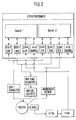
- the two-channel control computer (1) has access to the operator terminal via the coaxial ring network (2) (5), the operating computer (6) and the individual drives (4a, 4b, 4c, 4d, ... 4n).
- Fig. 2 shows the two-channel structure of the control computer, in which each of the channels (1 and 2) has independent access to the data and to the ring network. All data from the drives to the control computer are read from both channels of the control computer, and a comparison is made between the channels. This measure primarily prevents multiple errors and prevents misinformation from disrupting the operational process. If the comparison leads to different values, the system is shut down or other, predetermined measures are initiated.
- the clock of the system is specified by a defined time window, which also regulates the timing of the channels.
- the weight is recorded, for example, via strain gauges (DMS), which transmit the recorded values to the channels of the control computer via load-frequency converters (LSW) and frequency-voltage converters (FSW).
- DMS strain gauges
- LSW load-frequency converters
- FSW frequency-voltage converters
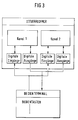
- FIG. 5 shows the coaxial ring network with a main loop and a sub loop. For example, If the main loop to the channel (1) is disrupted, the sub loop is immediately switched to.
- a possible application example is the positioning of lighting and public address systems above the Stage at music events.
- the "artificial" lacing floor is moved to working height with the hoists.
- music boxes are moved onto the stage, which can now be attached to any point on the "artificial” lacing floor, if the maximum permissible load in the suspension points is not exceeded.
- hoist control Another application of the hoist control is the "tracking system” described below, which has hoists that move a frame in the vertical direction. At the same time, this tracking system, e.g. B. on a rail system, movable in the horizontal direction.
- this tracking system e.g. B. on a rail system, movable in the horizontal direction.
- the overall system can be implemented as shown in FIG. 6.
- a traverse structure 10 is moved in height.
- a rail system 11 is mounted on the truss construction 10, on which a frame 12 is moved.
- a drive is also provided for the horizontal movement of the frame 12.
- All of these drives can be moved using the control described at the beginning. Single and group trips are possible.
- the control levers are located on the central control panel or a secondary panel, which enables all functions of the tracking system.
- the driving levers increase the speed proportionally to the lever design. The speed is infinitely adjustable. The maximum speed of the individual drives is preferably limited via the control. With the help of the drive levers motion sequences can be followed in the teach-in process and saved afterwards. Individual motion sequences, also called “cue's", can then be linked to form more complex motion sequences. Movements assembled in this way can then be called up again automatically.
- the driving data can also be entered using the keyboard.
- monitors can be mounted on the control panel.
- a variant is, for example, that the current driving data, the start and end positions are displayed on a monitor of the control panel.
- a floor plan of the local conditions is shown on a second monitor and the movements of the drives are shown to scale. It can be conveniently switched between different views (side view, top view, etc.).
- Predefined safety areas can prevent hazardous areas from being approached.
- the user interface on the monitor naturally offers further display options, which are not listed here.
- the tracking system contains in particular is the possibility of moving a scanner head of a laser system via the movable frame.
- a fiber optic cable makes it possible for the scanner head of the laser to move in space, thereby producing laser effects in three-dimensional space.
- a combination of the tracking system with the laser opens up new, varied show and lighting effects in an unprecedented way.
Landscapes
- Control And Safety Of Cranes (AREA)
- Selective Calling Equipment (AREA)
Claims (6)
- Système de levage commandé par ordinateur, en particulier pour des scènes et des salles polyvalentes, comportant- au moins deux palans (4a, 4b, ...) pouvant être commandés indépendamment,- un ordinateur de commande (1) qui est destiné à surveiller le système et à commander les différents. palans (4a, 4b, ...) et effectue une comparaison entre valeur instantanée et valeur de consigne en déterminant la position et l'état de déplacement des différents palans (4a, 4b, ...) et en contrôlant le relâchement des chaînes et le synchronisme de palans (4a, 4b, ...) groupés,- un terminal d'exploitation (5),- un ordinateur d'exploitation (6) destiné à gérer le terminal d'exploitation (5) et à transmettre des ordres de déplacement à l'ordinateur de commande (1),- un réseau (2), destiné à relier l'ordinateur de commande (1), l'ordinateur d'exploitation (6), le terminal d'exploitation (5) et les différents palans (4a, 4b, ...),caractérisé en ce que l'ordinateur de commande (1) et l'ordinateur d'exploitation (6)- sont reliés entre eux par un réseau en boucle comportant une boucle principale et une boucle secondaire, et- l'ordinateur de commande (1) possède une structure à plusieurs canaux avec au moins deux canaux (1a, 1b) et effectue la comparaison entre valeur instantanée et valeur de consigne indépendamment dans chaque canal (1a, 1b) ainsi qu'un contrôle mutuel de chaque canal (1a, 1b) respectivement par l'autre (1b, 1a) et s'il constate des écarts importants du point de vue de la sécurité, arrête le système de levage par l'intermédiaire de circuits de coupure comportant au moins deux canaux, au moins une détermination du poids étant en outre prévue dans le cadre de la comparaison entre valeur instantanée et valeur de consigne.
- Système de levage selon la revendication 1, caractérisé en ce que l'ordinateur de commande (1) possède une structure à deux canaux.
- Système de levage selon l'une des revendications 1 ou 2, caractérisé en ce qu'il est prévu une détermination du poids total et du poids respectif supporté par les différents palans (4a, 4b, ...), de préférence par l'intermédiaire de jauges extensométriques.
- Système de levage selon la revendication 3, caractérisé en ce qu'il est prévu de plus une détermination du poids de palans (4a, 4b, ...) groupés.
- Système de levage selon l'une des revendications 1 à 4, caractérisé en ce que la comparaison entre valeur instantanée et valeur de consigne s'effectue à l'aide d'une représentation de processus mémorisée dans l'ordinateur de commande (1).
- Système de levage selon la revendication 5, caractérisé en ce que la représentation de processus présente une plage de tolérances dont le dépassement par valeur négative ou positive produit l'arrêt du système de levage.
Applications Claiming Priority (2)
| Application Number | Priority Date | Filing Date | Title |
|---|---|---|---|
| DE4108969A DE4108969A1 (de) | 1991-03-19 | 1991-03-19 | Rechnergesteuertes hubzugsystem mit wenigstens zwei hubzuegen |
| DE4108969 | 1991-03-19 |
Publications (2)
| Publication Number | Publication Date |
|---|---|
| EP0504867A1 EP0504867A1 (fr) | 1992-09-23 |
| EP0504867B1 true EP0504867B1 (fr) | 1996-12-27 |
Family
ID=6427684
Family Applications (1)
| Application Number | Title | Priority Date | Filing Date |
|---|---|---|---|
| EP92104771A Expired - Lifetime EP0504867B1 (fr) | 1991-03-19 | 1992-03-19 | Commande par ordinateur pour système de levage comportant au moins deux palans |
Country Status (3)
| Country | Link |
|---|---|
| EP (1) | EP0504867B1 (fr) |
| AT (1) | ATE146687T1 (fr) |
| DE (2) | DE4108969A1 (fr) |
Cited By (2)
| Publication number | Priority date | Publication date | Assignee | Title |
|---|---|---|---|---|
| US7775506B2 (en) | 2006-04-28 | 2010-08-17 | Electronic Theatre Controls, Inc. | Lift assembly, system, and method |
| US8317159B2 (en) | 2007-11-08 | 2012-11-27 | Electronic Theatre Controls, Inc. | Lift assembly systems and methods |
Families Citing this family (13)
| Publication number | Priority date | Publication date | Assignee | Title |
|---|---|---|---|---|
| DE4440064C2 (de) * | 1994-11-10 | 2000-09-21 | Hella Kg Hueck & Co | Schaltungsanordnung zur Ansteuerung elektrischer Lasten |
| DE19612423A1 (de) * | 1996-03-28 | 1997-10-02 | Siemens Ag | Steuer- und Sicherheitssystem für Krananlagen |
| DE10041035A1 (de) | 2000-08-22 | 2002-03-07 | Heinrich Bader | Vorrichtung und Verfahren zum Mechanisieren von Seil- und Prospektzügen, insbesondere im Bühnenbereich |
| DE10146521B4 (de) * | 2001-09-21 | 2006-08-17 | Rainer Puls | Steuerungssystem für Seilwinden und andere Maschinen |
| DE10209482A1 (de) * | 2002-03-05 | 2003-10-02 | Wittenstein Ag | Verfahren zum Gestalten eines Bühnenbildes |
| EP1597637B1 (fr) | 2003-02-28 | 2008-06-11 | Gottwald Port Technology GmbH | Procede et dispositif pour deconnecter de maniere sure des commandes electriques |
| WO2007010290A2 (fr) * | 2005-07-22 | 2007-01-25 | Spatial Systems Limited | Assemblage de surface |
| DE102005050699B4 (de) * | 2005-10-18 | 2016-01-07 | Terex Cranes Germany Gmbh | Verfahren zum Betrieb eines Kranes mit Mehrfachseiltrieb |
| ATE540343T1 (de) | 2009-10-23 | 2012-01-15 | Sick Ag | Sicherheitssteuerung |
| EP2910514B1 (fr) | 2009-11-18 | 2016-10-19 | Electronic Theatre Controls, Inc. | Systèmes et procédés d'assemblage d'ascenseurs |
| AT509781B1 (de) * | 2010-04-27 | 2013-02-15 | Waagner Biro Austria Stage Systems Ag | Verfahren und vorrichtung zum ausgleichen von kräften bzw. momenten in einer punktzuganlage oder prospektzuganlage |
| US10183850B2 (en) | 2012-12-21 | 2019-01-22 | Electronic Theatre Controls, Inc. | Compact hoist system |
| JP6066376B1 (ja) * | 2015-08-10 | 2017-01-25 | 株式会社Isa | 舞台演出システム及び舞台演出方法 |
Family Cites Families (7)
| Publication number | Priority date | Publication date | Assignee | Title |
|---|---|---|---|---|
| US3986703A (en) * | 1973-06-21 | 1976-10-19 | Evershed Power-Optics Limited | Movement of scenery in theaters and studios |
| DE3103708A1 (de) * | 1981-02-04 | 1982-08-12 | Bayerische Bühnenbau GmbH, 8480 Weiden | Einrichtung fuer den betrieb von theaterzuegen einer theaterbuehne |
| DE3233468A1 (de) * | 1982-09-09 | 1984-03-15 | Trepel Ag, 6200 Wiesbaden | Steueranlage fuer die schnuerbodenmaschinerie von buehnen |
| DE3303607A1 (de) * | 1983-02-03 | 1983-07-14 | Dieter 5800 Hagen Müller | Gleichlauf-regelung fuer hebezeugelemente mit gemeinsamer last |
| DE3420596C2 (de) * | 1984-06-01 | 1986-10-02 | Dr.-Ing. Ludwig Pietzsch Gmbh & Co, 7505 Ettlingen | Überwachungs- und Steuersystem für Auslegerkrane |
| DE3714803A1 (de) * | 1987-05-04 | 1988-11-17 | Siemens Ag | Optische vorrichtung zum aufzeichnen und wiedergeben einer auf einer speicherplatte gespeicherten information |
| US4905848A (en) * | 1988-06-06 | 1990-03-06 | Skjonberg Knut B | Coordinated hoist controllers |
-
1991
- 1991-03-19 DE DE4108969A patent/DE4108969A1/de not_active Withdrawn
-
1992
- 1992-03-19 AT AT92104771T patent/ATE146687T1/de active
- 1992-03-19 EP EP92104771A patent/EP0504867B1/fr not_active Expired - Lifetime
- 1992-03-19 DE DE59207741T patent/DE59207741D1/de not_active Expired - Fee Related
Cited By (4)
| Publication number | Priority date | Publication date | Assignee | Title |
|---|---|---|---|---|
| US7775506B2 (en) | 2006-04-28 | 2010-08-17 | Electronic Theatre Controls, Inc. | Lift assembly, system, and method |
| US8317159B2 (en) | 2007-11-08 | 2012-11-27 | Electronic Theatre Controls, Inc. | Lift assembly systems and methods |
| US8613428B2 (en) | 2007-11-08 | 2013-12-24 | Electronic Theatre Controls, Inc. | Lift assembly systems and methods |
| US9309094B2 (en) | 2007-11-08 | 2016-04-12 | Electronic Theatre Controls, Inc. | Lift assembly systems and methods |
Also Published As
| Publication number | Publication date |
|---|---|
| DE59207741D1 (de) | 1997-02-06 |
| DE4108969A1 (de) | 1992-09-24 |
| ATE146687T1 (de) | 1997-01-15 |
| EP0504867A1 (fr) | 1992-09-23 |
Similar Documents
| Publication | Publication Date | Title |
|---|---|---|
| EP0504867B1 (fr) | Commande par ordinateur pour système de levage comportant au moins deux palans | |
| EP2022742B1 (fr) | Système d'ascenseur | |
| EP1894882B1 (fr) | Procédé de protection et de commande pour grue | |
| EP1401757A1 (fr) | Procede pour empecher une vitesse inacceptablement elevee du moyen de suspension de charge d'un ascenseur | |
| EP2719652B1 (fr) | Dispositif de transport de personnes au moyen d'une grue, et grue dotée d'un dispositif de transport de personnes | |
| EP0769469A1 (fr) | Dispositif de sécurité pour groupes d'ascenseur multi-mobiles | |
| DE102011053014A1 (de) | Steuerungsanordnung zum parallelen Betreiben von mindestens zwei Hebezeugen, insbesondere Kranen | |
| DE112016006975T5 (de) | Sicherheitssteuerungsvorrichtung und Sicherheitssteuerungsverfahren für einen Mehrfachkabinenaufzug | |
| EP3353108B1 (fr) | Dispositif de surveillance d'ascenseur | |
| WO2002018264A1 (fr) | Systeme de securite redondant d'un vehicule | |
| EP2160349B1 (fr) | Agencement, module et procédé pour le fonctionnement sûr d'une installation | |
| DE3233468A1 (de) | Steueranlage fuer die schnuerbodenmaschinerie von buehnen | |
| EP3368462B1 (fr) | Procédé pour faire fonctionner au moins deux appareils de levage en groupe, et ensemble comportant au moins deux appareils de levage | |
| DE112006000498T5 (de) | Aufzuganlage | |
| EP0747535A1 (fr) | Dispositif et procédé pour déplacer des bâtiments | |
| EP1427499B1 (fr) | Systeme de commande pour treuils de manoeuvre et autres machines | |
| DE19905020A1 (de) | Verfahren zur ständigen Überwachung der ordnungsgemäßen Betriebsfunktion eines Kranes | |
| EP1985574B1 (fr) | Agencement de commande destiné au fonctionnement parallèle d'au moins deux palans à chaînes | |
| EP1024107A2 (fr) | Grue, en particulier pour transporter des masses fondues | |
| EP4574737A1 (fr) | Dispositif de barre de levage | |
| DE10230469B4 (de) | Vorrichtung zum Überwachen der Zulässigkeit der augenblicklichen Belastung einer Hubeinrichtung | |
| EP1151953A1 (fr) | Dispositif d'évacuation des passagers d'un ascenseur | |
| DE102023109701A1 (de) | Verfahren, System und Computerprogrammprodukt zum Bewegen einer Last mittels einer Mehrzahl von Kranen | |
| DE3233788A1 (de) | Steuerungsanlage fuer eine buehnenmaschinerie | |
| DE9212698U1 (de) | Anordnung zur Drehzahlüberwachung bei einem Hubwerk mit zwei Seiltrommeln |
Legal Events
| Date | Code | Title | Description |
|---|---|---|---|
| PUAI | Public reference made under article 153(3) epc to a published international application that has entered the european phase |
Free format text: ORIGINAL CODE: 0009012 |
|
| AK | Designated contracting states |
Kind code of ref document: A1 Designated state(s): AT BE CH DE DK ES FR GB IT LI NL SE |
|
| 17P | Request for examination filed |
Effective date: 19930323 |
|
| 17Q | First examination report despatched |
Effective date: 19930804 |
|
| RAP1 | Party data changed (applicant data changed or rights of an application transferred) |
Owner name: FRUEH, INGOLF |
|
| GRAG | Despatch of communication of intention to grant |
Free format text: ORIGINAL CODE: EPIDOS AGRA |
|
| GRAH | Despatch of communication of intention to grant a patent |
Free format text: ORIGINAL CODE: EPIDOS IGRA |
|
| GRAH | Despatch of communication of intention to grant a patent |
Free format text: ORIGINAL CODE: EPIDOS IGRA |
|
| GRAA | (expected) grant |
Free format text: ORIGINAL CODE: 0009210 |
|
| AK | Designated contracting states |
Kind code of ref document: B1 Designated state(s): AT BE CH DE DK ES FR GB IT LI NL SE |
|
| PG25 | Lapsed in a contracting state [announced via postgrant information from national office to epo] |
Ref country code: IT Free format text: LAPSE BECAUSE OF FAILURE TO SUBMIT A TRANSLATION OF THE DESCRIPTION OR TO PAY THE FEE WITHIN THE PRE;WARNING: LAPSES OF ITALIAN PATENTS WITH EFFECTIVE DATE BEFORE 2007 MAY HAVE OCCURRED AT ANY TIME BEFORE 2007. THE CORRECT EFFECTIVE DATE MAY BE DIFFERENT FROM THE ONE RECORDED.SCRIBED TIME-LIMIT Effective date: 19961227 Ref country code: NL Free format text: LAPSE BECAUSE OF FAILURE TO SUBMIT A TRANSLATION OF THE DESCRIPTION OR TO PAY THE FEE WITHIN THE PRESCRIBED TIME-LIMIT Effective date: 19961227 Ref country code: ES Free format text: THE PATENT HAS BEEN ANNULLED BY A DECISION OF A NATIONAL AUTHORITY Effective date: 19961227 Ref country code: DK Effective date: 19961227 |
|
| REF | Corresponds to: |
Ref document number: 146687 Country of ref document: AT Date of ref document: 19970115 Kind code of ref document: T |
|
| GBT | Gb: translation of ep patent filed (gb section 77(6)(a)/1977) |
Effective date: 19970102 |
|
| REF | Corresponds to: |
Ref document number: 59207741 Country of ref document: DE Date of ref document: 19970206 |
|
| PG25 | Lapsed in a contracting state [announced via postgrant information from national office to epo] |
Ref country code: SE Effective date: 19970327 |
|
| REG | Reference to a national code |
Ref country code: CH Ref legal event code: NV Representative=s name: RITSCHER & SEIFERT PATENTANWAELTE VSP |
|
| PG25 | Lapsed in a contracting state [announced via postgrant information from national office to epo] |
Ref country code: BE Effective date: 19970331 |
|
| ET | Fr: translation filed | ||
| NLV1 | Nl: lapsed or annulled due to failure to fulfill the requirements of art. 29p and 29m of the patents act | ||
| BERE | Be: lapsed |
Owner name: FRUH INGOLF Effective date: 19970331 |
|
| PLBE | No opposition filed within time limit |
Free format text: ORIGINAL CODE: 0009261 |
|
| STAA | Information on the status of an ep patent application or granted ep patent |
Free format text: STATUS: NO OPPOSITION FILED WITHIN TIME LIMIT |
|
| PG25 | Lapsed in a contracting state [announced via postgrant information from national office to epo] |
Ref country code: FR Free format text: LAPSE BECAUSE OF NON-PAYMENT OF DUE FEES Effective date: 19971128 |
|
| 26N | No opposition filed | ||
| REG | Reference to a national code |
Ref country code: FR Ref legal event code: ST |
|
| PGFP | Annual fee paid to national office [announced via postgrant information from national office to epo] |
Ref country code: GB Payment date: 19980403 Year of fee payment: 7 |
|
| PGFP | Annual fee paid to national office [announced via postgrant information from national office to epo] |
Ref country code: AT Payment date: 19980423 Year of fee payment: 7 |
|
| PGFP | Annual fee paid to national office [announced via postgrant information from national office to epo] |
Ref country code: CH Payment date: 19980424 Year of fee payment: 7 |
|
| PG25 | Lapsed in a contracting state [announced via postgrant information from national office to epo] |
Ref country code: AT Free format text: LAPSE BECAUSE OF NON-PAYMENT OF DUE FEES Effective date: 19990319 Ref country code: GB Free format text: LAPSE BECAUSE OF NON-PAYMENT OF DUE FEES Effective date: 19990319 |
|
| PG25 | Lapsed in a contracting state [announced via postgrant information from national office to epo] |
Ref country code: CH Free format text: LAPSE BECAUSE OF NON-PAYMENT OF DUE FEES Effective date: 19990331 Ref country code: LI Free format text: LAPSE BECAUSE OF NON-PAYMENT OF DUE FEES Effective date: 19990331 |
|
| GBPC | Gb: european patent ceased through non-payment of renewal fee |
Effective date: 19990319 |
|
| REG | Reference to a national code |
Ref country code: CH Ref legal event code: PL |
|
| PGFP | Annual fee paid to national office [announced via postgrant information from national office to epo] |
Ref country code: DE Payment date: 20010104 Year of fee payment: 9 |
|
| PG25 | Lapsed in a contracting state [announced via postgrant information from national office to epo] |
Ref country code: DE Free format text: LAPSE BECAUSE OF NON-PAYMENT OF DUE FEES Effective date: 20020101 |