EP0505178B1 - Werkzeug zum Erneuern von Profilen - Google Patents
Werkzeug zum Erneuern von Profilen Download PDFInfo
- Publication number
- EP0505178B1 EP0505178B1 EP19920302369 EP92302369A EP0505178B1 EP 0505178 B1 EP0505178 B1 EP 0505178B1 EP 19920302369 EP19920302369 EP 19920302369 EP 92302369 A EP92302369 A EP 92302369A EP 0505178 B1 EP0505178 B1 EP 0505178B1
- Authority
- EP
- European Patent Office
- Prior art keywords
- regrooving
- blade
- tyre
- probe
- soleplate
- Prior art date
- Legal status (The legal status is an assumption and is not a legal conclusion. Google has not performed a legal analysis and makes no representation as to the accuracy of the status listed.)
- Expired - Lifetime
Links
Images

Classifications
-
- B—PERFORMING OPERATIONS; TRANSPORTING
- B29—WORKING OF PLASTICS; WORKING OF SUBSTANCES IN A PLASTIC STATE IN GENERAL
- B29D—PRODUCING PARTICULAR ARTICLES FROM PLASTICS OR FROM SUBSTANCES IN A PLASTIC STATE
- B29D30/00—Producing pneumatic or solid tyres or parts thereof
- B29D30/06—Pneumatic tyres or parts thereof (e.g. produced by casting, moulding, compression moulding, injection moulding, centrifugal casting)
- B29D30/52—Unvulcanised treads, e.g. on used tyres; Retreading
- B29D30/68—Cutting profiles into the treads of tyres
Definitions
- This invention relates to a tyre regrooving tool and in particular to a tool wherein the position of the regrooving blade relative to the base of the grooves of the tread pattern of the tyre being regrooved is kept constant.
- Regrooving is carried out using a hand operated grooving tool usually having a heated cutting blade.
- a hand operated grooving tool usually having a heated cutting blade.
- the blade is set to protrude a certain distance below the baseplate or soleplate of the tool. This distance is determined by the person carrying out the regrooving operation based on measurement of the depth of tread pattern remaining on the tyre and the tyre manufacturer's recommendation regarding how deep the blade can cut into the rubber between the base of the tread pattern groove and the surface of the radially outermost breaker ply, which is normally called the underpattern rubber.
- the distance the blade is set to protrude is the sum of the pattern depth remaining and the depth to which the underpattern rubber can be removed.
- the setting of the blade cannot be specified exactly by the tyre manufacturer because it is dependent on the pattern depth remaining when the tyre user decides that the tyre will be regrooved. Also many tyres wear unevenly so that the pattern depth remaining is variable. Tyre manufacturers usually specify that the pattern depth remaining should be measured at several positions around the tyre and that the minimum pattern depth found should be used to set the cutter blade. The person regrooving the tyre must remember the minimum pattern depth found and add to this the tyre manufacturer's recommended regrooving depth and set the blade using a rule or feeler gauge. Thus the setting of the blade is very reliant on the skill and diligence of the person doing the regrooving.
- the blade may be set to protrude too far below the baseplate because of an error in measurement or misinterpretation of the tyre manufacturer's recommendation or the position of minimum pattern depth remaining having been missed when the tyre was measured.
- the regrooving tool baseplate follows the contours of the tread surface and the blade is fixed relative to the baseplate. This means that if the blade protrudes too far, when the tool is passing over a portion of the tread surface which is more worn away than adjacent areas the blade will cut away more of underpattern rubber and in some cases expose the wires of the outermost breaker ply.
- a tyre regrooving tool comprises a soleplate having a bottom surface for contacting a tyre tread surface, a depth sensing probe movable with respect to the soleplate and having a probe end projecting below the bottom surface of the soleplate for contacting the base of a tyre tread groove, a regrooving blade adjacent to the probe also movable with respect to the soleplate and projecting below the bottom surface of the soleplate and blade moving means between the probe and the blade so that movement of the probe causes similar movement of the regrooving blade and means are provided to keep the probe end in contact with the base of the tread groove when the bottom surface of the soleplate is in contact with the tread.
- a method of regrooving a tyre using the regrooving tool of the present invention whereby the depth sensing probe is inserted into a tyre tread groove to contact the base of the groove, the bottom surface of the soleplate is brought into contact with the tread surface and the tool is moved around the circumference of the tyre so that the regrooving blade cuts a new tread groove.
- the probe and the blade move in the same direction by an equal amount and the difference by which the blade projecting distance exceeds the probe projecting distance is equal to the recommended regrooving depth under the original tyre tread pattern.
- the blade is set at an angle of 0 to 5 degrees to the plane normal to the plane of the soleplate so that the blade is inclined backwards with respect to the direction of cutting.
- the probe end in contact with the tyre tread groove base is rounded or more preferably a roller or roller ball so that it cam move easily in the groove.
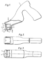
- the regrooving tool shown in Figure 1 comprises a stock 1 in which is mounted a blade holder carriage 2. Within the blade holder carriage 2 is slideably mounted a sliding member 3 to which is fixed a probe 4 and a blade holder 5.
- the probe 4 and blade holder 5 pass through a hole provided in a soleplate 7 which is fixed to the stock 1 for contacting the tyre tread surface.
- the probe 4 has an end 4a projecting below the bottom surface of the soleplate 7 for contacting the base of a tyre tread groove.
- the blade holder 5 holds a regrooving blade 6 which also projects below the bottom surface of the soleplate 7 for re-cutting the grooves of a tyre tread.
- the blade 6 is inclined backwards with respect to the direction movement of the tool which is in the direction shown by arrow M.
- the blade is inclined at 2 degrees so that the angle ⁇ , between the axis of the blade and the plane of the soleplate 7, is 88 degrees.
- the value of the angle ⁇ may be in the range of 85 to 90 degrees.
- the distance d by which the blade projecting distance exceeds the probe projecting distance corresponds to the depth below the base of the original groove that the new groove will be cut.
- the recommended value for the distance d for a particular tyre may be derived from the manufacturers regrooving literature by subtracting the recommended conventional blade setting.
- the distance d on the regrooving tool of the present invention may then be set by altering the probe projecting distance by changing the position of the probe 4 relative to the sliding member 3.
- Figure 6 shows how the probe 4 may be fixed to sliding member 3 by a clamp screw 9 to enable the probe to be moved and clamped in a new position relative to the sliding member 3.
- the regrooving depth may be conveniently set, as shown in figure 5, by pushing the probe 4 and the clamped assembly of the sliding member 3, blade holder 5 and blade 6 to the position where the probe end 4a is flush with the bottom surface of the soleplate 7.
- the blade may then be set by releasing the sliding assembly 3,5,6 from the probe by releasing the clamp screw 9, and moving the sliding assembly 3,5,6 so that the blade tip projects the required distance d from the bottom surface of the soleplate.
- the clamp screw 9 is then tightened and the regrooving tool is ready for use.
- the regrooving tool of the present invention is used in a similar manner to the conventional regrooving tool except that the probe end 4a is positioned in contact with the base of the original tread grooves slightly in front of the cutting blade. Sufficient pressure is applied to the stock 1 of the regrooving tool to force the sliding member 3 to slide into the blade holder carriage 2 against the action of the spring 8 until the bottom surface of the soleplate 7 comes in to contact with worn tyre surface. Regrooving is then carried out in the conventional way with the advantage that the blade depth with respect to the base of the groove remains fixed and independent of the projecting distance below the soleplate 7 so that the depth of the new cut is always correct and independent of the pattern depth remaining or variations thereof.
- the regrooving tool of the present invention provides a convenient tool which ensures correct and consistent regrooving regardless of variations in remaining pattern depth.
Landscapes
- Engineering & Computer Science (AREA)
- Mechanical Engineering (AREA)
- Tyre Moulding (AREA)
- Tires In General (AREA)
- Moulds For Moulding Plastics Or The Like (AREA)
Claims (13)
- Ein Reifenprofilerneuerungswerkzeug mit einer Grundplatte (7), die eine Bodenfläche zum Berühren einer Reifenlaufflächenoberfläche aufweist, einem Tiefenwahrnehmungsfühler (4), der bezüglich der Grundplatte (7) bewegbar ist und ein Fühlerende (4a) aufweist, das unterhalb der Bodenfläche der Grundplatte (7) zum Berühren des Grunds einer Reifenlaufflächennut vorsteht, einer Profilerneuerungsklinge (6) benachbart dem Fühler (4), die auch bezüglich der Grundplatte (7) bewegbar ist und unterhalb der Bodenfläche der Grundplatte (7) vorsteht, und Klingenbewegungsmitteln zwischen dem Fühler (4) und der Klinge (6), so daß eine Bewegung des Fühlers (4) eine gleichartige Bewegung der Profilerneuerungsklinge (6) verursacht und Mittel vorgesehen sind, um das Fühlerende (4a) in Kontakt mit dem Grund der Laufflächennut zu halten, wenn sich die Bodenfläche der Grundplatte (7) in Kontakt mit der Lauffläche befindet.
- Ein Reifenprofilerneuerungswerkzeug nach Anspruch 1,
dadurch gekennzeichnet,
daß das Klingenbewegungsmittel zwischen dem Fühler (4) und der Klinge (6) eine mechanische Verbindung umfaßt. - Ein Reifenprofilerneuerungswerkzeug nach Anspruch 1 oder 2,
dadurch gekennzeichnet,
daß die Bewegungen des Fühlers (4) und der Profilerneuerungsklinge (6) gleich groß und gleichgerichtet sind. - Ein Profilerneuerungswerkzeug nach Anspruch 1, 2 oder 3,
dadurch gekennzeichnet,
daß der Profilerneuerungsklingenvorstehabstand den Fühlerendevorstehabstand um einen Betrag (d) übersteigt, der gleich der empfohlenen Profilerneuerungstiefe unter dem ursprünglichen Reifenlaufflächenprofil ist. - Ein Profilerneuerungswerkzeug nach einem der Ansprüche 1 bis 4,
dadurch gekennzeichnet,
daß die Breite des Fühlerendes (4a) 5 mm oder weniger ist. - Ein Reifenprofilerneuerungswerkzeug nach einem der Ansprüche 1 bis 5,
dadurch gekennzeichnet,
daß die Ebene der Profilerneuerungsklinge (6) unter einem Winkel (α) von 85 bis 90 Grad bezüglich der Ebene der Grundplatte (7) geneigt ist, so daß die Spitze der Profilerneuerungsklinge bezüglich der Bewegungsrichtung des Profilerneuerungswerkzeugs nachläuft. - Ein Reifenprofilerneuerungswerkzeug nach einem der Ansprüche 1 bis 5,
dadurch gekennzeichnet,
daß die Ebene der Profilerneuerungsklinge unter einem Winkel (α) von 88 bis 90 Grad bezüglich der Ebene der Grundplatte (7) geneigt ist, so daß die Spitze der Profilerneuerungsklinge bezüglich der Bewegungsrichtung des Profilerneuerungswerkzeugs nachläuft. - Ein Profilerneuerungswerkzeug nach einem der Ansprüche 1 bis 7,
dadurch gekennzeichnet,
daß das Fühlerende (4a) gerundet ist, so daß es leicht entlang des Grunds einer Reifenlaufflächennut gleiten kann. - Ein Profilerneuerungswerkzeug nach einem der Ansprüche 1 bis 8,
dadurch gekennzeichnet,
daß das Fühlerende (4a) eine Rolle umfaßt. - Ein Profilerneuerungswerkzeug nach einem der Ansprüche 1 bis 9,
dadurch gekennzeichnet,
daß das Fühlerende (4a) eine Rollkugel umfaßt. - Ein Profilerneuerungswerkzeug nach einem der Ansprüche 1 bis 10,
dadurch gekennzeichnet,
daß das Mittel, um das Fühlerende (4a) in Kontakt mit dem Grund der Laufflächennut zu halten, wenn sich die Bodenfläche der Grundplatte (7) in Kontakt mit der Lauffläche befindet, ein Federmittel ist. - Ein Verfahren zur Profilerneuerung eines Reifens, welches das Profilerneuerungswerkzeug nach einem der Ansprüche 1 bis 11 verwendet,
dadurch gekennzeichnet,
daß der Tiefenwahrnehmungsfühler (4) in eine Reifenlaufflächennut hineingesetzt wird, um den Grund der Nut zu berühren, die Bodenfläche der Grundplatte (7) in Kontakt mit der Laufflächenoberfläche gebracht und das Werkzeug um den Umfang des Reifens herum bewegt wird, so daß die Profilerneuerungsklinge (6) eine neue Laufflächennut schneidet. - Ein Verfahren zur Profilerneuerung eines Reifens nach Anspruch 12,
dadurch gekennzeichnet,
daß der Fühler (4) und die Klinge (6) so eingestellt sind, daß der Vorstehabstand unterhalb der Bodenfläche der Grundplatte (7) der Klinge (6) denjenigen des Fühlers um einen Betrag (d) übersteigt, der gleich der empfohlenen Profilerneuerungstiefe unter dem ursprünglichen Profil ist.
Applications Claiming Priority (2)
| Application Number | Priority Date | Filing Date | Title |
|---|---|---|---|
| GB9106164 | 1991-03-22 | ||
| GB919106164A GB9106164D0 (en) | 1991-03-22 | 1991-03-22 | Tyre regrooving tool |
Publications (2)
| Publication Number | Publication Date |
|---|---|
| EP0505178A1 EP0505178A1 (de) | 1992-09-23 |
| EP0505178B1 true EP0505178B1 (de) | 1994-07-20 |
Family
ID=10692064
Family Applications (1)
| Application Number | Title | Priority Date | Filing Date |
|---|---|---|---|
| EP19920302369 Expired - Lifetime EP0505178B1 (de) | 1991-03-22 | 1992-03-19 | Werkzeug zum Erneuern von Profilen |
Country Status (3)
| Country | Link |
|---|---|
| EP (1) | EP0505178B1 (de) |
| DE (1) | DE69200245T2 (de) |
| GB (1) | GB9106164D0 (de) |
Families Citing this family (5)
| Publication number | Priority date | Publication date | Assignee | Title |
|---|---|---|---|---|
| FR2758768B1 (fr) * | 1997-01-24 | 1999-03-05 | Michelin & Cie | Bande de roulement a rainures recreusables |
| BRPI0621515A2 (pt) * | 2006-03-17 | 2012-09-11 | Pirelli Pneus Ltda | dispositivo de retalhamento e método para cortar entalhes parcialmente desgastados |
| JP2013129136A (ja) * | 2011-12-22 | 2013-07-04 | Yokohama Rubber Co Ltd:The | タイヤのグルービング装置 |
| US10894377B2 (en) | 2018-12-27 | 2021-01-19 | Moises Garcia | Tire regrooving tool and related methods |
| USD896602S1 (en) | 2019-02-13 | 2020-09-22 | Moises Garcia | Blade for a re-grooving tool |
Family Cites Families (3)
| Publication number | Priority date | Publication date | Assignee | Title |
|---|---|---|---|---|
| US2097811A (en) * | 1934-11-03 | 1937-11-02 | Foley Walter | Tire grooving tool |
| US2254974A (en) * | 1939-03-30 | 1941-09-02 | Triangle Tire & Battery Servic | Tire regrooving tool |
| US3626599A (en) * | 1969-03-05 | 1971-12-14 | Ashland Oil Inc | Automatic tire tread gauge |
-
1991
- 1991-03-22 GB GB919106164A patent/GB9106164D0/en active Pending
-
1992
- 1992-03-19 EP EP19920302369 patent/EP0505178B1/de not_active Expired - Lifetime
- 1992-03-19 DE DE1992600245 patent/DE69200245T2/de not_active Expired - Fee Related
Also Published As
| Publication number | Publication date |
|---|---|
| GB9106164D0 (en) | 1991-05-08 |
| EP0505178A1 (de) | 1992-09-23 |
| DE69200245T2 (de) | 1994-10-27 |
| DE69200245D1 (de) | 1994-08-25 |
Similar Documents
| Publication | Publication Date | Title |
|---|---|---|
| EP2142708B1 (de) | Abrauen eines runderneuerten reifens mit mehreren reaktionskurven | |
| EP0505178A1 (de) | Werkzeug zum Erneuern von Profilen | |
| CA2690517C (en) | Determining the buff radius during tire buffing | |
| US5247983A (en) | Tire regrooving device | |
| US4116256A (en) | Tire buffing apparatus | |
| CA1047760A (en) | Gaging assembly for automatically controlled wheel lathes | |
| RU2551288C2 (ru) | Инструмент разметки глубины для ремонта шины | |
| US8281840B2 (en) | Correction for asymmetrical buffing | |
| US5573452A (en) | Drill grinder | |
| US8814632B2 (en) | Scribing for polishing process validation | |
| EP0470785B1 (de) | Werkzeug zum Erneuern von Reifenprofilen | |
| MXPA02004306A (es) | Procedimiento para maquinar con una herramienta piezas de trabajo conductoras de electricidad. | |
| US3475802A (en) | Double-ended cutting insert and shank therefor | |
| US4552046A (en) | Cutting tool | |
| US2038611A (en) | Boring bar | |
| WO2007106961A1 (en) | Tyre regrooving device and tyre regrooving method | |
| US6964208B2 (en) | Measuring device for wood cutting tool | |
| CN211566001U (zh) | 一种去纸头用滑动裁切装置 | |
| EP4422824A1 (de) | Herstellung eines dentalwerkzeugs | |
| CN224202361U (zh) | 一种汽车轮胎花纹深度尺 | |
| CN120382172B (zh) | 油泵柱塞套加工用磨孔装置 | |
| EP0073988B1 (de) | Vorrichtung zum Stanzen von Flachschlüsseln | |
| CN214640510U (zh) | 一种新型立铣刀 | |
| JPS5842557Y2 (ja) | 切刃チツプ取付装置 | |
| JPH08155829A (ja) | ホーニング加工方法及び同方法に使用するホーニングヘッド |
Legal Events
| Date | Code | Title | Description |
|---|---|---|---|
| PUAI | Public reference made under article 153(3) epc to a published international application that has entered the european phase |
Free format text: ORIGINAL CODE: 0009012 |
|
| AK | Designated contracting states |
Kind code of ref document: A1 Designated state(s): DE FR GB |
|
| 17P | Request for examination filed |
Effective date: 19921021 |
|
| 17Q | First examination report despatched |
Effective date: 19931215 |
|
| GRAA | (expected) grant |
Free format text: ORIGINAL CODE: 0009210 |
|
| AK | Designated contracting states |
Kind code of ref document: B1 Designated state(s): DE FR GB |
|
| REF | Corresponds to: |
Ref document number: 69200245 Country of ref document: DE Date of ref document: 19940825 |
|
| ET | Fr: translation filed | ||
| PLBE | No opposition filed within time limit |
Free format text: ORIGINAL CODE: 0009261 |
|
| STAA | Information on the status of an ep patent application or granted ep patent |
Free format text: STATUS: NO OPPOSITION FILED WITHIN TIME LIMIT |
|
| 26N | No opposition filed | ||
| PGFP | Annual fee paid to national office [announced via postgrant information from national office to epo] |
Ref country code: FR Payment date: 20010112 Year of fee payment: 10 |
|
| PGFP | Annual fee paid to national office [announced via postgrant information from national office to epo] |
Ref country code: GB Payment date: 20010220 Year of fee payment: 10 |
|
| PGFP | Annual fee paid to national office [announced via postgrant information from national office to epo] |
Ref country code: DE Payment date: 20010510 Year of fee payment: 10 |
|
| REG | Reference to a national code |
Ref country code: GB Ref legal event code: IF02 |
|
| PG25 | Lapsed in a contracting state [announced via postgrant information from national office to epo] |
Ref country code: GB Free format text: LAPSE BECAUSE OF NON-PAYMENT OF DUE FEES Effective date: 20020319 |
|
| PG25 | Lapsed in a contracting state [announced via postgrant information from national office to epo] |
Ref country code: DE Free format text: LAPSE BECAUSE OF NON-PAYMENT OF DUE FEES Effective date: 20021001 |
|
| GBPC | Gb: european patent ceased through non-payment of renewal fee |
Effective date: 20020319 |
|
| PG25 | Lapsed in a contracting state [announced via postgrant information from national office to epo] |
Ref country code: FR Free format text: LAPSE BECAUSE OF NON-PAYMENT OF DUE FEES Effective date: 20021129 |
|
| REG | Reference to a national code |
Ref country code: FR Ref legal event code: ST |