EP0506467B1 - Enceinte du thorax pour appareil de respiration artificielle - Google Patents
Enceinte du thorax pour appareil de respiration artificielle Download PDFInfo
- Publication number
- EP0506467B1 EP0506467B1 EP92302727A EP92302727A EP0506467B1 EP 0506467 B1 EP0506467 B1 EP 0506467B1 EP 92302727 A EP92302727 A EP 92302727A EP 92302727 A EP92302727 A EP 92302727A EP 0506467 B1 EP0506467 B1 EP 0506467B1
- Authority
- EP
- European Patent Office
- Prior art keywords
- shell
- patient
- enclosure
- chest
- sealing
- Prior art date
- Legal status (The legal status is an assumption and is not a legal conclusion. Google has not performed a legal analysis and makes no representation as to the accuracy of the status listed.)
- Expired - Lifetime
Links
- 239000000463 material Substances 0.000 claims abstract description 19
- 239000002245 particle Substances 0.000 claims abstract description 11
- 238000009423 ventilation Methods 0.000 claims abstract description 6
- 238000007789 sealing Methods 0.000 claims description 54
- 239000007779 soft material Substances 0.000 claims description 5
- 210000004072 lung Anatomy 0.000 claims description 4
- 230000000630 rising effect Effects 0.000 claims description 4
- 230000015572 biosynthetic process Effects 0.000 claims description 3
- 239000004744 fabric Substances 0.000 claims description 3
- 238000005755 formation reaction Methods 0.000 claims description 3
- 230000004044 response Effects 0.000 claims description 3
- 239000011324 bead Substances 0.000 description 15
- UQMRAFJOBWOFNS-UHFFFAOYSA-N butyl 2-(2,4-dichlorophenoxy)acetate Chemical compound CCCCOC(=O)COC1=CC=C(Cl)C=C1Cl UQMRAFJOBWOFNS-UHFFFAOYSA-N 0.000 description 11
- 239000004033 plastic Substances 0.000 description 7
- 229920003023 plastic Polymers 0.000 description 7
- 239000006260 foam Substances 0.000 description 5
- 238000002627 tracheal intubation Methods 0.000 description 4
- 229920001971 elastomer Polymers 0.000 description 3
- 239000004576 sand Substances 0.000 description 3
- 229920002457 flexible plastic Polymers 0.000 description 2
- 229920001821 foam rubber Polymers 0.000 description 2
- 239000011521 glass Substances 0.000 description 2
- 239000002184 metal Substances 0.000 description 2
- 229920005439 Perspex® Polymers 0.000 description 1
- 230000002159 abnormal effect Effects 0.000 description 1
- 230000009471 action Effects 0.000 description 1
- 239000000853 adhesive Substances 0.000 description 1
- 238000004026 adhesive bonding Methods 0.000 description 1
- 230000001070 adhesive effect Effects 0.000 description 1
- 230000000903 blocking effect Effects 0.000 description 1
- 230000006835 compression Effects 0.000 description 1
- 238000007906 compression Methods 0.000 description 1
- 239000000470 constituent Substances 0.000 description 1
- 230000008878 coupling Effects 0.000 description 1
- 238000010168 coupling process Methods 0.000 description 1
- 238000005859 coupling reaction Methods 0.000 description 1
- 230000006872 improvement Effects 0.000 description 1
- 238000009413 insulation Methods 0.000 description 1
- 239000000203 mixture Substances 0.000 description 1
- 230000004048 modification Effects 0.000 description 1
- 238000012986 modification Methods 0.000 description 1
- 230000000737 periodic effect Effects 0.000 description 1
- 239000004417 polycarbonate Substances 0.000 description 1
- 229920000515 polycarbonate Polymers 0.000 description 1
- 239000004926 polymethyl methacrylate Substances 0.000 description 1
- 230000029058 respiratory gaseous exchange Effects 0.000 description 1
- 230000002269 spontaneous effect Effects 0.000 description 1
- 238000003466 welding Methods 0.000 description 1
Images


Classifications
-
- A—HUMAN NECESSITIES
- A61—MEDICAL OR VETERINARY SCIENCE; HYGIENE
- A61H—PHYSICAL THERAPY APPARATUS, e.g. DEVICES FOR LOCATING OR STIMULATING REFLEX POINTS IN THE BODY; ARTIFICIAL RESPIRATION; MASSAGE; BATHING DEVICES FOR SPECIAL THERAPEUTIC OR HYGIENIC PURPOSES OR SPECIFIC PARTS OF THE BODY
- A61H31/00—Artificial respiration by a force applied to the chest; Heart stimulation, e.g. heart massage
- A61H31/02—Iron lungs
Definitions
- the present invention relates to chest enclosures for use in producing assisted ventilation of the lungs of a patient when combined with an air oscillator.
- one of the principal advantages of the chest enclosure described in the application referred to above is the speed with which it can be applied to a patient.
- the chest enclosure described had bands of closed-cell foam extending from its side edges which were to be wrapped around straps.
- US-A-4881527 discloses a two-part ventilator enclosure in which an upper half shell fits at its sides into a lower half shell and is secured in position by belts.
- a chest enclosure for use in producing assisted ventilation of the lungs of a patient
- a chest covering shell of springy material for fitting over a patient's chest, said shell having a top portion for extending across a patient's chest and side portions for extending over the sides of a patient's body, means for sealing the whole of the periphery of the shell against the patient's chest and an air passageway into said enclosure for connection in use to an air oscillator
- said enclosure further comprises a support structure comprising a base member to be located beneath a recumbent patient's back, one or more support members rising from said base member, and means for engaging said shell with said support member or members, whereby to restrain bowing of the side portions of the shell in response to sub-ambient pressure within the shell.
- the said one or more support members for engagement with the shell may be integral with the said base member.
- the base member may take the form of a plate which is sufficiently thin that a patient can lie over it without discomfort with portions of the patient overhanging the plate.
- the plate is between 3 and 10 mm thickness, e.g. about 5 mm in thickness. It is suitably formed from a rigid plastics material such as perspexTM.
- the shell is engaged by the support members at a location toward the top of the shell, e.g. at about the top of a or each side portion of the shell.
- the height of the top of the shell when the shell is engaged with the support members is user selectable.
- the support members may each take the form of a support column having a series of locations along its length at which engagement means on said shell can be engaged with the column.
- one support member of the or each pair of support members is removable from the base member to allow the base member to be slid underneath the patient with minimal lifting of the patient.
- the support member can then be replaced on the base member.
- the support member may be removably located on the base member for instance by a screw-in fitting.
- other forms of connection such as quick release couplings are envisaged.
- the space between the or each pair of support members is upwardly open so that a patient fitted with a chest enclosure shell can be lowered between the two columns of the pair and the shell can then be engaged with the support members.
- the support members may take the form of a columns which are sufficiently flexible to be deflected apart and to spring inwards to grip a shell located between them. They may be provided with a series of tooth formations engagable by a dog or tongue provided on the adjacent portion of the shell. Alternatively, engagement means may be provided on the shell which is protrudable toward the support member to locate therewith.
- the support member may be a column and the shell may be provided with a collar which is sliding fit over the column and is provided with an inwardly directed latch member or with an inwardly directed screw to locate against the column.
- the base member may be an evacuatable envelope having an opening for the evacuation of air therefrom envelope is normally flexible and able to be conformed to a patient's body but upon evacuation of the air therefrom becomes stiff.
- the side portions can be turned upwards so that they overlap against side portions of the shell.
- the upturned portions can be attached to the shell so that on evacuation of the envelope to make it stiff the upturned portions become upwardly directed support means which serve to restrain movement of the shell side portions caused by pressure changes within the shell.
- the chest enclosure for use in the invention may comprise a chest covering shell of springy material for fitting over a patient's chest, said shell having side portions for extending over the sides of a patient's body, an air passageway into said enclosure for connection in use to an air oscillator, said shell having a front edge portion, opposed side edge portions and a rear edge portion, and means for sealing said edge portions against a patient's body, said sealing means including a sealing flap of resilient, flexible, air impermeable material running continuously around said front, side and rear edge portions.
- Said flap may for instance be of closed cell synthetic or natural foam rubber.
- a flap may be of 2 to 5 cm in width and from 3 to 10 nm, e.g. about 5 mm in thickness. It is preferably so arranged that in use it extends from the edge of the shell or from a further sealing member attached to edge of the shell, to contact the patient's body and in such a direction that its free edge is directed away from the interior of the enclosure.
- Those portions of the flap extending along the side edge portions of the shell preferably engage against the patient's back.
- a springy enclosure shell can be fitted over a patient's chest by pulling the sides of the shell somewhat apart and may be allowed to relax to grip the patient such that the flap forms an adequate seal to allow immediate use of the enclosure for ventilation even without the fitting of straps around the patient.
- straps later may be desired to fit straps later to retain the shell on the patient, for instance if the patient is to be moved or is capable of spontaneous movement.
- said shell may have a front edge portion, opposed side edge portions and a rear edge portion, and means for sealing said edge portions against a patient's body, said sealing means including an inwardly directed sealing member of resilient, flexible, air impermeable material running over part or all of said front, rear and side edge portions and so directed as to overlie the surface of a patient's body in use in such a way that super-ambient pressure within said enclosure presses said sealing member more closely against said patient's body.
- Such a sealing member may take the form of a sealing flap extending inwardly from the edge of the shell or from a sealing member attached to the edge of the shell. Preferably, the flap runs continuously over the whole of the front, rear and side edge portions of the shell. Its dimensions and composition may be similar to those of the outwardly directed sealing flap described above. However, where the sealing member is a flap, it is angled inwardly so that its free edge is directed toward the interior of the shell to overlie the patient's body within the shell.
- traditional cuirass ventilators there has been no necessity for sealing the shell against super-ambient pressure within the shell.
- Such ventilators have been employed with air oscillators which produce periods of sub-ambient pressure within the shell followed by relaxation to atmospheric pressure rather than with oscillators which produce periods of super-ambient pressure alternating with sub-ambient pressure.
- the backing means for location behind the patient in use comprises an evacuatable envelope having an opening for the evacuation of air therefrom and containing a multitude of small particles, such that the envelope is normally flexible and able to be conformed to a patient's body but upon evacuation of air therefrom becomes stiff it may function in conjunction with the cuirass shell to create a box-like enclosure enclosing the chest and associated back region of a patient in a substantially air-tight manner. Side regions of the shell are in such an arrangement connected in an adequately air-tight manner to the backing means.
- the backing means may instead act as the base member as described in connection with the first aspect of the invention.
- the backing means may include more than one such envelope.
- the envelopes may be provided separately or connected together.
- the weight of the patient causes the distortion of the backing means into a shape which exactly fits the patient. Removing the air from the backing causes the small particles to become locked to one another thereby causing the backing means to harden and become stiff.
- the degree of evacuation of the envelope can be controlled in order to adjust the firmness of the backing means.
- the source of the vacuum for evacuating the envelope may be a vacuum pump or a syringe.
- the opening in the envelope preferably includes a valve and the degree to which the backing means can be made more resistant to compression may be controlled by operating the valve.
- the valve may be a two-way vacuum valve.
- the said multitude of small particles may be sand or they may be small particles or beads made of plastics, glass or metal .
- Combinations of different kinds of small particles may be used.
- the backing means and the shell may be linked together by fastening means.
- the fastening means are male and female refastenable sealing strips such as male and female hook and loop fabric strips, e.g. VelcroTM.
- the sealing strips may run longitudinally down each side of the cuirass shell and backing means.
- Male and female sealing strips may be provided between the cuirass shell and the straps.
- straps may be provided which are attached to the backing means and run over portions of the front and rear ends of the cuirass shell.
- Straps may be fixed to the cuirass shell and extend under portions of the backing means.
- the side portions of the backing means may be turned upwards or be capable of being turned upwards so that they can overlap with side portions of the cuirass shell. Preferably, such upturned side portions of the backing means overlap with portions of the outside of the cuirass shell.
- the backing means may be attached to the cuirass shell using fastening means such as clips, clamps or straps and buckles. Any one of the means of attachment described in connection with the first aspect of the invention can also be used to attach the backing means to the shell.
- the backing means may further include an upper layer of soft material.
- This soft layer is intended to make contact with the patient's back in use.
- the soft material layer is for the insulation and comfort of the patient and may be attached to the envelope by gluing, or if a plastics or rubber material, by welding. Alternatively, the soft material may be integrally formed with the envelope.
- the soft material may be a foamed material.
- the distance between the walls of the envelope in use is preferably from 1 to 1.5 cms.
- the backing means is substantially rectangular in shape and corresponds generally in size to the open underside of the cuirass shell.
- the backing means is made from a flexible plastics material or rubber.
- the backing means may be provided in a size suitable for use with a correspondingly sized cuirass shell, e.g. sizes suitable for neonatal, paediatric or adult use.
- chest enclosures according to the invention which embody the features of any two or more of the aspects identified above within a single chest enclosure.
- the edge seal of a shell in an enclosure according to the second or the third aspect of the invention comprises a sealing bead of closed cell foam protruding inwardly from the inner face of the shell itself by from 1 to 4 cm, e.g. about 2 cm.
- the sealing flap according to the second aspect of the invention and/or the sealing member required by the third aspect of the invention preferably extend from the sealing bead at an angle to one another which is from about 3O° to about 9O°.
- the angle included between the two is smaller at the front and rear of the shell and larger at the side edge portions of the shell. At the front and at the rear it is for instance in the region of 3O° to 5O° and at the sides it is preferably in the region of 7O° to 9O°.
- the shell in each aspect of the invention is preferably constructed from a stiff but resilient plastics material such as perspex or polycarbonate, e.g. of about 0.5 to 4 mm thickness, larger thicknesses in this range being more appropriate for larger shells.
- a stiff but resilient plastics material such as perspex or polycarbonate, e.g. of about 0.5 to 4 mm thickness, larger thicknesses in this range being more appropriate for larger shells.
- it is transparent. It may be moulded into the required shape but a plane sheet of suitable material can simply be bent to form a U-shaped channel to constitute the shell.
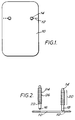
- a chest enclosure includes a base member in the form of a base plate 10 which is generally rectangular in shape and approximately one third of the way along its length has a transverse row of eight threaded through holes 12 arranged in two groups of four, each group lying adjacent to and extending in from one long edge of the plate 10.
- a pair of support members in the form of columns 14 are screwed into respective ones of the holes 12 by means of threaded studs 16 ( Figure 2).
- Each column is circular in cross-section and comprises a first lower plain portion 18 carrying the stud 16 and an upper toothed portion 20 comprising about fifteen frustoconical regions 22 each having an upwardly facing sloping face 24 and a downwardly facing annular face 26 lying parallel to the base plate 10.
- the columns are preferably made of a tough fairly stiff but resilient plastics material.
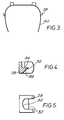
- the shell 40 shown in Figure 3 may be generally conventional except for the provision of a pair of outwardly facing mounting brackets 28 positioned one on each side of the shell toward the top of the shell.
- the shell can be provided with suitable sealing members such that it is in accordance with the second and third aspects of the invention.
- each mounting bracket defines a vertically extending U-shaped channel 30 having a wedge-shaped dog 32 extending out from the base of the channel and providing a horizontal upper semi-circular surface 34 and a downwardly facing sloping rectangular face 36. Below the level of the dog 32, the shape of channel 30 changes to being rectangular rather than U-shaped.
- An alternative manner of use is to first fit the shell 10 pushing the mounting brackets down ratchet-wise between the columns 14 until the patient is lying on the base plate 10.
- the columns of the base plate are easily removed if it is necessary to move the patient.
- the mounting brackets can be released simply by pulling apart the tops of the columns 14.
- the mounting brackets and the formations on the columns 14 may be made such that it is necessary to press the mounting brackets down slightly before they can be released from the columns 14.
- an upstanding lug may be formed on the upper surface 34 of the dog 32 and a downwardly facing co-operating lug may be formed on each annular face 26 of the column 14.
- shell 40 is of springy plastics material having a front edge 42 a side edge 44 and rear edge 46. It comprises a pair of air passageways 48 for connection to a suitable air oscillator, one passageway being provided on each side of the mid line of the shell.
- sealing bead 50 of closed cell resilient foam which extends around the internal face of the shell around the front, side and rear edges in a continuous strip.
- the sealing bead 50 is of generally rectangular cross-section having a rounded nose portion 52.
- a sealing flap 54 of closed cell foam similar to that used for the sealing bead 50 extends from the sealing bead 50.
- Flap 54 is of 5 mm thick foam strip about 2 cm wide. More generally, such a flap is suitably from 3 to 10 mm in thickness, and from 1.5 to 4 cm in width, larger figures within these ranges being more appropriate for larger shells. It is attached by one edge face to the outer root portion of the face of the nose portion 52 of the bead 50, e.g. by adhesive, although of course it could be made integral with the bead 50.
- the flap 54 extends generally at an angle with respect to a perpendicular to the edge of the shell of from about O° to 1O° outwards in the vicinity of the side of the shell to about 0° to 20° inwards in the region of the front of the shell and about O° to 1O° outwards in the region of the rear of the shell.
- the free edge of the flap can be teased outwards to lie on the body of the patient outside of the shell or at least directed towards the outside of the shell so that atmospheric pressure tends to press the flap more tightly against the patient's body.
- a second sealing flap 56 extends inwardly from the bead 50. This is attached to the bead 50 along the nose portion thereof spaced inwardly from the flap 54 by approximately 15 mm. Its dimensions are similar to those of the flap 54 but it is directed toward the interior of the shell so that in use it lies on the body of a patient within the shell and is pressed more tightly against the patient's body in response to super atmospheric pressure in the shell. It extends from the bead 50 at an angle to the adjacent part of the shell of about 5° to 2O° in the region of the sides ( Figure 8) and front (Figure 9) of the shell and about 2O° to 6O° in the region of the back ( Figure 10) of the shell.
- the angle included between the two sealing flaps is about 45° at the back of the shell about 7O° to 9O° along the sides of the shell and about 6O° along the front of the shell.
- the entire sealing structure of bead 50 and flaps 54 and 56 can be made as an integrated whole or assembled from separate constituents.
- the enclosure may be fitted to a patient by springing apart the sides of the shell and passing the sides of the enclosure over the patient's chest and releasing them so that the sealing flaps 54 and 56 seal on the patient's body.
- the flaps, particularly the flap 56 seals against the patient's back so that movement of the patient's ribs is not restricted.
- the shell is fitted with mounting brackets for mounting it to support columns as shown in Figure 1.
- mounting brackets may be as illustrated or may for instance take the form of collars with an adjustment screw passing through the wall of each collar.
- Such collars can be fitted over support columns and held in position by tightening of the screws.
- the shell may be fitted with straps to enable it to be strapped on to a patient. It may be necessary to employ such straps if the patient has a chest region of abnormal shape or if the patient is to be moved wearing the enclosure but the seal provided by the sealing flaps 54 and 56 should under normal circumstances be sufficient to enable the enclosure to be used even before such straps are fitted.
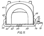
- a backing means in the form of a pad 58 is provided which is a generally rectangular shaped envelope comprising an upper layer 60 and a lower layer 62.
- the layer 60 and layer 62 are attached around their edges so as farm the envelope with interior space 64.
- the space 64 contains sand.
- the pad 58 corresponds generally in shape to a rectangle of a size which is defined by the sides 44, the front 42 and rear 46 edges of the shell 40.
- Side portions 66 of the pad 58 are turned upwards so that portions of the upper layer 60 can be brought into contact with the outside lower edges of the shell 40.
- the side portions 66 of pad 58 are attached to the shell 40 by hook and loop fabric strips 68.
- the pad 58 has an access tube 70 which connects the space 64 with the surrounding atmosphere.
- the tube 70 includes a two-way valve 72.
- a layer of foam rubber 74 is attached to upper layer 62 of the pad 58 in order to insulate and provide the patient with a degree of comfort.
- the pad 58 is spread out flat on a surface.
- the patient is laid face up on the pad 58 and the shell 40 is placed over the patient's chest.
- the weight of the patient deforms the pad 58 so that it forms an impression of the contours of the patient's back.
- the shell 40 is then attached to the upturned portions 66 of the pad 58 by way of the strips 68.
- a vacuum pump (not shown) is connected to pipe 70 and switched on.
- Tap 72 is opened in order to allow air to be drawn out of the space 64.
- the particles are compressed together so that the pad "hardens" and fixes the impression of the patient's back therein. What results is a hard lower surface 62 and a softer upper surface 60.
- the shell 40 and the pad 58 both seal against the patient's body in a substantially air-tight manner so as to completely encase the patient's chest and associated back region.
- the stiffening of the pad 58 causes the upturned side portion connected to the shell 40 to act as support members against any movement of sides of the shell caused by pressure changes inside the shell.
- the hardened pad 58 therefore provides a relatively rigid support for the shell 40 and assists in the sealing of the shell 40 to the patient whilst maintaining a degree of comfort to the patient.
- the pad 58 is made from rubber or a flexible plastics material.
- the space 64 inside the pad 58 can be filled with sand or small particles or beads of plastics material, glass or metal.
Landscapes
- Health & Medical Sciences (AREA)
- Pulmonology (AREA)
- Animal Behavior & Ethology (AREA)
- General Health & Medical Sciences (AREA)
- Heart & Thoracic Surgery (AREA)
- Epidemiology (AREA)
- Pain & Pain Management (AREA)
- Physical Education & Sports Medicine (AREA)
- Rehabilitation Therapy (AREA)
- Life Sciences & Earth Sciences (AREA)
- Cardiology (AREA)
- Emergency Medicine (AREA)
- Public Health (AREA)
- Veterinary Medicine (AREA)
- Building Environments (AREA)
- Percussion Or Vibration Massage (AREA)
- Ventilation (AREA)
- Duct Arrangements (AREA)
- Other Liquid Machine Or Engine Such As Wave Power Use (AREA)
- Prostheses (AREA)
- Respiratory Apparatuses And Protective Means (AREA)
- External Artificial Organs (AREA)
Claims (22)
- Enceinte thoracique à utiliser pour la ventilation assistée des poumons d'un patient, comprenant une coquille couvre-thorax (40) , constituée d'un matériau résilient et destinée à être installée sur le thorax d'un patient, ladite coquille possédant une partie supérieure qui s'étend en travers de la poitrine du patient et des parties latérales qui s'étendent sur les côtés du corps du patient, des moyens (54, 56) permettant de rendre étanche la totalité de la périphérie de la coquille par rapport au thorax du patient, et un passage d'air (48) aménagé dans ladite enceinte et destiné à être raccordé en service à un oscillateur d'air, caractérisée en ce qu'elle comprend en outre une structure de support comportant une base (10) destinée à être disposée sous le dos d'un patient couché, un ou plusieurs éléments de support (14), qui s'élèvent à partir de ladite base, et des moyens (20, 28) permettant d'accrocher ladite coquille audit ou auxdits éléments de support, afin d'empêcher la flexion des parties latérales de la coquille en réponse à une pression inférieure à la pression atmosphérique à l'intérieur de la coquille,.
- Enceinte selon la revendication 1, dans laquelle le ou chaque élément se présente sous la forme d'une colonne de support (14) possédant une série d'emplacements (22) sur sa longueur, au niveau desquels des moyens d'accrochage (28) aménagés sur ladite coquille peuvent entrer en prise avec la colonne, de telle sorte que la hauteur du dessus de la coquille, lorsque la coquille est accrochée aux éléments de support, soit réglable par l'utilisateur.
- Enceinte selon la revendication 1 ou la revendication 2, comprenant au moins une paire desdits éléments de support (14) qui s'élèvent à partir de ladite base, un élément de support de ladite paire étant, en service, disposé de chaque côté du patient, de telle sorte que celui-ci soit allongé entre les éléments de support, et les deux éléments de support de la paire entrent en prise avec la coquille (40) .
- Enceinte selon la revendication 3, dans laquelle les éléments de support (14) entrent en prise avec la coquille (40) en partie supérieure de celle-ci.
- Enceinte selon la revendication 3 ou la revendication 4, dans laquelle un élément de support (14) de la ou de chaque paire d'éléments de support peut être temporairement enlevé de la base (10) pour permettre de soulever le patient.
- Enceinte selon l'une quelconque des revendications 3 à 5, dans laquelle l'espace situé entre les éléments de support de la ou chaque paire d'éléments de support (14) est ouvert vers le haut, de façon à ce qu'un patient portant une coquille (40) d'enceinte thoracique puisse être allongé entre les deux colonnes de la paire et que la coquille puisse ensuite être accrochée aux éléments de support.
- Enceinte selon l'une quelconque des revendications 3 à 6, dans laquelle les éléments de support (14) sont suffisamment flexibles pour être écartés par flexion, de façon à recevoir ladite coquille (40) et à revenir vers l'intérieur par effet ressort pour agripper la coquille située entre eux, et ils sont munis d'une série d'indentations (22) pouvant entrer en prise avec une griffe ou languette (32) prévue sur la partie adjacente de la coquille.
- Enceinte selon l'une quelconque des revendications 1 à 6, dans laquelle est prévu sur la coquille un moyen d'accrochage qui peut dépasser vers l'élément de support pour entrer en prise avec lui, afin de positionner la coquille sur l'élément support.
- Enceinte thoracique selon l'une quelconque des revendications précédentes, caractérisée en ce que lesdits moyens d'étanchéité comprennent une lèvre d'étanchéité (54) en un matériau imperméable à l'air, souple et résilient, qui s'étend de manière continue autour desdites parties de bordure avant, latérales et arrière.
- Enceinte selon la revendication 9, dans laquelle la lèvre (54) a une largeur de 2 à 5 cm et une épaisseur de 3 à 10 mm.
- Enceinte selon la revendication 9 ou la revendication 10, dans laquelle, en service, la lèvre s'étend depuis le bord de la coquille ou depuis une autre garniture d'étanchéité (50) fixée au bord de la coquille, pour entrer en contact avec le corps du patient, et dans une direction telle que son bord libre soit éloigné de l'intérieur de l'enceinte.
- Enceinte selon l'une quelconque des revendications 9 à 11, dans laquelle les parties de la lèvre (54) qui s'étendent le long des parties de bordure latérales de la coquille sont disposées de façon à entrer en contact avec le dos du patient.
- Enceinte selon l'une quelconque des revendications 9 à 12, comprenant en outre un moyen d'adossement (58) à placer derrière le dos du patient en service, et qui est raccordé à ladite coquille, le long des parties latérales de celle-ci, pour maintenir ladite coquille en place, ledit moyen d'adossement (58) comprenant une enveloppe (60, 62) dans laquelle on peut créer une dépression, qui possède une ouverture (70) permettant d'évacuer l'air, et qui contient une multitude de petites particules, de telle sorte que l'enveloppe soit normalement souple et capable d'épouser le corps d'un patient, mais devienne dure lorsque l'air en est évacue.
- Enceinte selon l'une quelconque des revendications 9 à 13, dans laquelle ladite coquille possède une garniture d'étanchéité (54) dirigée vers l'extérieur, en un matériau imperméable à l'air, souple et résilient, qui s'étend sur une partie ou sur la totalité des parties de bordure avant, latérales et arrière de ladite coquille (40) et qui est dirigée de façon à recouvrir, en service, la surface du corps d'un patient, de telle sorte qu'une pression inférieure à la pression atmosphérique, a l'intérieur de ladite enceinte, force ladite garniture d'étanchéité à s'appuyer encore plus contre le corps du patient.
- Enceinte thoracique selon l'une quelconque des revendications précédentes, caractérisée en ce que lesdits moyens d'étanchéité comprennent une garniture d'étanchéité (56) dirigée vers l'intérieur, en un matériau imperméable à l'air, souple et résilient, qui s'étend sur une partie ou sur la totalité des parties de bordure avant, latérales et arrière, et qui est dirigée de façon à recouvrir, en service, la surface du corps d'un patient, de telle sorte qu'une pression supérieure à la pression atmosphérique, à l'intérieur de ladite enceinte, presse ladite garniture d'étanchéité encore plus contre le corps du patient.
- Enceinte selon la revendication 15, dans laquelle ladite garniture d'étanchéité (56) se présente sous la forme d'une lèvre d'étanchéité qui s'étend vers l'intérieur à partir du bord de la coquille ou à partir d'une garniture d'étanchéité (50) fixée au bord de la coquille.
- Enceinte selon la revendication 16, dans laquelle la lèvre (56) s'étend d'une manière continue sur la totalité des parties de bordure avant, arrière et latérales de la coquille.
- Enceinte selon l'une quelconque des revendications 15 à 17, comprenant en outre un moyen d'adossement (58) à placer derrière le dos du patient, en service, et qui est raccordé à ladite coquille, le long des parties latérales de celle-ci, pour maintenir ladite coquille en place, ledit moyen d'adossement (58) comprenant une enveloppe dans laquelle on peut créer une dépression, qui possède une ouverture (70) permettant d'évacuer l'air, et qui contient une multitude de petites particules, de telle sorte que l'enveloppe soit normalement souple et capable d'épouser le corps d'un patient, mais devienne dure lorsque l'air en est évacué.
- Enceinte selon l'une quelconque des revendications précédentes, caractérisée en ce que ladite base (10) comprend une enveloppe (60, 62) dans laquelle on peut créer une dépression, qui possède une ouverture (70) permettant d'évacuer l'air, et qui contient une multitude de petites particules, de telle sorte que l'enveloppe soit normalement souple et capable d'épouser le corps d'un patient, mais devienne dure lorsque l'air en est évacue.
- Enceinte selon la revendication 19, dans laquelle la coquille est raccordée au moyen d'adossement (58), le long des parties latérales de la coquille, d'une manière essentiellement étanche à l'air.
- Enceinte selon la revendication 20, caractérisée en ce que ledit raccordement se fait à l'aide de bandes de tissu (68), mâle-femelle à crochets et à boucles, prévues sur ladite coquille et sur ledit moyen d'adossement.
- Enceinte selon l'une quelconque des revendications 19 à 21, caractérisée en ce que le moyen d'adossement (58) comprend en outre une couche supérieure en un matériau doux (74).
Priority Applications (1)
| Application Number | Priority Date | Filing Date | Title |
|---|---|---|---|
| EP97108894A EP0796601A3 (fr) | 1991-03-28 | 1992-03-27 | Enceinte du thorax pour appareil de respiration artificielle |
Applications Claiming Priority (2)
| Application Number | Priority Date | Filing Date | Title |
|---|---|---|---|
| GB919106717A GB9106717D0 (en) | 1991-03-28 | 1991-03-28 | Chest enclosures for ventilators |
| GB9106717 | 1991-03-28 |
Related Child Applications (1)
| Application Number | Title | Priority Date | Filing Date |
|---|---|---|---|
| EP97108894A Division EP0796601A3 (fr) | 1991-03-28 | 1992-03-27 | Enceinte du thorax pour appareil de respiration artificielle |
Publications (3)
| Publication Number | Publication Date |
|---|---|
| EP0506467A2 EP0506467A2 (fr) | 1992-09-30 |
| EP0506467A3 EP0506467A3 (en) | 1993-01-13 |
| EP0506467B1 true EP0506467B1 (fr) | 1998-01-21 |
Family
ID=10692408
Family Applications (2)
| Application Number | Title | Priority Date | Filing Date |
|---|---|---|---|
| EP92302727A Expired - Lifetime EP0506467B1 (fr) | 1991-03-28 | 1992-03-27 | Enceinte du thorax pour appareil de respiration artificielle |
| EP97108894A Withdrawn EP0796601A3 (fr) | 1991-03-28 | 1992-03-27 | Enceinte du thorax pour appareil de respiration artificielle |
Family Applications After (1)
| Application Number | Title | Priority Date | Filing Date |
|---|---|---|---|
| EP97108894A Withdrawn EP0796601A3 (fr) | 1991-03-28 | 1992-03-27 | Enceinte du thorax pour appareil de respiration artificielle |
Country Status (9)
| Country | Link |
|---|---|
| US (1) | US5573498A (fr) |
| EP (2) | EP0506467B1 (fr) |
| JP (1) | JPH05123374A (fr) |
| AT (1) | ATE162393T1 (fr) |
| AU (3) | AU653794B2 (fr) |
| CA (1) | CA2064281A1 (fr) |
| DE (1) | DE69224096T2 (fr) |
| GB (1) | GB9106717D0 (fr) |
| SG (1) | SG54133A1 (fr) |
Families Citing this family (18)
| Publication number | Priority date | Publication date | Assignee | Title |
|---|---|---|---|---|
| GB9106717D0 (en) * | 1991-03-28 | 1991-05-15 | Dranez Anstalt | Chest enclosures for ventilators |
| GB9410935D0 (en) * | 1994-06-01 | 1994-07-20 | Dranez Anstalt | Ventilator apparatus |
| GB9511423D0 (en) * | 1995-06-06 | 1995-08-02 | Dranez Anstalt | Chest enclosures for ventilators |
| US6533739B1 (en) | 1995-11-21 | 2003-03-18 | The Penn State Research Foundation | Chest brace and method of using same |
| US5769797A (en) | 1996-06-11 | 1998-06-23 | American Biosystems, Inc. | Oscillatory chest compression device |
| GB9615092D0 (en) | 1996-07-18 | 1996-09-04 | Hayek Zamir | Ventilator apparatus |
| US7435233B2 (en) * | 2004-05-27 | 2008-10-14 | Baldy By Design, Llc | Apparatus for mechanically ventilating a patient |
| WO2005117800A2 (fr) * | 2004-05-27 | 2005-12-15 | Baldy By Design Llc | Appareil conçu pour ventiler mecaniquement un patient |
| US20110295163A1 (en) * | 2009-11-24 | 2011-12-01 | Vijayanagar R | Therapeutic hypothermia and cardio-respiratory augmentation apparatus |
| US20140024979A1 (en) | 2010-12-23 | 2014-01-23 | Mark Bruce Radbourne | Respiration-assistance systems, devices, or methods |
| US9855184B2 (en) * | 2013-05-09 | 2018-01-02 | Children's Hospital & Research Center At Oakland | Non-surgical torso deformity correction devices and methods related thereto |
| US12263134B2 (en) | 2015-09-25 | 2025-04-01 | Delta Dynamics Llc | System and methods for pulmonary expansion therapy (PXT) |
| US10478375B2 (en) | 2015-09-25 | 2019-11-19 | Peter Antros | Pulmonary expansion therapy devices |
| TWI678198B (zh) | 2017-11-28 | 2019-12-01 | 財團法人工業技術研究院 | 可調式胸甲 |
| WO2020131736A1 (fr) | 2018-12-17 | 2020-06-25 | The Trustees Of The University Of Pennsylvania | Améliorations de dispositif d'assistance respiratoire ambulatoire |
| WO2021207094A1 (fr) | 2020-04-05 | 2021-10-14 | Mong Michael | Systèmes et méthodes pour le traitement du coronavirus |
| CN115645252B (zh) * | 2022-11-16 | 2023-06-20 | 遂宁市中心医院 | 一种心肺复苏装置 |
| US11839587B1 (en) * | 2023-02-03 | 2023-12-12 | RightAir, Inc. | Systems, devices, and methods for ambulatory respiration assistance |
Family Cites Families (25)
| Publication number | Priority date | Publication date | Assignee | Title |
|---|---|---|---|---|
| DE565434C (de) * | 1932-11-30 | Harald Schumacher Dr | Apparat zur Erzielung kuenstlicher Atmung | |
| US2749910A (en) * | 1956-06-12 | Faulconer | ||
| NL77492C (fr) * | 1900-01-01 | |||
| FR329506A (fr) * | 1903-02-18 | 1903-08-01 | Rudolf Eisenmenger | Appareil pour provoquer la respiration artificielle |
| FR797975A (fr) * | 1934-11-21 | 1936-05-07 | Stille Werner Ab | Perfectionnements aux appareils servant à produire la respiration artificielle |
| DE688387C (de) * | 1936-12-23 | 1940-02-20 | Dr Rudolf Eisenmenger | Brust- und Bauchschild fuer Atmungsapparate |
| US2227847A (en) * | 1937-09-24 | 1941-01-07 | Theodore J Shoolman | Respirator |
| FR862703A (fr) * | 1938-12-14 | 1941-03-13 | Perfectionnements aux appareils pour la respiration artificielle | |
| US2287939A (en) * | 1939-09-21 | 1942-06-30 | Gen Tire & Rubber Co | Respirator |
| US2360476A (en) * | 1942-02-25 | 1944-10-17 | Dunlop Tire & Rubber Corp | Respirator |
| US2466108A (en) * | 1946-10-24 | 1949-04-05 | Thomas C Huxley | Artificial respirator |
| US2772673A (en) * | 1952-06-18 | 1956-12-04 | Conitech Ltd | Artificial respiration apparatus |
| GB752783A (en) * | 1953-12-18 | 1956-07-11 | John Haven Emerson | Improvements in or relating to chest respirators |
| GB763476A (en) * | 1954-02-11 | 1956-12-12 | Medical Supply Ass Ltd | Improvements relating to portable respirators |
| US2759474A (en) * | 1954-06-01 | 1956-08-21 | Conitech Ltd | Artificial respirator |
| GB826003A (en) * | 1954-11-19 | 1959-12-23 | Electronic And X Ray Applic Lt | Improvements in mechanical breathing apparatus |
| US3043292A (en) * | 1959-06-26 | 1962-07-10 | Emanuel S Mendelson | Inflatable, double-walled resuscitation garment |
| US3368550A (en) * | 1965-04-26 | 1968-02-13 | Glascock Harry | Respiratory cuirass |
| US4257407A (en) * | 1977-10-21 | 1981-03-24 | Macchi Pier G | Negative pressure respirator shells |
| DE2805327A1 (de) * | 1978-02-09 | 1979-08-23 | Porsche Ag | Vakuummatratze, vorzugsweise fuer rettungsfahrzeuge |
| GB8501600D0 (en) * | 1985-01-22 | 1985-02-20 | Hayek Z | Infant ventilator |
| WO1987004615A2 (fr) * | 1986-02-04 | 1987-08-13 | Breasy Medical Equipment Limited | Appareil de ventilation pulmonaire et vanne de commande de fluide |
| US4881527A (en) * | 1988-11-14 | 1989-11-21 | Lerman Samuel I | Cardiac assist cuirass |
| GB2226959B (en) * | 1989-01-16 | 1992-11-18 | Zamir Hayek | Chest enclosures for ventilators |
| GB9106717D0 (en) * | 1991-03-28 | 1991-05-15 | Dranez Anstalt | Chest enclosures for ventilators |
-
1991
- 1991-03-28 GB GB919106717A patent/GB9106717D0/en active Pending
-
1992
- 1992-03-27 JP JP4101896A patent/JPH05123374A/ja active Pending
- 1992-03-27 AT AT92302727T patent/ATE162393T1/de not_active IP Right Cessation
- 1992-03-27 EP EP92302727A patent/EP0506467B1/fr not_active Expired - Lifetime
- 1992-03-27 DE DE69224096T patent/DE69224096T2/de not_active Expired - Fee Related
- 1992-03-27 AU AU13875/92A patent/AU653794B2/en not_active Ceased
- 1992-03-27 CA CA002064281A patent/CA2064281A1/fr not_active Abandoned
- 1992-03-27 EP EP97108894A patent/EP0796601A3/fr not_active Withdrawn
- 1992-03-27 SG SG1996001864A patent/SG54133A1/en unknown
-
1994
- 1994-12-07 US US08/350,738 patent/US5573498A/en not_active Expired - Fee Related
-
1995
- 1995-01-11 AU AU10139/95A patent/AU682732B2/en not_active Ceased
- 1995-01-11 AU AU10140/95A patent/AU670401B2/en not_active Ceased
Also Published As
| Publication number | Publication date |
|---|---|
| DE69224096D1 (de) | 1998-02-26 |
| ATE162393T1 (de) | 1998-02-15 |
| JPH05123374A (ja) | 1993-05-21 |
| SG54133A1 (en) | 1998-11-16 |
| AU1013995A (en) | 1995-03-09 |
| CA2064281A1 (fr) | 1992-09-29 |
| AU1387592A (en) | 1992-10-01 |
| AU1014095A (en) | 1995-03-09 |
| EP0506467A3 (en) | 1993-01-13 |
| EP0506467A2 (fr) | 1992-09-30 |
| GB9106717D0 (en) | 1991-05-15 |
| US5573498A (en) | 1996-11-12 |
| EP0796601A3 (fr) | 1997-11-05 |
| AU670401B2 (en) | 1996-07-11 |
| EP0796601A2 (fr) | 1997-09-24 |
| AU653794B2 (en) | 1994-10-13 |
| DE69224096T2 (de) | 1998-09-10 |
| AU682732B2 (en) | 1997-10-16 |
Similar Documents
| Publication | Publication Date | Title |
|---|---|---|
| EP0506467B1 (fr) | Enceinte du thorax pour appareil de respiration artificielle | |
| US5076259A (en) | Chest enclosures for ventilators | |
| US5560354A (en) | Facial masks for assisted respiration or CPAP | |
| AU2009235106B2 (en) | Patient interface system | |
| US4907584A (en) | Respiratory mask | |
| US4003371A (en) | Low pressure hyperbaric chamber | |
| US7152602B2 (en) | Mask apparatus | |
| ES2381478T3 (es) | Aparato de asistencia respiratoria | |
| US4050457A (en) | Sanitary mouth-to-mouth shield | |
| CA2915244C (fr) | Casque pour anesthesie | |
| AU2025204774A1 (en) | Nasal cannula and securement system | |
| US20050284479A1 (en) | Breathing mask with an adhesive seal | |
| US6345618B1 (en) | Cuirass ventilator and seal therefor | |
| US5996581A (en) | Endotracheal tube holder | |
| GB750024A (en) | Artificial respiration apparatus | |
| WO1999061089A1 (fr) | Dispositif servant a empecher ou a limiter le passage d'air a travers la bouche d'un individu | |
| US20060155227A1 (en) | Vacuum splint device | |
| US2227847A (en) | Respirator | |
| CN223490203U (zh) | 一种用于支撑和固定气管插管的装置 | |
| CN213554652U (zh) | 一种改良后的氧气面罩 | |
| WO1996039112A1 (fr) | Enceintes thoraciques pour respirateurs | |
| AU701324B2 (en) | A safety valve for facial masks for assisted respiration or CPAP treatment | |
| AU2005200983B8 (en) | Mask | |
| AU3125199A (en) | A device for preventing or reducing the passage of air through a wearer's mouth | |
| NZ270279A (en) | Head restraint for x-ray machine; includes a flexible body having an open area for receiving a patient's head and freely movable elements within the body position adjustable by suction means |
Legal Events
| Date | Code | Title | Description |
|---|---|---|---|
| PUAI | Public reference made under article 153(3) epc to a published international application that has entered the european phase |
Free format text: ORIGINAL CODE: 0009012 |
|
| AK | Designated contracting states |
Kind code of ref document: A2 Designated state(s): AT BE CH DE DK ES FR GB GR IT LI LU MC NL PT SE |
|
| PUAL | Search report despatched |
Free format text: ORIGINAL CODE: 0009013 |
|
| AK | Designated contracting states |
Kind code of ref document: A3 Designated state(s): AT BE CH DE DK ES FR GB GR IT LI LU MC NL PT SE |
|
| 17P | Request for examination filed |
Effective date: 19930709 |
|
| 17Q | First examination report despatched |
Effective date: 19941219 |
|
| GRAG | Despatch of communication of intention to grant |
Free format text: ORIGINAL CODE: EPIDOS AGRA |
|
| GRAG | Despatch of communication of intention to grant |
Free format text: ORIGINAL CODE: EPIDOS AGRA |
|
| GRAH | Despatch of communication of intention to grant a patent |
Free format text: ORIGINAL CODE: EPIDOS IGRA |
|
| GRAH | Despatch of communication of intention to grant a patent |
Free format text: ORIGINAL CODE: EPIDOS IGRA |
|
| GRAA | (expected) grant |
Free format text: ORIGINAL CODE: 0009210 |
|
| AK | Designated contracting states |
Kind code of ref document: B1 Designated state(s): AT BE CH DE DK ES FR GB GR IT LI LU MC NL PT SE |
|
| DX | Miscellaneous (deleted) | ||
| PG25 | Lapsed in a contracting state [announced via postgrant information from national office to epo] |
Ref country code: NL Free format text: LAPSE BECAUSE OF FAILURE TO SUBMIT A TRANSLATION OF THE DESCRIPTION OR TO PAY THE FEE WITHIN THE PRESCRIBED TIME-LIMIT Effective date: 19980121 Ref country code: LI Free format text: LAPSE BECAUSE OF FAILURE TO SUBMIT A TRANSLATION OF THE DESCRIPTION OR TO PAY THE FEE WITHIN THE PRESCRIBED TIME-LIMIT Effective date: 19980121 Ref country code: GR Free format text: LAPSE BECAUSE OF FAILURE TO SUBMIT A TRANSLATION OF THE DESCRIPTION OR TO PAY THE FEE WITHIN THE PRESCRIBED TIME-LIMIT Effective date: 19980121 Ref country code: ES Free format text: THE PATENT HAS BEEN ANNULLED BY A DECISION OF A NATIONAL AUTHORITY Effective date: 19980121 Ref country code: CH Free format text: LAPSE BECAUSE OF FAILURE TO SUBMIT A TRANSLATION OF THE DESCRIPTION OR TO PAY THE FEE WITHIN THE PRESCRIBED TIME-LIMIT Effective date: 19980121 Ref country code: BE Free format text: LAPSE BECAUSE OF FAILURE TO SUBMIT A TRANSLATION OF THE DESCRIPTION OR TO PAY THE FEE WITHIN THE PRESCRIBED TIME-LIMIT Effective date: 19980121 Ref country code: AT Free format text: LAPSE BECAUSE OF FAILURE TO SUBMIT A TRANSLATION OF THE DESCRIPTION OR TO PAY THE FEE WITHIN THE PRESCRIBED TIME-LIMIT Effective date: 19980121 |
|
| REF | Corresponds to: |
Ref document number: 162393 Country of ref document: AT Date of ref document: 19980215 Kind code of ref document: T |
|
| REG | Reference to a national code |
Ref country code: CH Ref legal event code: EP |
|
| REF | Corresponds to: |
Ref document number: 69224096 Country of ref document: DE Date of ref document: 19980226 |
|
| PG25 | Lapsed in a contracting state [announced via postgrant information from national office to epo] |
Ref country code: LU Free format text: LAPSE BECAUSE OF NON-PAYMENT OF DUE FEES Effective date: 19980327 |
|
| PGFP | Annual fee paid to national office [announced via postgrant information from national office to epo] |
Ref country code: GB Payment date: 19980417 Year of fee payment: 7 |
|
| PGFP | Annual fee paid to national office [announced via postgrant information from national office to epo] |
Ref country code: FR Payment date: 19980420 Year of fee payment: 7 |
|
| ITF | It: translation for a ep patent filed | ||
| PG25 | Lapsed in a contracting state [announced via postgrant information from national office to epo] |
Ref country code: PT Free format text: LAPSE BECAUSE OF FAILURE TO SUBMIT A TRANSLATION OF THE DESCRIPTION OR TO PAY THE FEE WITHIN THE PRESCRIBED TIME-LIMIT Effective date: 19980421 Ref country code: DK Free format text: LAPSE BECAUSE OF FAILURE TO SUBMIT A TRANSLATION OF THE DESCRIPTION OR TO PAY THE FEE WITHIN THE PRESCRIBED TIME-LIMIT Effective date: 19980421 |
|
| PGFP | Annual fee paid to national office [announced via postgrant information from national office to epo] |
Ref country code: SE Payment date: 19980514 Year of fee payment: 7 |
|
| ET | Fr: translation filed | ||
| PGFP | Annual fee paid to national office [announced via postgrant information from national office to epo] |
Ref country code: DE Payment date: 19980529 Year of fee payment: 7 |
|
| NLV1 | Nl: lapsed or annulled due to failure to fulfill the requirements of art. 29p and 29m of the patents act | ||
| REG | Reference to a national code |
Ref country code: CH Ref legal event code: PL |
|
| PG25 | Lapsed in a contracting state [announced via postgrant information from national office to epo] |
Ref country code: MC Free format text: LAPSE BECAUSE OF NON-PAYMENT OF DUE FEES Effective date: 19980930 |
|
| PLBE | No opposition filed within time limit |
Free format text: ORIGINAL CODE: 0009261 |
|
| STAA | Information on the status of an ep patent application or granted ep patent |
Free format text: STATUS: NO OPPOSITION FILED WITHIN TIME LIMIT |
|
| 26N | No opposition filed | ||
| PG25 | Lapsed in a contracting state [announced via postgrant information from national office to epo] |
Ref country code: GB Free format text: LAPSE BECAUSE OF NON-PAYMENT OF DUE FEES Effective date: 19990327 |
|
| PG25 | Lapsed in a contracting state [announced via postgrant information from national office to epo] |
Ref country code: SE Free format text: LAPSE BECAUSE OF NON-PAYMENT OF DUE FEES Effective date: 19990328 |
|
| EUG | Se: european patent has lapsed |
Ref document number: 92302727.0 |
|
| GBPC | Gb: european patent ceased through non-payment of renewal fee |
Effective date: 19990327 |
|
| PG25 | Lapsed in a contracting state [announced via postgrant information from national office to epo] |
Ref country code: FR Free format text: LAPSE BECAUSE OF NON-PAYMENT OF DUE FEES Effective date: 19991130 |
|
| EUG | Se: european patent has lapsed |
Ref document number: 92302727.0 |
|
| REG | Reference to a national code |
Ref country code: FR Ref legal event code: ST |
|
| PG25 | Lapsed in a contracting state [announced via postgrant information from national office to epo] |
Ref country code: DE Free format text: LAPSE BECAUSE OF NON-PAYMENT OF DUE FEES Effective date: 20000101 |
|
| PG25 | Lapsed in a contracting state [announced via postgrant information from national office to epo] |
Ref country code: IT Free format text: LAPSE BECAUSE OF NON-PAYMENT OF DUE FEES;WARNING: LAPSES OF ITALIAN PATENTS WITH EFFECTIVE DATE BEFORE 2007 MAY HAVE OCCURRED AT ANY TIME BEFORE 2007. THE CORRECT EFFECTIVE DATE MAY BE DIFFERENT FROM THE ONE RECORDED. Effective date: 20050327 |