EP0506554B1 - Resonanzdruckfühler - Google Patents
Resonanzdruckfühler Download PDFInfo
- Publication number
- EP0506554B1 EP0506554B1 EP92400805A EP92400805A EP0506554B1 EP 0506554 B1 EP0506554 B1 EP 0506554B1 EP 92400805 A EP92400805 A EP 92400805A EP 92400805 A EP92400805 A EP 92400805A EP 0506554 B1 EP0506554 B1 EP 0506554B1
- Authority
- EP
- European Patent Office
- Prior art keywords
- resonator
- converter
- frame
- pivot
- membrane
- Prior art date
- Legal status (The legal status is an assumption and is not a legal conclusion. Google has not performed a legal analysis and makes no representation as to the accuracy of the status listed.)
- Expired - Lifetime
Links
- 239000012528 membrane Substances 0.000 claims description 34
- 238000005452 bending Methods 0.000 claims description 14
- 239000010453 quartz Substances 0.000 claims description 13
- VYPSYNLAJGMNEJ-UHFFFAOYSA-N silicon dioxide Inorganic materials O=[Si]=O VYPSYNLAJGMNEJ-UHFFFAOYSA-N 0.000 claims description 13
- 239000000463 material Substances 0.000 claims description 10
- 238000004519 manufacturing process Methods 0.000 claims description 9
- 229910052710 silicon Inorganic materials 0.000 claims description 8
- 239000010703 silicon Substances 0.000 claims description 8
- 238000000034 method Methods 0.000 claims description 7
- 238000005459 micromachining Methods 0.000 claims description 7
- 239000000758 substrate Substances 0.000 claims description 7
- 230000000694 effects Effects 0.000 claims description 6
- 230000005284 excitation Effects 0.000 description 8
- 238000001514 detection method Methods 0.000 description 5
- XLOMVQKBTHCTTD-UHFFFAOYSA-N Zinc monoxide Chemical compound [Zn]=O XLOMVQKBTHCTTD-UHFFFAOYSA-N 0.000 description 4
- 230000006835 compression Effects 0.000 description 4
- 238000007906 compression Methods 0.000 description 4
- 238000004377 microelectronic Methods 0.000 description 4
- 238000005530 etching Methods 0.000 description 3
- RTAQQCXQSZGOHL-UHFFFAOYSA-N Titanium Chemical compound [Ti] RTAQQCXQSZGOHL-UHFFFAOYSA-N 0.000 description 2
- 239000003990 capacitor Substances 0.000 description 2
- 239000000470 constituent Substances 0.000 description 2
- 238000005516 engineering process Methods 0.000 description 2
- 229910052719 titanium Inorganic materials 0.000 description 2
- 239000010936 titanium Substances 0.000 description 2
- 239000011787 zinc oxide Substances 0.000 description 2
- 229910052581 Si3N4 Inorganic materials 0.000 description 1
- 238000004458 analytical method Methods 0.000 description 1
- 230000005540 biological transmission Effects 0.000 description 1
- 230000015572 biosynthetic process Effects 0.000 description 1
- 238000006243 chemical reaction Methods 0.000 description 1
- 238000004891 communication Methods 0.000 description 1
- 230000000295 complement effect Effects 0.000 description 1
- 239000012141 concentrate Substances 0.000 description 1
- 230000006378 damage Effects 0.000 description 1
- 230000007547 defect Effects 0.000 description 1
- 238000009826 distribution Methods 0.000 description 1
- 230000007717 exclusion Effects 0.000 description 1
- 238000005468 ion implantation Methods 0.000 description 1
- 238000005259 measurement Methods 0.000 description 1
- 229910021421 monocrystalline silicon Inorganic materials 0.000 description 1
- HQVNEWCFYHHQES-UHFFFAOYSA-N silicon nitride Chemical compound N12[Si]34N5[Si]62N3[Si]51N64 HQVNEWCFYHHQES-UHFFFAOYSA-N 0.000 description 1
- 239000007787 solid Substances 0.000 description 1
- 230000003068 static effect Effects 0.000 description 1
Images

Classifications
-
- G—PHYSICS
- G01—MEASURING; TESTING
- G01L—MEASURING FORCE, STRESS, TORQUE, WORK, MECHANICAL POWER, MECHANICAL EFFICIENCY, OR FLUID PRESSURE
- G01L9/00—Measuring steady of quasi-steady pressure of fluid or fluent solid material by electric or magnetic pressure-sensitive elements; Transmitting or indicating the displacement of mechanical pressure-sensitive elements, used to measure the steady or quasi-steady pressure of a fluid or fluent solid material, by electric or magnetic means
- G01L9/0001—Transmitting or indicating the displacement of elastically deformable gauges by electric, electro-mechanical, magnetic or electro-magnetic means
- G01L9/0008—Transmitting or indicating the displacement of elastically deformable gauges by electric, electro-mechanical, magnetic or electro-magnetic means using vibrations
- G01L9/0022—Transmitting or indicating the displacement of elastically deformable gauges by electric, electro-mechanical, magnetic or electro-magnetic means using vibrations of a piezoelectric element
-
- G—PHYSICS
- G01—MEASURING; TESTING
- G01L—MEASURING FORCE, STRESS, TORQUE, WORK, MECHANICAL POWER, MECHANICAL EFFICIENCY, OR FLUID PRESSURE
- G01L9/00—Measuring steady of quasi-steady pressure of fluid or fluent solid material by electric or magnetic pressure-sensitive elements; Transmitting or indicating the displacement of mechanical pressure-sensitive elements, used to measure the steady or quasi-steady pressure of a fluid or fluent solid material, by electric or magnetic means
- G01L9/0001—Transmitting or indicating the displacement of elastically deformable gauges by electric, electro-mechanical, magnetic or electro-magnetic means
- G01L9/0008—Transmitting or indicating the displacement of elastically deformable gauges by electric, electro-mechanical, magnetic or electro-magnetic means using vibrations
- G01L9/0019—Transmitting or indicating the displacement of elastically deformable gauges by electric, electro-mechanical, magnetic or electro-magnetic means using vibrations of a semiconductive element
Definitions
- the present invention relates to a resonant pressure sensor and in particular to such a small sensor (a few millimeters of coast for example) produced by microelectronics technologies, including in particular micro-machining.
- Such sensors generally comprise a flexible and deformable membrane subjected to the atmosphere in which the pressure to be measured prevails and which transmits, by means of a converter system, the force which it supports due to this pressure to a system.
- resonator also vibrated by an exciter and whose resonant frequency is continuously measured.
- this resonant frequency is a function of the force transmitted to the resonator system, it is clearly seen that by measuring this frequency, an analog quantity representative of the pressure to be measured is obtained.
- the systems used to excite the resonator and measure the resonance frequency belong to many known types and implement physical principles also known.
- FIG. 1 a schematic example of a pressure converter with oscillating quartz conversion belonging to the techniques of the prior art will be described.
- a system comprising a bellows 4 placed in communication by an opening 6 of the wall of the housing 2 with the atmosphere whose pressure is to be measured.
- This bellows 4 which expands more or less in length according to this same pressure acts first on a converter 8 which is a lever-shaped part, articulated around a pivot 10.
- the end 12 of this converter 10 transmits l mechanical action undergone by the bellows 4 on an oscillating quartz 14 whose frequency of resonance is measured.
- This resonant frequency is an analog value of the pressure that we want to measure.
- the currently conceivable manufacturing methods do not make it possible to reduce the size of the sensors below a certain dimension (of the order of 1 or more cm, for example), while more and more applications require small sensors (whose three dimensions are for example of the order of a few millimeters).
- the resonant pressure sensors known to date generally only tolerate frequency deviations of 5 to 10% of the resonant frequency of the resonator which can for example be between 95 to 105 kHz. This feature, which is linked to the breaking stresses of the resonator, significantly limits the range of measurements available for these same sensors.
- a differential pressure sensor comprising a housing containing a resonator and a converter system composed of a tube integral with a pivoting arm around a pivot fixed to the housing.
- the arm is made integral with a deformable membrane and the inside of the housing is isolated from the outside by bellows surrounding the converter tube.
- the present invention specifically relates to a resonant pressure sensor which solves in a simple manner the faults of the prior art as they have just been mentioned, while allowing mass production of the sensors in a miniaturized form.
- This resonant pressure sensor comprising a housing containing a converter and a resonator vibrated by an exciter and the resonance frequency of which is measured is a function of the intensity of the force corresponding to the pressure to be determined, the housing now all of the components of the converter and of the resonator, the converter comprising flexible and bending means capable of absorbing bending moments so as to transmit to the resonator a tensile or compressive force free of bending moment generating stresses localized at the the input of the resonator, is characterized in that the housing is closed by a deformable membrane subjected to the atmosphere in which the pressure to be measured prevails, the converter being mechanically connected to the membrane to transmit the force thus supported by this membrane to the resonator, the housing comprising a rigid frame to hold all of the components of the converter and of the resonator.
- the pressure sensor according to the invention makes it possible to reduce to the strict minimum, or even to remove completely the appearance at the input of the resonator of localized stresses which are dangerous or harmful for the proper functioning thereof and which developed in the sensors of the prior art because no special means were provided in the converter for prevent its formation.
- the system of forces applied by the membrane is transmitted by the converter system to the resonator is not a system of pure forces and includes torques which result from the change in direction of the force applied to the membrane during its transmission. by the converter.
- this structure allows, when is correctly optimized, to transmit to the entry of the beam constituting the resonator practically only pure traction or compression, to the exclusion of any bending moment.
- This makes it possible, by eliminating the risks of destruction of the resonator, to use in particular a much higher range of resonant frequencies whose deviations are of the order of 100% around the central resonant frequency.
- Such a device can for example function perfectly with resonance frequencies which range between 50 and 150 kHz, which gives for example a range of sensor performance which can be between 0 and 50 or 0 and 1 bar with an accuracy of 10 ⁇ 4.
- the resonant pressure sensor which is the subject of the invention has advantages which are complementary to the previous ones when it is moreover miniaturized and produced using micro-electronic techniques or micro-machining.
- the stiffness along the axis of the resonator of the heel-fin-resonator assembly is imposed by the resonator itself while the assembly heel-fins has the sole responsibility of compensating for a residual bending moment at the input of the resonator.
- This is the reason for the shape of the fins connecting the heel to the rigid frame which consist, for example, of vertical blades perpendicular to the plane of the rigid frame preventing practically any rotation of the heel along an axis perpendicular to the longitudinal axis of the rigid frame.
- a resonant pressure sensor as previously defined using the methods of micro-electronic micro-machining, it is done as follows.
- the box comprising the membrane and the rigid frame are manufactured separately from the same material which is chosen from quartz and silicon from a monobloc substrate of this material which is etched to the desired shape using the methods known micromachining.
- the parts thus produced separately are then assembled to form the complete sensor.
- FIG. 2 there is shown the essential part of the resonant sensor, object of the invention which includes the resonator 16, the flexing beam 18, as well as the heel 20 and the pivot 22 located according to the invention inside of the rigid frame 24.
- the assembly shown has a few millimeters on the side and is obtained by etching of a silicon or quartz substrate.
- the pivot 22 is connected to the rigid frame 24 by hinges 26 and the heel 20 is connected to this same rigid frame 24 by a system of fins 28 (two in number in the example shown) which are made up of thin blades perpendicular to the plane of FIG. 2.
- the flexing and flexible beam 18 directly connects the pivot 22 to the heel 20.
- the connection between the heel 20 and the frame 24 can be achieved by a set of beams producing the same compensation effect of a residual bending moment at the input of the resonator.
- the assembly of the pivot 22 of the flexing beam 18 and of the heel 20 transmits the force F on the converter system (22, 18, 20) by absorbing the bending moments so as not to transmit on the resonator 16 consists of a flat beam that a simple tensile or compressive force.
- the reflecting beam 18 is a single beam whose profile is optimized by computer according to the above requirements.
- the resonator 16 is also a simple beam, but could as well in some cases take the structure of a "tuning fork" with several branches. It is clear that the resonance frequency used to measure the pressure can be any of the modes of vibration of this resonator 16, although not all of them are adapted equally to the solution of the problem sought.
- the vibration plane of the resonator is not imposed in principle but rather by technological considerations: it could for example be perpendicular to the plane of the substrate in which it is machined or parallel to this plane, as is the case for example of a resonator produced according to quartz technology.
- the excitation of the resonator 16 is done by creating a small mechanical excitation on its surface using known means and not shown here. If this excitation includes a component (in the sense of the Fourier analysis) whose frequency coincides with the resonance frequency, this component, even very small, is generally sufficient to initiate a vibration of high amplitude.
- the resonant frequency can be detected for example using a deformation detection device; in certain cases also, the resonance is reflected on the exciter device and can be detected and measured by this one.
- the rigid frame 24 When the rigid frame 24 is made of silicon, it is convenient to use an excitation of the electrostatic type with for example a capacitor produced on the surface of the resonator 16 constituting an electrode and a second electrode surmounting a dielectric zone made of silicon nitride Si3F4. Detection can then be done simply using a Wheatstone bridge formed by piezoresistive gauges. In the particular case where the rigid frame 24 is made of quartz, there is every interest in using the piezoelectric property of this material, which then makes it possible to confuse the excitation function and the detection function, since a simple variation in capacity providing electrical excitation is an indication that the system is operating at resonance.
- the function of the converter system (18, 20, 22) is to concentrate the bending forces in the intermediate parts (pivot 22 and flexing beam 18) so as to exclusively exert a net traction (or compression) force on the heel 20
- This heel 20 must therefore exert a sufficiently high return torque to compensate, at their junction point, for the torque due to the flexing beam 18.
- it must oppose a traction (or compression) directed along the main axis. of the resonator 16, the lowest possible resistance.
- the static tensile (or compression) force applied to the heel-resonator assembly is transmitted entirely to the resonator.
- This latter feature of the operation of the sensor is achieved in part thanks to the system of fins 28 which allows longitudinal movement of the heel 20 and on the contrary considerably slows down any attempt to rotate the latter.
- the converter system 30 is designed so that the total moment of the forces, calculated when the resonator 30 is embedded in the heel, or zero without the resulting force directed along the axis of the resonator 16 being zero.
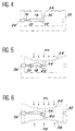
- FIG. 4 we find the converter assembly 18, 20, 22, the resonator 16, mounted together in a parallelepipedic housing 32, the upper surface of which is thinned to form the flexible membrane 34 subjected to the pressure at measure.
- the housing 32 and the membrane 34 are obtained by etching a substrate in the same material.
- Figure 4 shows the lug 36 fixed to the flexible membrane 34 which provides a mechanical link between this membrane 34 and the pivot 22 of the converter.
- FIG. 5 shows the deformation of the structure of FIG. 4 under the effect of a pressure P1 applied to the upper part of the membrane 34. It can be seen that the converter assembly 18, 20, 22 under the effect of the force exerted by the lug 36 on the pivot 26 deforms to adopt a dome profile identical to that which has been shown in FIG. 3.
- the resonant sensor is of the differential type, that is to say that the housing 32 has its two upper and lower faces made up of a flexible membrane, respectively 34 and 38, all of the deformations of the membranes 34 and 38 under the influence of the pressures P1 and P2 applied from the outside transmitting, to the converter assembly by the pins 36 and 40, a resulting deformation.
- the flexible membranes 34 and 38 have an area of a few square millimeters and a thickness of a few micrometers or tens of micrometers. If it is necessary to modify the stiffness of the membranes, can adapt their shape accordingly. In particular, one or more local variations in thickness can make it possible to obtain membranes which, while retaining a fairly high average thickness, nevertheless have a very low stiffness.
- the interior of the housing 32 is designed in a sealed manner and evacuated, which considerably facilitates the vibration of the resonator.
- the process for preparing the previous structure of a miniaturized resonant pressure sensor can consist in separately preparing the rigid frame 24 supporting the converter and the resonator as well as the housing 32 with at least one of its faces constituting the flexible membrane.
- Each of these two parts is produced separately by etching a silicon or quartz substrate, which leads to particularly solid one-piece systems.
- the two parts are then assembled and mounted one inside the other to obtain the complete sensor in FIGS. 4 to 6.
Landscapes
- Physics & Mathematics (AREA)
- General Physics & Mathematics (AREA)
- Measuring Fluid Pressure (AREA)
Claims (3)
- Resonanzdruckfühler, umfassend ein Gehäuse (32), einen Wandler und einen Resonator (16) umschließend, in Schwingung versetzt durch einen Erreger und dessen Resonanzfrequenz, die man mißt, abhängig ist von der Intensität der Kraft, die dem zu bestimmenden Druck entspricht, wobei das Gehäuse die Gesamtheit der Bauteile des Wandlers und des Resonators festhält, der Wandler nachgiebige und biegsame Einrichtungen (18) umfaßt, geeignet zum Absorbieren von Biegemomenten, derart, daß sie an den Resonator eine Zug- oder eine Druckkraft übertragen, befreit von dem am Eingang des Resonators lokalisierte Spannungen erzeugenden Biegemoments,
dadurch gekennzeichnet,
daß das Gehäuse (32) verschlossen ist durch eine verformbare Membran (34), die der Umgebung ausgesetzt ist, in der der zu messende Druck herrscht, wobei der Wandler (18, 20, 22) mechanisch verbunden ist mit der Membran, um die auf diese Membran (34) wirkende Kraft an den Resonator (16) zu übertragen, und das Gehäuse einen steifen Rahmen umfaßt, um die Gesamtheit der Bauteile des Wandlers und des Resonators festzuhalten. - Resonanzdruckfühler nach Anspruch 1, dadurch gekennzeichnet, daß der steife Rahmen (24) rechtwinklig ist und entsprechend seiner Längsachse die folgenden, den Wandler bildenden Bestandteile umfaßt:- einen Dreh- bzw. Gelenkzapfen (22), drehbar um zwei Gelenke (26) angebracht, die ihn verbinden mit den Seitenwänden des Rahmens (24) und dessen Hauptrichtung senkrecht ist zur Längsachse des Rahmens;- einen Ansatz (20), verbunden mit den Wänden des Rahmens durch ein System von Rippen (28), deren Ebene im wesentlichen senkrecht ist zur Ebene des Rahmens;- einen nachgiebigen und biegsamen Träger (18), der den Ansatz (20) und den Zapfen (22) verbindet;- einen als Resonator dienenden Träger (16), der die zum nachgiebigen und biegsamen Träger (18) entgegengesetzte Seite des Ansatzes (20) verbindet mit einer der Seiten des steifen Rahmens (24), die senkrecht ist zur Längsachse des Rahmens, und dadurch, daß der steife Rahmen (24) in der Mittelebene des Gehäuses (32) angebracht ist, das parallelflach ist, und von dem wenigstens eine der zu der Ebene des Rahmens parallelen Seiten gebildet wird durch die Membran (34), verformbar unter der Wirkung des Drucks, dem sie ausgesetzt ist, wobei die Verformungen dieser Membran (34) an den Zapfen übertragen werden durch einen zur Membran (34) gehörenden Vorsprung, der diese Membran und den Ansatz (22) mechanisch verbindet.
- Herstellungsverfahren eines Resonanzdruckfühlers nach einem der vorangehenden Ansprüche 1 und 2 in miniaturisierter Form, dadurch gekennzeichnet, daß die Membran und der steife Rahmen, das Gehäuse bildend, getrennt hergestellt werden aus demselben Material, gewählt zwischen Quartz und Silicium, aus einem Monoblock-Substrat dieses Materials, geätzt mit Hilfe von Mikrobearbeitungsverfahren, dann anschließend zusammengesetzt.
Applications Claiming Priority (2)
| Application Number | Priority Date | Filing Date | Title |
|---|---|---|---|
| FR9103708A FR2674627B1 (fr) | 1991-03-27 | 1991-03-27 | Capteur de pression resonant. |
| FR9103708 | 1991-03-27 |
Publications (2)
| Publication Number | Publication Date |
|---|---|
| EP0506554A1 EP0506554A1 (de) | 1992-09-30 |
| EP0506554B1 true EP0506554B1 (de) | 1996-03-06 |
Family
ID=9411182
Family Applications (1)
| Application Number | Title | Priority Date | Filing Date |
|---|---|---|---|
| EP92400805A Expired - Lifetime EP0506554B1 (de) | 1991-03-27 | 1992-03-25 | Resonanzdruckfühler |
Country Status (5)
| Country | Link |
|---|---|
| US (1) | US5317917A (de) |
| EP (1) | EP0506554B1 (de) |
| JP (1) | JPH0666655A (de) |
| DE (1) | DE69208704T2 (de) |
| FR (1) | FR2674627B1 (de) |
Families Citing this family (27)
| Publication number | Priority date | Publication date | Assignee | Title |
|---|---|---|---|---|
| US5526692A (en) * | 1993-12-29 | 1996-06-18 | Keiser Corporation | Sensor |
| GB9524624D0 (en) * | 1995-12-01 | 1996-01-31 | Weston Aerospace Ltd | Pressure sensor |
| GB2307744B (en) * | 1995-12-01 | 1999-12-01 | Solartron Group Ltd | Pressure sensor |
| US5873840A (en) * | 1997-08-21 | 1999-02-23 | Neff; Samuel R. | Intracranial pressure monitoring system |
| US6182513B1 (en) * | 1998-12-23 | 2001-02-06 | Radi Medical Systems Ab | Resonant sensor and method of making a pressure sensor comprising a resonant beam structure |
| US6165135A (en) * | 1999-07-14 | 2000-12-26 | Neff; Samuel R. | System and method of interrogating implanted passive resonant-circuit devices |
| US6598481B1 (en) * | 2000-03-30 | 2003-07-29 | Halliburton Energy Services, Inc. | Quartz pressure transducer containing microelectronics |
| DE10034390C2 (de) * | 2000-07-14 | 2003-06-26 | Eads Deutschland Gmbh | Drucksensor und Verfahren zu seiner Herstellung, sowie Verbrennungskraftmaschine mit Drucksensor |
| US6532822B1 (en) * | 2000-09-26 | 2003-03-18 | Clark Davis Boyd | Resonant torsion pendulum pressure sensor |
| WO2002101347A1 (en) * | 2001-06-08 | 2002-12-19 | Radi Medical Systems Ab | Miniaturized pressure sensor |
| JP2003083829A (ja) * | 2001-09-12 | 2003-03-19 | Toyo Commun Equip Co Ltd | 圧力センサ |
| US7424376B2 (en) * | 2002-07-25 | 2008-09-09 | Carpenter Brent L | Precise pressure measurement by vibrating an oval conduit along different cross-sectional axes |
| US8162839B2 (en) * | 2003-08-27 | 2012-04-24 | Microtech Medical Technologies Ltd. | Protected passive resonating sensors |
| US7415883B2 (en) * | 2004-06-28 | 2008-08-26 | Zuli Holdings Ltd | Method for protecting resonating sensors and open protected resonating sensors |
| US7800595B2 (en) * | 2003-12-18 | 2010-09-21 | 3M Innovative Properties Company | Piezoelectric transducer |
| DE102004020914B4 (de) * | 2004-04-28 | 2008-05-29 | Max Frank Gmbh & Co Kg | Kragplattenanschlusselement |
| US7490519B2 (en) * | 2005-09-30 | 2009-02-17 | General Electric Company | System and method for sensing differential pressure |
| US20070236213A1 (en) * | 2006-03-30 | 2007-10-11 | Paden Bradley E | Telemetry method and apparatus using magnetically-driven mems resonant structure |
| US7784350B2 (en) * | 2007-02-07 | 2010-08-31 | Halliburton Energy Services, Inc. | Downhole transducer with adjacent heater |
| DE102007000200A1 (de) * | 2007-04-03 | 2008-10-09 | Invendo Medical Gmbh | Druckmesseinrichtung |
| JP4973718B2 (ja) * | 2009-01-27 | 2012-07-11 | セイコーエプソン株式会社 | 圧力検出ユニット、及び圧力センサー |
| FR2977319B1 (fr) | 2011-07-01 | 2014-03-14 | Commissariat Energie Atomique | Dispositif de mesure de pression a sensiblite optimisee |
| US9861524B2 (en) * | 2013-03-14 | 2018-01-09 | New Jersey Institute Of Technology | Smart shunt devices and methods |
| FR3037397B1 (fr) | 2015-06-12 | 2017-06-16 | Sagem Defense Securite | Dispositif de detection de pression a decouplage mecanique |
| FR3098810B1 (fr) * | 2019-07-18 | 2021-10-15 | Commissariat Energie Atomique | Liaison mécanique pour dispositif MEMS et NEMS de mesure d'une variation de pression et dispositif comprenant une telle liaison mécanique |
| CN116381269A (zh) * | 2023-02-17 | 2023-07-04 | 西安近代化学研究所 | 一种基于谐振器的流速传感器及其制备方法 |
| DE102024204085A1 (de) | 2024-05-02 | 2025-11-06 | Robert Bosch Gesellschaft mit beschränkter Haftung | MEMS-Wandlerstruktur |
Family Cites Families (4)
| Publication number | Priority date | Publication date | Assignee | Title |
|---|---|---|---|---|
| US4406966A (en) * | 1980-01-28 | 1983-09-27 | Paroscientific, Inc. | Isolating and temperature compensating system for resonators |
| US4382385A (en) * | 1980-04-17 | 1983-05-10 | Paroscientific, Inc. | Digital differential pressure transducer |
| FR2509856A1 (fr) * | 1981-07-20 | 1983-01-21 | Crouzet Sa | Capteur de pression differentielle |
| GB2215053B (en) * | 1988-02-13 | 1991-09-11 | Stc Plc | Transducer device |
-
1991
- 1991-03-27 FR FR9103708A patent/FR2674627B1/fr not_active Expired - Lifetime
-
1992
- 1992-03-23 US US07/855,312 patent/US5317917A/en not_active Expired - Lifetime
- 1992-03-25 DE DE69208704T patent/DE69208704T2/de not_active Expired - Lifetime
- 1992-03-25 EP EP92400805A patent/EP0506554B1/de not_active Expired - Lifetime
- 1992-03-27 JP JP4101824A patent/JPH0666655A/ja not_active Withdrawn
Also Published As
| Publication number | Publication date |
|---|---|
| JPH0666655A (ja) | 1994-03-11 |
| DE69208704T2 (de) | 1996-10-02 |
| US5317917A (en) | 1994-06-07 |
| FR2674627A1 (fr) | 1992-10-02 |
| FR2674627B1 (fr) | 1994-04-29 |
| EP0506554A1 (de) | 1992-09-30 |
| DE69208704D1 (de) | 1996-04-11 |
Similar Documents
| Publication | Publication Date | Title |
|---|---|---|
| EP0506554B1 (de) | Resonanzdruckfühler | |
| EP3766829B1 (de) | Mechanische verbindung für mems- und nems-vorrichtungen zum messen einer druckveränderung und vorrichtung, die eine solche mechanische verbindung umfasst | |
| EP3538479B1 (de) | Vorrichtung zur übertragung einer bewegung und einer kraft zwischen zwei voneinander isolierten zonen | |
| EP2367015B1 (de) | Rauscharmer kraftsensor | |
| EP2541222B1 (de) | Druckmessgerät mit optimierter Emfpindlichkeit | |
| EP3234536B1 (de) | Dynamischer drucksensor mit verbessertem betrieb | |
| FR2594547A1 (fr) | Transducteur de force a barreau vibrant comportant un seul ressort isolant | |
| FR2963099A1 (fr) | Capteur de pression dynamique mems, en particulier pour des applications a la realisation de microphones | |
| EP2065713B1 (de) | Erfassungsvorrichtung mittels aufgehängtem Dehnungsmesser mit piezoelektrischem Widerstand, der eine Dehnungsverstärkungszelle umfasst | |
| EP0098796A1 (de) | Empfindliches Element für einen Dehnungswandler und Dehnungswandler der es benutzt | |
| CH658910A5 (fr) | Capteur de pression piezo-electrique. | |
| FR2593923A1 (fr) | Capteur accelerometrique et accelerometre le comportant | |
| FR3084167A1 (fr) | Accelerometre a detection par jauge de contraintes a precision amelioree | |
| EP0414588B1 (de) | Beschleunigungsmesser mit Biegeschwinger als Träger | |
| EP0983517A1 (de) | Mikromechanischer beschleunigungsmesser mit kapazitivem resonator | |
| FR2596517A1 (fr) | Transducteur de force a barreau vibrant comportant des moyens de reglage de la frequence de vibration | |
| EP2617129A1 (de) | Vorrichtung mit freihängendem träger und piezoresistive vorrichtung zur verlagerungserkennung sowie verfahren zur herstellung der vorrichtung | |
| EP3886460B1 (de) | Mikroelektromechanisches mikrophon mit reduziertem platzbedarf | |
| FR2664979A1 (fr) | Micro-capteur de pression. | |
| FR2776065A1 (fr) | Capteur de force resonnant a elements piezo-electriques | |
| EP0012644B1 (de) | Beschleunigungsmesser mit akustischen Oberflächenwellen | |
| EP3498661A1 (de) | Mikro- und/oder nanoelektromechanische vorrichtung, die eine erhöhte robustheit bietet | |
| FR3140621A1 (fr) | Dispositif micro-électromécanique | |
| EP2862000B1 (de) | Sensor für magnetfelder mit laplace-kraft | |
| FR3140423A1 (fr) | Capteur inertiel de type MEMS à liaison mécanique spécifique |
Legal Events
| Date | Code | Title | Description |
|---|---|---|---|
| PUAI | Public reference made under article 153(3) epc to a published international application that has entered the european phase |
Free format text: ORIGINAL CODE: 0009012 |
|
| AK | Designated contracting states |
Kind code of ref document: A1 Designated state(s): CH DE GB IT LI NL |
|
| 17P | Request for examination filed |
Effective date: 19930303 |
|
| 17Q | First examination report despatched |
Effective date: 19940502 |
|
| GRAA | (expected) grant |
Free format text: ORIGINAL CODE: 0009210 |
|
| AK | Designated contracting states |
Kind code of ref document: B1 Designated state(s): CH DE GB IT LI NL |
|
| PG25 | Lapsed in a contracting state [announced via postgrant information from national office to epo] |
Ref country code: NL Free format text: LAPSE BECAUSE OF FAILURE TO SUBMIT A TRANSLATION OF THE DESCRIPTION OR TO PAY THE FEE WITHIN THE PRESCRIBED TIME-LIMIT Effective date: 19960306 |
|
| PG25 | Lapsed in a contracting state [announced via postgrant information from national office to epo] |
Ref country code: LI Effective date: 19960331 Ref country code: CH Effective date: 19960331 |
|
| REF | Corresponds to: |
Ref document number: 69208704 Country of ref document: DE Date of ref document: 19960411 |
|
| ITF | It: translation for a ep patent filed | ||
| GBT | Gb: translation of ep patent filed (gb section 77(6)(a)/1977) |
Effective date: 19960515 |
|
| NLV1 | Nl: lapsed or annulled due to failure to fulfill the requirements of art. 29p and 29m of the patents act | ||
| REG | Reference to a national code |
Ref country code: CH Ref legal event code: PL |
|
| PLBE | No opposition filed within time limit |
Free format text: ORIGINAL CODE: 0009261 |
|
| STAA | Information on the status of an ep patent application or granted ep patent |
Free format text: STATUS: NO OPPOSITION FILED WITHIN TIME LIMIT |
|
| 26N | No opposition filed | ||
| REG | Reference to a national code |
Ref country code: GB Ref legal event code: IF02 |
|
| PGFP | Annual fee paid to national office [announced via postgrant information from national office to epo] |
Ref country code: GB Payment date: 20110321 Year of fee payment: 20 Ref country code: DE Payment date: 20110325 Year of fee payment: 20 |
|
| PGFP | Annual fee paid to national office [announced via postgrant information from national office to epo] |
Ref country code: IT Payment date: 20110329 Year of fee payment: 20 |
|
| REG | Reference to a national code |
Ref country code: DE Ref legal event code: R071 Ref document number: 69208704 Country of ref document: DE |
|
| REG | Reference to a national code |
Ref country code: DE Ref legal event code: R071 Ref document number: 69208704 Country of ref document: DE |
|
| REG | Reference to a national code |
Ref country code: GB Ref legal event code: PE20 Expiry date: 20120324 |
|
| PG25 | Lapsed in a contracting state [announced via postgrant information from national office to epo] |
Ref country code: DE Free format text: LAPSE BECAUSE OF EXPIRATION OF PROTECTION Effective date: 20120326 |
|
| PG25 | Lapsed in a contracting state [announced via postgrant information from national office to epo] |
Ref country code: GB Free format text: LAPSE BECAUSE OF EXPIRATION OF PROTECTION Effective date: 20120324 |