EP0506838B1 - Breitbandige kreisförmige phasengesteuerte gruppenantenne - Google Patents
Breitbandige kreisförmige phasengesteuerte gruppenantenne Download PDFInfo
- Publication number
- EP0506838B1 EP0506838B1 EP91902295A EP91902295A EP0506838B1 EP 0506838 B1 EP0506838 B1 EP 0506838B1 EP 91902295 A EP91902295 A EP 91902295A EP 91902295 A EP91902295 A EP 91902295A EP 0506838 B1 EP0506838 B1 EP 0506838B1
- Authority
- EP
- European Patent Office
- Prior art keywords
- phase
- transmission line
- mode
- butler matrix
- antenna
- Prior art date
- Legal status (The legal status is an assumption and is not a legal conclusion. Google has not performed a legal analysis and makes no representation as to the accuracy of the status listed.)
- Expired - Lifetime
Links
- 230000005540 biological transmission Effects 0.000 claims abstract description 65
- 239000011159 matrix material Substances 0.000 claims abstract description 60
- 238000000034 method Methods 0.000 claims abstract description 8
- 230000010363 phase shift Effects 0.000 claims description 9
- 230000005284 excitation Effects 0.000 claims description 6
- 230000008878 coupling Effects 0.000 claims description 3
- 238000010168 coupling process Methods 0.000 claims description 3
- 238000005859 coupling reaction Methods 0.000 claims description 3
- 238000010408 sweeping Methods 0.000 claims 3
- 238000012937 correction Methods 0.000 description 6
- 239000004020 conductor Substances 0.000 description 2
- 238000010586 diagram Methods 0.000 description 2
- 230000000694 effects Effects 0.000 description 2
- 238000005259 measurement Methods 0.000 description 2
- 238000012360 testing method Methods 0.000 description 2
- 208000004350 Strabismus Diseases 0.000 description 1
- 239000004809 Teflon Substances 0.000 description 1
- 229920006362 Teflon® Polymers 0.000 description 1
- 238000004458 analytical method Methods 0.000 description 1
- 238000013459 approach Methods 0.000 description 1
- 238000003491 array Methods 0.000 description 1
- 239000003989 dielectric material Substances 0.000 description 1
- 238000012886 linear function Methods 0.000 description 1
- 230000000750 progressive effect Effects 0.000 description 1
- 230000005855 radiation Effects 0.000 description 1
Images


Classifications
-
- H—ELECTRICITY
- H01—ELECTRIC ELEMENTS
- H01Q—ANTENNAS, i.e. RADIO AERIALS
- H01Q3/00—Arrangements for changing or varying the orientation or the shape of the directional pattern of the waves radiated from an antenna or antenna system
- H01Q3/26—Arrangements for changing or varying the orientation or the shape of the directional pattern of the waves radiated from an antenna or antenna system varying the relative phase or relative amplitude of energisation between two or more active radiating elements; varying the distribution of energy across a radiating aperture
- H01Q3/2682—Time delay steered arrays
- H01Q3/2694—Time delay steered arrays using also variable phase-shifters
-
- H—ELECTRICITY
- H01—ELECTRIC ELEMENTS
- H01Q—ANTENNAS, i.e. RADIO AERIALS
- H01Q3/00—Arrangements for changing or varying the orientation or the shape of the directional pattern of the waves radiated from an antenna or antenna system
- H01Q3/22—Arrangements for changing or varying the orientation or the shape of the directional pattern of the waves radiated from an antenna or antenna system varying the orientation in accordance with variation of frequency of radiated wave
-
- H—ELECTRICITY
- H01—ELECTRIC ELEMENTS
- H01Q—ANTENNAS, i.e. RADIO AERIALS
- H01Q3/00—Arrangements for changing or varying the orientation or the shape of the directional pattern of the waves radiated from an antenna or antenna system
- H01Q3/24—Arrangements for changing or varying the orientation or the shape of the directional pattern of the waves radiated from an antenna or antenna system varying the orientation by switching energy from one active radiating element to another, e.g. for beam switching
- H01Q3/242—Circumferential scanning
Definitions
- This invention relates to a circular phased array antenna fed by a Butler matrix, and more particularly, to phase compensation as a function of frequency at the input modes of the Butler matrix.
- Butler matrix type circular phased array antennas that are used to produce directional antenna beams operate over a narrow frequency band.
- Recent applications using Butler matrix type circular phased array antennas have been for radar beacon systems including interrogation friend or foe (IFF) systems which require only a few percent bandwidth.
- Butler matrix type circular phased array antennas could have many applications, for example, electronic warfare (EW) systems if a directional antenna beam could be produced over a broad bandwidth, for example, one (1) octave.
- EW electronic warfare
- a beam steering control unit is shown coupled to the control inputs of a plurality of phase shifters.
- the phase shifters are shown coupled between a power divider and a Butler matrix and are used for steering the antenna beam.
- an apparatus and method for generating a directional beam having a constant beamwidth over a predetermined frequency bandwidth comprising a circular array antenna, a Butler matrix coupled to the antenna, a plurality of phase shifters, a plurality of transmission line lengths, and a beam forming network or power divider having at least one input and a plurality of outputs for generating the directional beam, each output of the power divider having a predetermined power attenuation with respect to at least one input, each respective output of the power divider coupled in series through a respective phase shifter and a respective transmission line length for providing a predetermined phase decrease as a function of frequency of signals at the respective input mode of the Butler matrix.
- the invention further provides a plurality of transmission line lengths interconnected between the power divider and the Butler matrix to provide phase compensation as a function of frequency at the input modes of the Butler matrix.
- the invention further provides a circular phased array antenna with a Butler matrix having broad band performance, for example, 1.5 octaves.
- the invention further provides a circular phased array antenna fed by a Butler matrix having a constant beam direction and beamwidth over a broad band.
- the invention further provides a circular phased array antenna fed by a Butler matrix with broadband performance with no inherent losses except for ohmic losses due to conductors and dielectric materials.
- the invention further provides a method for empirically determining the transmission line lengths required to provide a predetermined phase decrease as a function of frequency at the input to the Butler Matrix.
- the invention is defined in claim 1, the features of its preamble are known from US-A-4 639 732.
- Fig. 1 is one embodiment of the invention.
- Fig. 2A is a graph of the mode phase bias versus frequency.
- Fig. 2B is a graph of the mode phase bias versus frequency after phase slope compensation.
- Fig. 2C is a graph of the mode phase bias versus frequency after phase slope compensation and phase offset.
- Fig. 3 is a block diagram of the test set-up for measuring the data obtained in Fig. 4.
- Fig. 4 is a graph of the mode phase bias versus frequency obtained with the apparatus of Fig. 3.
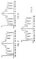
- Fig. 5-9 are graphs of the radiated power versus azimuth for various d/ ⁇ values.
- Circular array antenna system 10 for generating a directional beam having a constant beamwidth over a predetermined frequency bandwidth.
- Circular array antenna system 10 includes a circular array antenna 12, Butler matrix 14, phase shifters 15-23, transmission line lengths 25-33 and power divider 35.
- Phase shifters 15-23 may be, for example, six-bit phase shifters to provide selected variable phase shifts in signals at the inputs of the Butler Matrix in increments of 5.625 degrees of electrical phase.
- Steering circuit 38 functions to send the selected phase settings over steering command lines 37 to cause phase shifters 15-23 to provide selected phase shifts.
- the variable phase shift provided by the phase shifters 15-23 will steer a directional beam in azimuth around circular array antenna 12.
- Antenna array 12 may include a ground plane 40 and antenna elements 41-56 mounted thereon for radiating electromagnetic energy in azimuth at an angle ⁇ and in elevation at an angle ⁇ as shown in Fig. 1.
- Coordinates X, Y and Z are orthogonal to one another. Coordinates X and Y are in the plane of antenna elements 41 through 56.
- Butler matrix 14 may have sixteen output terminals 61-76 which are coupled to respective antenna elements 41-56. Phase shifters 15-23 are coupled over leads 77-85 respectively to input modes of Butler matrix 14. Unused input modes are coupled over leads 86 through 92 to respective terminating resistors 93 through 99.
- Lead 77 is coupled to mode 0.
- Lead 78 is coupled to mode plus 1.
- Lead 79 is coupled to mode minus 1.
- Lead 80 is coupled to mode plus 2.
- Lead 81 is coupled to mode minus 2.
- Lead 82 is coupled to mode plus 3.
- Lead 83 is coupled to mode minus 3.
- Lead 84 is coupled to mode plus 4.
- Lead 85 is coupled to mode minus 4.
- Circular array antenna 12 may have antenna elements 41-56 evenly spaced along a circle having a radius R as shown by arrow 101 and may have antenna element spacing d as shown by arrow 100.
- Power divider 35 has an input lead 102 which may couple microwave power, for example, for a sum pattern and lead 103 which may couple microwave power, for example, for a difference pattern. Power divider 35 functions to divide the power on a respective input lead 102 or 103 to provide weights on the output lines going to transmission line lengths 25-33. The amplitude weights or power division results in a predetermined pattern at a particular frequency being formed from circular array antenna 12. The pattern may be steered through an angle l by a progressive linear phase change produced on phase shifters 15-23 in response to control signals on lead 37 from steering circuit 38. An input to steering circuit 38 on lead 104 may determine the desired steering angle for the beam pattern provided by power divider 35.
- Predetermined and in general different transmission line lengths 25-33 provide a predetermined phase decrease as a function of an increase of frequency of the signal passing through each respective transmission line length.
- phase shifters 15-23 in addition to providing phases to steer the directional beam, provide a fixed phase offset that is the negative of the mode bias phase.
- the fixed phase offset serves to cancel the mode bias phase, since the sum of the fixed phase offset and the mode bias phase will be zero.
- the fixed phase offsets of phase shifters 15-23 are constant with frequency.
- the mode bias phases vary with frequency.
- the mode phase bias is a substantially linear function of frequency for each of the several modes.
- the slope of each respective mode phase versus frequency graph is in general different.
- a line length for example, a radio frequency (R.F.) cable or transmission line, has a phase versus frequency characteristic curve which is linear and the slope of this curve is proportional to the length. Therefore, an appropriate transmission line length placed at each input mode to the Butler matrix will have a phase compensating effect that keeps the directional beam from the circular array antenna 12 focused at different frequencies i.e. over a broad bandwidth.
- the mode bias phase is a fixed phase shift at each particular frequency.
- the mode bias however changes substantially as a function of frequency.
- V l ( ⁇ , ⁇ ) is given by equation 1.
- Mode bias is defined as the complex far field voltage, referenced to the array center, resulting from excitation of the l th mode input of the Butler Matrix 14.
- the mode input excitation has unity amplitude and zero phase when computing mode bias.
- the mode biases are computed for each mode input at a particular value of ⁇ and ⁇ . If the mode excitations are set proportional to the reciprocal of the mode biases, then each mode taken one at time will produce unity voltage in the directions, ⁇ , ⁇ .
- the ideal mode bias correction is given by equation 1.2
- the amplitude A l is not presently described as being corrected herein because the amplitude mainly affects the sidelobes and not the gain or beamwidth of the main beam, for example, a sum beam.
- phase ⁇ l may be corrected as described herein because it keeps the beamwidth and gain of the main beam constant over frequency. Correction of the phase ⁇ l may be achieved without loss of power by using transmission lines as described herein.
- G i equals the voltage gain of the i th antenna element in the direction, ⁇ , ⁇ , shown in Fig. 1 by arrow 107.
- Each antenna element pattern may have a boresight direction B i , which is rotated by an angle ⁇ s with respect to the original angle ⁇ and tilted up in elevation by angle ⁇ s with respect to the original angle ⁇ .
- the angles ⁇ s and ⁇ s are commonly referred to as squint angles with respect to the ⁇ and ⁇ angles.
- the angles ⁇ s and ⁇ s originate at the i th antenna element.
- G i is given in equation 2
- G i 1+KX i
- K is given in equation 3 and X i is given in equation 4.
- K (10 FB/20 -1)/(10 FB/20 +1)
- X i cos ⁇ cos ⁇ s [cos( ⁇ - ⁇ i - ⁇ s )] + sin ⁇ sin ⁇
- FB equals the ith antenna element front to back ratio or maximum to minimum ratio in decibels (dB).
- ⁇ i 2 ⁇ i/N
- i the ith element starting from the X axis and going counterclockwise around the array and N is the number of antenna elements associating with circular array antenna 12.
- ⁇ i is equal to the spatial phase of the ith antenna element referenced to the center of circular array antenna 12 and is given in equation 6.
- ⁇ i R(2 ⁇ / ⁇ )cos ⁇ [cos( ⁇ - ⁇ i )]
- R is equal to the radius of circular array antenna 12.
- ⁇ is equal to the wavelength in inches of the signal to be radiated. ⁇ in inches may be expressed as 12*983.573/f where f is a frequency in megahertz.
- Figs. 2A-2C are graphs of the mode phase bias versus frequency of the signal being radiated for an embodiment similar to that shown in Fig. 1.
- the ordinate represents mode phase bias in degrees and the abscissa represents frequency in megahertz.
- Curves 110-114 were calculated using equation 1 where the radius of the circular array antenna was 33.02 centimeters (13 inches) and the phase was referenced to the center of the circular array antenna where the azimuth angle ⁇ and the elevation angle ⁇ equals zero.
- the element pattern for each antenna element was computed from equation (2) using a front to back ratio (FB) of 100 dB.
- Curves 110-114 correspond to the excitation of mode 0, mode 1, mode 2, mode 3, and mode 4 respectively.
- Reference line 115 is a straight line approximation of curve 110 and has a slope of .398 degrees per Mhz.
- Reference line 116 is a straight line approximation of curve 111 and has a slope of .392 degrees per Mhz.
- Reference line 117 is a straight line approximation of curve 112 and has a slope of .376 degrees per Mhz.
- Reference line 119 is a straight line approximation of curve 113 and has a slope of .355 degrees per Mhz.
- Reference line 123 is a straight line approximation of curve 114 and has a slope of .333 degrees per Mhz.
- 1 is the length of the transmission line
- f is the frequency
- c is the velocity of the signal in the transmission line.
- d ⁇ /df may be expressed as given in equation 8.
- d ⁇ df -360 l c
- Table 1 provides the value of d ⁇ /df as provided by reference lines 115, 116, 117, 119 and 123 in Fig. 2 for respective modes 0, 1, 2, 3 and 4.
- the corresponding length of transmission line or cable to provide a negative d ⁇ /df equal to the positive d ⁇ /df is given in Table 1 in inches.
- the mode phase bias vs. frequency as shown in Fig. 2A may be determined empirically by exciting each mode of the Butler matrix, leads 77-85, and measuring the phase at a particular point in space in the far field with respect to the circular array antenna.
- a signal may be radiated at a particular point in space in the far field with respect to circular array antenna 12 and the phase of the received signal measured at each mode input, leads 77-85, of the Butler matrix.
- exact compensation for each mode phase may be empirically determined by utilizing transmission line stretchers for transmission line lengths 25-33 at the input of each mode of the Butler matrix which would be varied in length by manual adjustment between far field measurements to obtain the same mode phase versus frequency slope for each mode.
- the transmission line stretchers may be left permanently at the inputs of the Butler matrix and the transmission line lengths may be secured by fastening the transmission line stretchers at the length where the change in mode phase over frequency is the same for each mode.
- a RF network analyzer 118 for example a Hewlett-Packard 8510 Network Analyzer manufactured by the Hewlett-Packard Company includes a sweep generator which functions to provide a signal changing with frequency over lead 120 to an antenna element 121 positioned in the far field with respect to the aperture of circular array antenna 12.
- Circular array antenna 12 and Butler matrix 14 receive the radiant energy shown by arrow 122 radiated by antenna element 121 and provides a signal in response thereto at each input mode of Butler matrix 14.
- Each input mode phase of Butler matrix 14 except mode O is coupled one at a time over lead 124 to an input of RF network analyzer generator 118.
- Lead 77 is coupled to a second input to sweep generator 118 wherein the phase of lead 77 is compared with the phase on lead 124 to provide an output on display 126 having a screen 127. If the slope of the curve displayed on display screen 127 has a positive slope as shown by curve 128 in Fig. 4 where the ordinate and abscissa on display screen 127 and Fig. 4 are the same as shown in Fig. 2, then insufficient transmission line length is being used to compensate the more positive slope of the curve of mode phase versus frequency relative to mode O.
- the transmission line length may be mechanically stretched to provide additional length which may be observed after the next sweep of sweep generator 118.
- the curve shown in display screen 127 will approach horizontal as shown by curve 129 in Fig. 4 and in fact may show a negative slope as shown by curve 130 in Fig. 4 as additional transmission line length is added.
- the operator may then adjust the transmission line length to the point where the curve on display screen 127 is horizontal.
- the transmission line length may be measured and a fixed length inserted in its place or the transmission line stretcher may be securely fastened to maintain the line length it had been adjusted to.
- Curve 128 in Figure 4 may show for example the initial slope on display screen 127.
- FIG. 4 shows the desired horizontal slope showing exact compensation relative to the mode O reference and curve 130 in Fig. 4 shows a negative slope where too much transmission line length has been inserted and should be reduced. Fixed phase adjustments are also inserted to bring all modes to the same phase. Normally mode zero is used as the reference phase with respect to the other modes.
- Figs. 5-9 are graphs of the calculated radiated power versus azimuth for various d/ ⁇ values for the embodiment shown in Fig. 1.
- the ordinate represents power in decibels and the abscissa represents azimuth angle in degrees from minus 180 degrees to plus 180 degrees.
- the patterns shown in Figs. 5-9 were computed as a function of inter-element spacing d i.e. spacing/wavelength, which is the same as computing the pattern as a function of frequency.
- d inter-element spacing/wavelength
- Fig. 5 has a d/A spacing equal to .2.
- Fig. 6 has a d/ ⁇ spacing equal to .3.
- Fig. 7 has a d/ ⁇ spacing equal to .4.
- Figs. 8 and 9 have respective d/ ⁇ spacings of .5 and .6.
- the beamwidth is nearly constant from d/ ⁇ equals .2 to .6, a 1.5 octave band.
- a method and apparatus for generating a directional beam having a constant beamwidth over a predetermined frequency bandwidth has been described incorporating a circular array antenna, a Butler matrix coupled to the antenna, a plurality of phase shifters, a plurality of transmission line lengths, and a power divider having at least one input and a plurality of outputs for generating a directional beam, each output of the power divider having a predetermined power attenuation with respect to each input, each respective output of the power divider coupled in series through a respective phase shifter and a respective transmission line length to a respective input mode of the Butler matrix.
- the transmission line length provides a predetermined phase decrease as a function of frequency of the signals at the inputs of the Butler matrix to compensate for changes in mode phase bias of the Butler matrix and circular array antenna due to frequency changes.
- the invention further provides a method for compensating over frequency a circular array antenna coupled to a Butler matrix comprising the steps of coupling a transmission line stretcher to an input mode phase of the Butler matrix, coupling a signal to an antenna in the far field with respect to the circular array antenna, receiving the signal through the circular array antenna and Butler matrix to the respective input mode and comparing the phase of the received mode signal to one of the other modes selected as reference to provide a phase measurement there between and varying the frequency of the signal transmitted over a predetermined frequency range to determine the change in phase difference and adjusting the length of the transmission line stretcher to reduce the change in phase difference over frequency.
Landscapes
- Variable-Direction Aerials And Aerial Arrays (AREA)
Claims (5)
- Kreisförmige, phasengesteuerte Gruppenantenne (10) zum Erzeugen eines lenkbaren Richtstrahles von Radiofrequenzenergie, mit:
einer Mehrzahl von kreisförmig angeordneten Strahlungselementen (41-56);
einer Butler-Matrix (14) mit einer Mehrzahl von Ausgängen (1-16) und einer Mehrzahl von Wellentypeingängen, 1, wobei jeder der Ausgänge der Butler-Matrix durch eine gesonderte Übertragungsleitung einer ersten Gruppe von Übertragungsleitungen (61-76) an ein gesondertes Strahlungselement angekoppelt ist;
einer Mehrzahl von Phasenschiebern (15-23), von denen ein jeder Phasenschieber einen Eingang und einen Ausgang aufweist, wovon jeder Phasenschieberausgang durch eine gesonderte Übertragungsleitung einer zweiten Gruppe von Übertragungsleitungen (77-85) an einen gesonderten Wellentypeingang der Butler-Matrix angekoppelt ist; und
einem Energieteiler (35) mit einem Eingange (102) und einer Mehrzahl von Ausgängen, wovon der Eingang des Energieteilers die von der Antenne als Richtstrahl abzustrahlende Radioenergie aufnimmt und jeder Ausgang des Energieteilers durch eine gesonderte Übertragungsleitung einer dritten Gruppe von Übertragungsleitungen (25-33) an einen gesonderten Phasenschiebereingang angekoppelt ist;
welche Phasenschiebereingänge jeweils eine Phasenverschiebung zwischen ihren Ein- und Ausgängen schaffen, die aus einer festen Phasenabweichung und einer Lenkphase besteht,
wobei die Butler-Matrix, die festen Phasenabweichungen der Phasenschieber und der Energieteiler derart zusammenwirken, daß sie den Richtstrahl bilden,
welcher Richtstrahl entsprechend dem jeweiligen, durch den Ausgang aus dem Energieteiler für die hauptsächliche Erregung ausgewählten Wellentypeingang der Butler-Matrix und dem Werte der durch jeden der Phasenschieber eingeführten Lenkphase in unterschiedliche Richtungen lenkbar ist; dadurch gekennzeichnet, daß:
jede der Übertragungsleitungen (25-33) der dritten Gruppe von Übertragungsleitungen von vorbestimmter Länge ist, so daß eine phasenverschiebung zwischen ihrem zugehörigen Phasenschieber und dem Wellentypeingang eingeführt wird, mit dem der zugehörige Phasenschieber verbunden ist, welche Phasenverschiebung sich mit der Frequenz der an die Übertragungsleitung angelegten Energie um einen Betrag verändert, der gleich und entgegengesetzt der Veränderung der festen Phasenabweichung des zugehörigen phasenschiebers ist, welche bei einer Veränderung der Frequenz der an den zugehörigen phasenschieber angelegten Energie auftritt, wodurch die Richtcharakteristika der Antenne über ein breites Frequenzband der Energie aufrechterhalten werden. - Antenne nach Anspruch 1, bei der jede der vorbestimmten Längen der Übertragungsleitungen (25-33) der dritten Gruppe durch ein Verfahren bestimmt wird, welches aufweist:
Errechnen der Wellentypvorspannung Vl für jeden der Wellentypeingänge, l, der Butler-Matrix der Antenne, um die Wellentypvorspannung in der Form von
Vl die Wellentypvorspannung für den ersten Wellentypeingang der Butler-Matrix ist;
Al die Amplitude der Wellentypvorspannung für den ersten Wellentypeingang der Butler-Matrix ist; und
Φl die Phase der Wellentypvorspannung für den ersten Wellentypeingang der Butler-Matrix ist;
Einstellen der festen Phasenabweichung des dem ersten Wellentypeingang der Butler-Matrix zugeordneten Phasenschiebers, um -Φl gleichzukommen, so daß es gleich und entgegengesetzt der Veränderung der Vorspannungsphasen Φl des Wellentyps ist;
Bestimmen von d/df (-Φl) für die feste Phasenabweichung jedes der phasenschieber;
worin:
d/df (-Φl) die Veränderungsgeschwindigkeit der festen phasenabweichung für den 1. Wellentypeingang der Butler-Matrix hinsichtlich der Frequenz der an den Phasenschieber angelegten Energie ist; und
Vorherbestimmen der jeweiligen Längen Ll für jede jeweilige Übertragungsleitung der dritten Gruppe, welche den Phasenschieber an den 1. Wellentypeingang der Butler-Matrix ankoppelt, so daß die Veränderungsgeschwindigkeit der Phasenverschiebung bezüglich der Frequenz, welche an der von jeder Übertragungsleitung übertragenen Energie auftritt, gleich und entgegengesetzt zu d/df (-Φl) der festen Phasenabweichung des Phasenschiebers ist, an welchen die jeweilige Übertragungsleitung angekoppelt ist. - Antenne nach Anspruch 2, bei der:
jede der vorbestimmten Längen der Übertragungsleitungen (25-33) aus der Beziehung bestimmt wird:
c die Geschwindigkeit der von der Übertragungsleitung übertragenen Energie in dieser Übertragungsleitung ist; und
d/df (-Φl) die Veränderungsgeschwindigkeit der festen Phasenabweichung für den 1. Wellentypeingang der Butler-Matrix ist. - Antenne nach Anspruch 1, bei der jede der vorbestimmten Längen der Übertragungsleitungen (25-33) der dritten Gruppe durch das folgende Verfahren bestimmt ist:
Einbau einer Übertragungsleitung einstellbarer Länge für jede der Übertragungsleitungen (25-33) der dritten Gruppe;
Erregen der Antenne (10) mit Energie von Radiofrequenz (118,120,121,12);
Wobbeln der Frequenz dieser Energie über ein relativ breites Frequenzband (118);
Messen der Phase der am Eingange (124) der einstellbaren, an einen der dem 1. Wellentypeingang zugeordneten Phasenschieber (16) angekoppelten Übertragungsleitung (26) auftretenden Energie (125,126), während die Frequenz der die Antenne erregenden Energie gewobbelt wird;
Einstellen der Länge der Übertragungsleitung einstellbarer Länge, während die Frequenz der die Antenne erregenden Energie gewobbelt wird, bis die Phase der am Eingange der Übertragungsleitung einstellbarer Länge auftretenden Energie konstant bleibt; und
Wiederholen der Verfahrensschritte des Erregens, Wobbelns, Messens und Einstellens für jede der Übertragungsleitungen einstellbarer Länge ihrerseits, bis die Längen aller Übertragungsleitungen einstellbarer Länge, welche mit den den Phasenschiebern aller 1 Wellentypeingänge der Butler-Matrix zugeordneten phasenschiebern verbunden sind, so eingestellt wurden. - Antenne nach Anspruch 4, bei der das Verfahren den zusätzlichen Verfahrensschritt aufweist,
daß nach dem Einstellen der Längen der Übertragungsleitungen einstellbarer Länge jede Übertragungsleitung einstellbarer Länge durch eine Übertragungsleitungen mit fixer Länge ersetzt wird, die der eingestellten Länge jeder der Übertragungsleitungen einstellbarer Länge entspricht.
Applications Claiming Priority (3)
| Application Number | Priority Date | Filing Date | Title |
|---|---|---|---|
| US452453 | 1989-12-18 | ||
| US07/452,453 US4973971A (en) | 1989-12-18 | 1989-12-18 | Broadband circular phased array antenna |
| PCT/US1990/007425 WO1991009433A1 (en) | 1989-12-18 | 1990-12-12 | Broadband circular phased array antenna |
Publications (2)
| Publication Number | Publication Date |
|---|---|
| EP0506838A1 EP0506838A1 (de) | 1992-10-07 |
| EP0506838B1 true EP0506838B1 (de) | 1994-05-04 |
Family
ID=23796515
Family Applications (1)
| Application Number | Title | Priority Date | Filing Date |
|---|---|---|---|
| EP91902295A Expired - Lifetime EP0506838B1 (de) | 1989-12-18 | 1990-12-12 | Breitbandige kreisförmige phasengesteuerte gruppenantenne |
Country Status (6)
| Country | Link |
|---|---|
| US (1) | US4973971A (de) |
| EP (1) | EP0506838B1 (de) |
| JP (1) | JPH05500296A (de) |
| CA (1) | CA2068733A1 (de) |
| DE (1) | DE69008736T2 (de) |
| WO (1) | WO1991009433A1 (de) |
Families Citing this family (19)
| Publication number | Priority date | Publication date | Assignee | Title |
|---|---|---|---|---|
| US5134417A (en) * | 1990-07-23 | 1992-07-28 | Hughes Aircraft Company | Plural frequency matrix multiplexer |
| FR2672436B1 (fr) * | 1991-01-31 | 1993-09-10 | Europ Agence Spatiale | Dispositif de controle electronique du diagramme de rayonnement d'une antenne a un ou plusieurs faisceaux de direction et/ou de largeur variable. |
| US5977910A (en) * | 1997-08-07 | 1999-11-02 | Space Systems/Loral, Inc. | Multibeam phased array antenna system |
| GB9819504D0 (en) * | 1998-09-07 | 1998-10-28 | Ardavan Houshang | Apparatus for generating focused electromagnetic radiation |
| US6198434B1 (en) * | 1998-12-17 | 2001-03-06 | Metawave Communications Corporation | Dual mode switched beam antenna |
| US6583760B2 (en) | 1998-12-17 | 2003-06-24 | Metawave Communications Corporation | Dual mode switched beam antenna |
| US6934511B1 (en) | 1999-07-20 | 2005-08-23 | Andrew Corporation | Integrated repeater |
| US6731904B1 (en) | 1999-07-20 | 2004-05-04 | Andrew Corporation | Side-to-side repeater |
| US6448930B1 (en) | 1999-10-15 | 2002-09-10 | Andrew Corporation | Indoor antenna |
| CA2397430A1 (en) | 2000-01-14 | 2001-07-19 | Breck W. Lovinggood | Repeaters for wireless communication systems |
| ES2192152B1 (es) * | 2002-03-15 | 2005-02-01 | Universidad Politecnica De Valencia | Red conformadora de haces para agrupaciones de antenas basada en matrices opticas de elementos desfasadores/retardadores fijos. |
| US7623868B2 (en) * | 2002-09-16 | 2009-11-24 | Andrew Llc | Multi-band wireless access point comprising coextensive coverage regions |
| US6885343B2 (en) | 2002-09-26 | 2005-04-26 | Andrew Corporation | Stripline parallel-series-fed proximity-coupled cavity backed patch antenna array |
| US20040203804A1 (en) * | 2003-01-03 | 2004-10-14 | Andrew Corporation | Reduction of intermodualtion product interference in a network having sectorized access points |
| RU2310956C1 (ru) * | 2006-09-15 | 2007-11-20 | Закрытое акционерное общество "ИРКОС" | Высоконаправленная кольцевая фазированная антенная решетка |
| WO2013138193A2 (en) | 2012-03-12 | 2013-09-19 | Bar Code Specialties, Inc. (Dba Bcs Solutions) | Rail-mounted robotic inventory system |
| EP3720008A4 (de) * | 2017-11-27 | 2021-07-07 | Tongyu Communication Inc. | Rundstrahlantenne und strahlformungsverfahren dafür |
| RU2716262C1 (ru) * | 2018-11-22 | 2020-03-11 | Андрей Викторович Быков | Способ измерения угла места радиолокационных целей цилиндрической фазированной антенной решеткой |
| CN112600592B (zh) * | 2020-11-27 | 2021-10-08 | 广东纳睿雷达科技股份有限公司 | 巴特勒矩阵相位加权优化方法及巴特勒矩阵 |
Family Cites Families (9)
| Publication number | Priority date | Publication date | Assignee | Title |
|---|---|---|---|---|
| BE757420A (fr) * | 1969-10-13 | 1971-04-13 | Int Standard Electric Corp | Perfectionnement aux systemes radar |
| US4316192A (en) * | 1979-11-01 | 1982-02-16 | The Bendix Corporation | Beam forming network for butler matrix fed circular array |
| US4348679A (en) * | 1980-10-06 | 1982-09-07 | United Technologies Corporation | Multi-mode dual-feed array radar antenna |
| US4414550A (en) * | 1981-08-04 | 1983-11-08 | The Bendix Corporation | Low profile circular array antenna and microstrip elements therefor |
| DE3311569A1 (de) * | 1983-03-30 | 1984-10-04 | Standard Elektrik Lorenz Ag, 7000 Stuttgart | Tacan-drehfunkfeuer |
| IT1179394B (it) * | 1984-07-09 | 1987-09-16 | Selenia Ind Elettroniche | Antenna multifascio in grado di realizzare posizioni di fascio diverse in funzione del settore angolare di interesse |
| US4652879A (en) * | 1985-02-11 | 1987-03-24 | Eaton Corporation | Phased array antenna system to produce wide-open coverage of a wide angular sector with high directive gain and strong capability to resolve multiple signals |
| US4639732A (en) * | 1985-02-22 | 1987-01-27 | Allied Corporation | Integral monitor system for circular phased array antenna |
| EP0215971A1 (de) * | 1985-09-24 | 1987-04-01 | Allied Corporation | Antenne speisendes Netzwerk |
-
1989
- 1989-12-18 US US07/452,453 patent/US4973971A/en not_active Expired - Fee Related
-
1990
- 1990-12-12 CA CA002068733A patent/CA2068733A1/en not_active Abandoned
- 1990-12-12 EP EP91902295A patent/EP0506838B1/de not_active Expired - Lifetime
- 1990-12-12 DE DE69008736T patent/DE69008736T2/de not_active Expired - Fee Related
- 1990-12-12 JP JP91502351A patent/JPH05500296A/ja active Pending
- 1990-12-12 WO PCT/US1990/007425 patent/WO1991009433A1/en not_active Ceased
Also Published As
| Publication number | Publication date |
|---|---|
| JPH05500296A (ja) | 1993-01-21 |
| EP0506838A1 (de) | 1992-10-07 |
| CA2068733A1 (en) | 1991-06-19 |
| WO1991009433A1 (en) | 1991-06-27 |
| DE69008736T2 (de) | 1994-08-18 |
| DE69008736D1 (de) | 1994-06-09 |
| US4973971A (en) | 1990-11-27 |
Similar Documents
| Publication | Publication Date | Title |
|---|---|---|
| EP0506838B1 (de) | Breitbandige kreisförmige phasengesteuerte gruppenantenne | |
| US6686873B2 (en) | Farfield calibration method used for phased array antennas containing tunable phase shifters | |
| US6771216B2 (en) | Nearfield calibration method used for phased array antennas containing tunable phase shifters | |
| EP0126626B1 (de) | Resonanzhohlleiterschalter für strahlende Öffnung | |
| Fukao et al. | The MU radar with an active phased array system: 1. Antenna and power amplifiers | |
| DE602004005635T2 (de) | Vorrichtung und Verfahren zur Kompensation der Depolarisation eines Radoms | |
| US6975268B2 (en) | Phased array antenna including a distributed phase calibrator and associated method | |
| US5235342A (en) | Antenna array with system for locating and adjusting phase centers of elements of the antenna array | |
| US4654666A (en) | Passive frequency scanning radiometer | |
| US12562475B2 (en) | Electronic scanning antenna | |
| CN117155486A (zh) | 一种桌面与外场相结合的相控阵阵面校准方法 | |
| US20240250408A1 (en) | Antenna device and wireless device | |
| CA1203296A (en) | Asymmetric resonant waveguide aperture manifold | |
| JPH0338548B2 (de) | ||
| Wilensky | High-power, broad-bandwidth HF dipole curtain array with extensive vertical and azimuthal beam control | |
| CA1203297A (en) | Resonant waveguide aperture manifold | |
| EP0415574A2 (de) | Gruppenantenne | |
| Dunn et al. | Design of an eight element edge slot waveguide array antenna | |
| KR940000797B1 (ko) | 위상-어레이 안테나용 방사소자 | |
| Jones et al. | Broadband pattern synthesis from a circular array | |
| Kobayashi | A novel butler matrix based beam forming network architecture for multiple antenna beam steering | |
| Chen et al. | Azimuth scanning, Ka-band phased array antenna | |
| Zhang et al. | Design of Low Cross Polarization Phased Antenna Arrays for X-band Spaceborne SAR Applications | |
| Huisjen | Prediction of antenna array performance from subarray measurements | |
| Roth et al. | Highly shaped satellite antenna for constant flux illumination of the earth from low orbits |
Legal Events
| Date | Code | Title | Description |
|---|---|---|---|
| PUAI | Public reference made under article 153(3) epc to a published international application that has entered the european phase |
Free format text: ORIGINAL CODE: 0009012 |
|
| 17P | Request for examination filed |
Effective date: 19920515 |
|
| AK | Designated contracting states |
Kind code of ref document: A1 Designated state(s): DE FR GB IT |
|
| 17Q | First examination report despatched |
Effective date: 19931006 |
|
| RAP1 | Party data changed (applicant data changed or rights of an application transferred) |
Owner name: ALLIEDSIGNAL INC. |
|
| GRAA | (expected) grant |
Free format text: ORIGINAL CODE: 0009210 |
|
| ITF | It: translation for a ep patent filed | ||
| AK | Designated contracting states |
Kind code of ref document: B1 Designated state(s): DE FR GB IT |
|
| REF | Corresponds to: |
Ref document number: 69008736 Country of ref document: DE Date of ref document: 19940609 |
|
| ET | Fr: translation filed | ||
| PLBE | No opposition filed within time limit |
Free format text: ORIGINAL CODE: 0009261 |
|
| STAA | Information on the status of an ep patent application or granted ep patent |
Free format text: STATUS: NO OPPOSITION FILED WITHIN TIME LIMIT |
|
| 26N | No opposition filed | ||
| REG | Reference to a national code |
Ref country code: GB Ref legal event code: 746 Effective date: 19951116 |
|
| REG | Reference to a national code |
Ref country code: FR Ref legal event code: D6 |
|
| REG | Reference to a national code |
Ref country code: GB Ref legal event code: 746 Effective date: 19960214 |
|
| PGFP | Annual fee paid to national office [announced via postgrant information from national office to epo] |
Ref country code: GB Payment date: 19961108 Year of fee payment: 7 |
|
| PGFP | Annual fee paid to national office [announced via postgrant information from national office to epo] |
Ref country code: FR Payment date: 19961211 Year of fee payment: 7 |
|
| PGFP | Annual fee paid to national office [announced via postgrant information from national office to epo] |
Ref country code: DE Payment date: 19961227 Year of fee payment: 7 |
|
| PG25 | Lapsed in a contracting state [announced via postgrant information from national office to epo] |
Ref country code: GB Free format text: LAPSE BECAUSE OF NON-PAYMENT OF DUE FEES Effective date: 19971212 |
|
| PG25 | Lapsed in a contracting state [announced via postgrant information from national office to epo] |
Ref country code: FR Free format text: THE PATENT HAS BEEN ANNULLED BY A DECISION OF A NATIONAL AUTHORITY Effective date: 19971231 |
|
| GBPC | Gb: european patent ceased through non-payment of renewal fee |
Effective date: 19971212 |
|
| PG25 | Lapsed in a contracting state [announced via postgrant information from national office to epo] |
Ref country code: DE Free format text: LAPSE BECAUSE OF NON-PAYMENT OF DUE FEES Effective date: 19980901 |
|
| REG | Reference to a national code |
Ref country code: FR Ref legal event code: ST |
|
| PG25 | Lapsed in a contracting state [announced via postgrant information from national office to epo] |
Ref country code: IT Free format text: LAPSE BECAUSE OF NON-PAYMENT OF DUE FEES;WARNING: LAPSES OF ITALIAN PATENTS WITH EFFECTIVE DATE BEFORE 2007 MAY HAVE OCCURRED AT ANY TIME BEFORE 2007. THE CORRECT EFFECTIVE DATE MAY BE DIFFERENT FROM THE ONE RECORDED. Effective date: 20051212 |