EP0507100A1 - Procédé d'introduction d'une tige de perçage dans le trou de coulée d'un four à cuve, machine de perçage et pince bi-directionnelle - Google Patents
Procédé d'introduction d'une tige de perçage dans le trou de coulée d'un four à cuve, machine de perçage et pince bi-directionnelle Download PDFInfo
- Publication number
- EP0507100A1 EP0507100A1 EP92103828A EP92103828A EP0507100A1 EP 0507100 A1 EP0507100 A1 EP 0507100A1 EP 92103828 A EP92103828 A EP 92103828A EP 92103828 A EP92103828 A EP 92103828A EP 0507100 A1 EP0507100 A1 EP 0507100A1
- Authority
- EP
- European Patent Office
- Prior art keywords
- rod
- jaws
- clamp
- carriage
- jaw
- Prior art date
- Legal status (The legal status is an assumption and is not a legal conclusion. Google has not performed a legal analysis and makes no representation as to the accuracy of the status listed.)
- Withdrawn
Links
- 238000000034 method Methods 0.000 title claims abstract description 17
- 238000005553 drilling Methods 0.000 title claims abstract description 15
- 230000008569 process Effects 0.000 title claims description 3
- 238000000605 extraction Methods 0.000 claims abstract description 29
- 230000009471 action Effects 0.000 claims abstract description 13
- 230000008878 coupling Effects 0.000 claims description 14
- 238000010168 coupling process Methods 0.000 claims description 14
- 238000005859 coupling reaction Methods 0.000 claims description 14
- 239000012530 fluid Substances 0.000 claims description 8
- 230000000284 resting effect Effects 0.000 claims 2
- 230000008901 benefit Effects 0.000 description 4
- 238000006243 chemical reaction Methods 0.000 description 3
- 238000007789 sealing Methods 0.000 description 3
- 238000004140 cleaning Methods 0.000 description 2
- 239000000428 dust Substances 0.000 description 2
- 238000003780 insertion Methods 0.000 description 2
- 230000037431 insertion Effects 0.000 description 2
- 230000001154 acute effect Effects 0.000 description 1
- 230000006978 adaptation Effects 0.000 description 1
- 230000000903 blocking effect Effects 0.000 description 1
- 238000005266 casting Methods 0.000 description 1
- 230000015556 catabolic process Effects 0.000 description 1
- 150000001875 compounds Chemical class 0.000 description 1
- 230000001934 delay Effects 0.000 description 1
- 229910003460 diamond Inorganic materials 0.000 description 1
- 239000010432 diamond Substances 0.000 description 1
- 230000000694 effects Effects 0.000 description 1
- 230000008030 elimination Effects 0.000 description 1
- 238000003379 elimination reaction Methods 0.000 description 1
- 238000009434 installation Methods 0.000 description 1
- 230000002452 interceptive effect Effects 0.000 description 1
- 239000000463 material Substances 0.000 description 1
- 239000002184 metal Substances 0.000 description 1
- 238000012986 modification Methods 0.000 description 1
- 230000004048 modification Effects 0.000 description 1
- 239000012768 molten material Substances 0.000 description 1
- 230000035515 penetration Effects 0.000 description 1
- 238000009527 percussion Methods 0.000 description 1
- 229920005989 resin Polymers 0.000 description 1
- 239000011347 resin Substances 0.000 description 1
- 238000007711 solidification Methods 0.000 description 1
- 230000008023 solidification Effects 0.000 description 1
- 238000006467 substitution reaction Methods 0.000 description 1
Images


Classifications
-
- C—CHEMISTRY; METALLURGY
- C21—METALLURGY OF IRON
- C21B—MANUFACTURE OF IRON OR STEEL
- C21B7/00—Blast furnaces
- C21B7/12—Opening or sealing the tap holes
Definitions
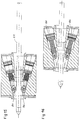
- the invention also relates to a drilling machine which can be used for extracting and inserting a drilling rod into the tap hole of a shaft furnace, comprising a working tool with a coupling means at the end. free from the rod and movable along a carriage bearing on the wall of the oven, a clamp mounted on the carriage, in axial alignment with the coupling device and movable longitudinally with respect to the carriage, under the action of a hydraulic cylinder mounted thereon, characterized in that said clamp is a bi-directional clamp acting under the action of a pneumatic or hydraulic fluid, either in one direction or in the opposite direction.
- the invention also relates to a bi-directional clamp designed for such a machine and comprising two pairs of jaws arranged symmetrically around an axial channel capable of receiving a piercing rod, and displaceable obliquely with respect to said channel, the pair of jaws on the furnace side being oriented towards the front for the extraction of the rod and the pair of jaws on the opposite side being oriented towards the rear for the introduction of the rod.
- the clamp comprises two pairs of jaws, arranged in a cross, in the same housing block, the two jaws of each pair being arranged symmetrically around an axial channel of the housing block and displaceable obliquely relative to to said channel, one of the pairs of jaws being oriented towards the front for the extraction of the rod and the other pair of jaws being oriented towards the rear for the introduction of the rod.
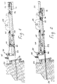
- the rod 22 When the rod 22 extends to the front end of the mount, it is preferable, so as not to have to thread it axially through the clamp, to use an open clamp as described below, in order to be able to engage the rod laterally in the clamp.
- an open clamp As described below, in order to be able to engage the rod laterally in the clamp.
- the clamp 46 On the other hand, if the rod 22 is shorter, or the carriage longer, it is possible to completely advance the clamp 46, to engage the rod 22 in the mandrel 36, to place it, in cantilever , on the support 38 and engage the clamp 46 axially, moving back, around the rod, the clamp can, therefore, be a closed clamp.
- the carriage 26 With the wall of the furnace 20.
- the lock 40 it suffices to manually engage or by an automatic system the lock 40 to ensure the male connection and female at the support 40. This locking makes it possible to absorb the counter-reaction forces to the right when the rod 22 is pressed under the action of the jack 42.
- the latch 40 is raised to release the support 34 from the wall of the oven and to be able to withdraw the machine towards the garage position and abandon the rod 22 in the position according to FIG. 4.
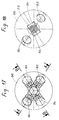
- FIG. 11 shows an axial view of a clamp 70 according to FIG. 10.
- the clamp 70 is fixed, for example screwed, on a shoe 80 actuated by the rod 44 of the piston 42 (FIG. 1) and intended to slide between two beams 26a, 26b forming the mount 26.
- the jaws are provided above and below the channel 76 which opens by a groove 88 to the side.
Landscapes
- Engineering & Computer Science (AREA)
- Chemical & Material Sciences (AREA)
- Manufacturing & Machinery (AREA)
- Materials Engineering (AREA)
- Metallurgy (AREA)
- Organic Chemistry (AREA)
- Blast Furnaces (AREA)
- Automatic Assembly (AREA)
Applications Claiming Priority (4)
| Application Number | Priority Date | Filing Date | Title |
|---|---|---|---|
| LU87915A LU87915A1 (fr) | 1991-04-03 | 1991-04-03 | Procede d'introduction d'une tige de percage dans le trou de coulee d'un four a cuve,machine de percage et pince prevue pour une telle machine |
| LU87915 | 1991-04-03 | ||
| LU88020A LU88020A1 (fr) | 1991-10-16 | 1991-10-16 | Procédé d'introduction d'un tige de perçage dans le trou de coulée d'un four à cuve, machine de perçage et pince grévue pour une telle machine |
| LU88020 | 1991-10-16 |
Publications (1)
| Publication Number | Publication Date |
|---|---|
| EP0507100A1 true EP0507100A1 (fr) | 1992-10-07 |
Family
ID=26640340
Family Applications (1)
| Application Number | Title | Priority Date | Filing Date |
|---|---|---|---|
| EP92103828A Withdrawn EP0507100A1 (fr) | 1991-04-03 | 1992-03-06 | Procédé d'introduction d'une tige de perçage dans le trou de coulée d'un four à cuve, machine de perçage et pince bi-directionnelle |
Country Status (11)
| Country | Link |
|---|---|
| EP (1) | EP0507100A1 (cs) |
| JP (1) | JPH05132706A (cs) |
| CN (1) | CN1027181C (cs) |
| AU (1) | AU1282192A (cs) |
| BR (1) | BR9201335A (cs) |
| CA (1) | CA2064936A1 (cs) |
| CS (1) | CS96892A3 (cs) |
| DE (1) | DE4207491A1 (cs) |
| FI (1) | FI921408L (cs) |
| PL (1) | PL294067A1 (cs) |
| TR (1) | TR26383A (cs) |
Cited By (2)
| Publication number | Priority date | Publication date | Assignee | Title |
|---|---|---|---|---|
| FR2687688A1 (fr) * | 1992-01-27 | 1993-08-27 | Wurth Paul Sa | Machine de percage d'un trou de coulee d'un four a cuve. |
| GB2260189B (en) * | 1991-09-26 | 1996-04-10 | Dango & Dienenthal Maschbau | A tapping hole boring machine for metallurgical containers,especially blast furnaces |
Families Citing this family (2)
| Publication number | Priority date | Publication date | Assignee | Title |
|---|---|---|---|---|
| CN101619370B (zh) * | 2009-08-10 | 2010-09-29 | 重庆钢铁(集团)有限责任公司 | 快速消除称量料罐底部堵料的结构 |
| EP2415881B1 (de) * | 2010-08-04 | 2013-12-25 | TMT Tapping-Measuring-Technology GmbH | Haltevorrichtung für eine Bohrstange einer Stichlochbohrmaschine sowie Verfahren zum Entfernen einer Bohrstange |
Citations (6)
| Publication number | Priority date | Publication date | Assignee | Title |
|---|---|---|---|---|
| DE2153297A1 (de) * | 1970-10-26 | 1972-05-25 | Intreprinderea de Retele Elctrice Tirgu-Mures, Tirgu-Mures (Rumänien) | Vorrichtung zum horizontalen Unterbohren von Straßen- und Schienenverkehrswegen oder dgl |
| US3834668A (en) * | 1973-01-11 | 1974-09-10 | J Casey | Pipe pushing apparatus |
| US4000879A (en) * | 1974-10-23 | 1977-01-04 | The Charles Machine Works, Inc. | Pushing or pulling apparatus for pipe, rod or the like |
| US4455107A (en) * | 1982-07-02 | 1984-06-19 | Elephant Industries, Inc. | Pipe and cable installers |
| EP0379018A2 (fr) * | 1989-01-16 | 1990-07-25 | Paul Wurth S.A. | Procédé et dispositif d'ouverture du trou de coulée d'un four à cuve |
| US4955757A (en) * | 1989-06-29 | 1990-09-11 | Curtis Balling | Hydraulic apparatus for installing piping below ground |
-
1992
- 1992-03-06 EP EP92103828A patent/EP0507100A1/fr not_active Withdrawn
- 1992-03-10 DE DE4207491A patent/DE4207491A1/de not_active Withdrawn
- 1992-03-12 AU AU12821/92A patent/AU1282192A/en not_active Abandoned
- 1992-03-31 FI FI921408A patent/FI921408L/fi not_active Application Discontinuation
- 1992-04-01 CS CS92968A patent/CS96892A3/cs unknown
- 1992-04-01 PL PL29406792A patent/PL294067A1/xx unknown
- 1992-04-02 TR TR92/0291A patent/TR26383A/xx unknown
- 1992-04-02 CN CN92102342.1A patent/CN1027181C/zh not_active Expired - Fee Related
- 1992-04-02 JP JP4110805A patent/JPH05132706A/ja active Pending
- 1992-04-02 BR BR929201335A patent/BR9201335A/pt not_active Application Discontinuation
- 1992-04-02 CA CA002064936A patent/CA2064936A1/fr not_active Abandoned
Patent Citations (6)
| Publication number | Priority date | Publication date | Assignee | Title |
|---|---|---|---|---|
| DE2153297A1 (de) * | 1970-10-26 | 1972-05-25 | Intreprinderea de Retele Elctrice Tirgu-Mures, Tirgu-Mures (Rumänien) | Vorrichtung zum horizontalen Unterbohren von Straßen- und Schienenverkehrswegen oder dgl |
| US3834668A (en) * | 1973-01-11 | 1974-09-10 | J Casey | Pipe pushing apparatus |
| US4000879A (en) * | 1974-10-23 | 1977-01-04 | The Charles Machine Works, Inc. | Pushing or pulling apparatus for pipe, rod or the like |
| US4455107A (en) * | 1982-07-02 | 1984-06-19 | Elephant Industries, Inc. | Pipe and cable installers |
| EP0379018A2 (fr) * | 1989-01-16 | 1990-07-25 | Paul Wurth S.A. | Procédé et dispositif d'ouverture du trou de coulée d'un four à cuve |
| US4955757A (en) * | 1989-06-29 | 1990-09-11 | Curtis Balling | Hydraulic apparatus for installing piping below ground |
Cited By (2)
| Publication number | Priority date | Publication date | Assignee | Title |
|---|---|---|---|---|
| GB2260189B (en) * | 1991-09-26 | 1996-04-10 | Dango & Dienenthal Maschbau | A tapping hole boring machine for metallurgical containers,especially blast furnaces |
| FR2687688A1 (fr) * | 1992-01-27 | 1993-08-27 | Wurth Paul Sa | Machine de percage d'un trou de coulee d'un four a cuve. |
Also Published As
| Publication number | Publication date |
|---|---|
| CN1065492A (zh) | 1992-10-21 |
| AU1282192A (en) | 1992-10-08 |
| FI921408A7 (fi) | 1992-10-04 |
| JPH05132706A (ja) | 1993-05-28 |
| FI921408A0 (fi) | 1992-03-31 |
| CA2064936A1 (fr) | 1992-10-04 |
| CN1027181C (zh) | 1994-12-28 |
| CS96892A3 (en) | 1992-10-14 |
| TR26383A (tr) | 1995-03-15 |
| BR9201335A (pt) | 1992-12-01 |
| DE4207491A1 (de) | 1992-10-08 |
| FI921408L (fi) | 1992-10-04 |
| PL294067A1 (en) | 1992-10-19 |
Similar Documents
| Publication | Publication Date | Title |
|---|---|---|
| FR2587246A1 (fr) | Appareil automatique pour poser des pieces de fixation telles que des rivets | |
| CH652799A5 (fr) | Dispositif pour la reception des boulons et leur maintien en cours de pose. | |
| FR2494414A1 (fr) | Tete de guidage et de support d'une tige de percage du trou de coulee d'un four a cuve et perceuse pourvue d'une telle tete | |
| FR2649937A1 (fr) | Dispositif de tirage pour un organe de fermeture de vehicule automobile, notamment une capote repliable | |
| FR2540772A1 (fr) | Outil automatique de vissage de goujons | |
| EP0379018A2 (fr) | Procédé et dispositif d'ouverture du trou de coulée d'un four à cuve | |
| EP0825910B1 (fr) | Dispositif et procede de changement d'un tube de coulee continue de repartiteur d'acierie | |
| CA2064936A1 (fr) | Procede d'introduction d'une tige de percage dans le trou de coulee d'un four a cuve, machine de percage et pince bi-directionnelle | |
| LU84855A1 (fr) | Machine de percage d'un trou de coulee de four a cuve | |
| EP0552476B1 (fr) | Machine de perçage d'un trou de coulée d'un four à cuve | |
| LU87915A1 (fr) | Procede d'introduction d'une tige de percage dans le trou de coulee d'un four a cuve,machine de percage et pince prevue pour une telle machine | |
| EP0624204B1 (fr) | Machine de per age d'un trou de coulee d'un four a cuve | |
| LU88020A1 (fr) | Procédé d'introduction d'un tige de perçage dans le trou de coulée d'un four à cuve, machine de perçage et pince grévue pour une telle machine | |
| EP0064644B1 (fr) | Dispositif de centrage et de guidage d'une tige de perçage du trou de coulée d'un four à cuve et perceuse pourvue d'un tel dispositif | |
| EP0574729B1 (fr) | Machine de perçage d'un trou de coulée d'un four à cuve | |
| EP0539752B1 (fr) | Machine de perçage d'un trou de coulée d'un four à cuve | |
| LU88042A1 (fr) | Procede d'introduction d'une tige de percage dans le trou de coulee d'un four a cuve,machine de percage et pince prevue pour une telle machine | |
| LU88060A1 (fr) | Machine de percage d'un trou de coulee d'un four a cuve | |
| LU88453A1 (fr) | Dispositif de bouchage du trou de coulée | |
| EP2391503B1 (fr) | Dispositif et procédé pour la mise en place d'un curseur sur un sachet à profiles de fermeture | |
| LU88135A1 (fr) | Machine de percage d'un trou de coulee d'un four a cuve | |
| LU88029A1 (en) | Machine for piercing the tap-hole of shaft furnace - using sacrificial drill bar without any percussion hammer | |
| FR2509450A1 (fr) | Dispositif d'accouplement d'une tige de percage du trou de coulee d'un four a cuve a l'outil de travail d'une machine de percage | |
| CH403442A (fr) | Dispositif de ravitaillement pour tour automatique à poupée mobile | |
| EP0818252A1 (fr) | Presse à filage inverse perfectionnée pour le déblocage d'une billette et procédé de mise en oeuvre |
Legal Events
| Date | Code | Title | Description |
|---|---|---|---|
| PUAI | Public reference made under article 153(3) epc to a published international application that has entered the european phase |
Free format text: ORIGINAL CODE: 0009012 |
|
| AK | Designated contracting states |
Kind code of ref document: A1 Designated state(s): AT BE ES FR GB IT NL SE |
|
| 17P | Request for examination filed |
Effective date: 19930216 |
|
| 17Q | First examination report despatched |
Effective date: 19940630 |
|
| STAA | Information on the status of an ep patent application or granted ep patent |
Free format text: STATUS: THE APPLICATION IS DEEMED TO BE WITHDRAWN |
|
| 18D | Application deemed to be withdrawn |
Effective date: 19950111 |