EP0507139A2 - Procédé de suppression des signaux des canaux adjacents en réception FM - Google Patents
Procédé de suppression des signaux des canaux adjacents en réception FM Download PDFInfo
- Publication number
- EP0507139A2 EP0507139A2 EP92104467A EP92104467A EP0507139A2 EP 0507139 A2 EP0507139 A2 EP 0507139A2 EP 92104467 A EP92104467 A EP 92104467A EP 92104467 A EP92104467 A EP 92104467A EP 0507139 A2 EP0507139 A2 EP 0507139A2
- Authority
- EP
- European Patent Office
- Prior art keywords
- signal
- amplitude
- interference
- filter
- estimate
- Prior art date
- Legal status (The legal status is an assumption and is not a legal conclusion. Google has not performed a legal analysis and makes no representation as to the accuracy of the status listed.)
- Granted
Links
Images
Classifications
-
- H—ELECTRICITY
- H03—ELECTRONIC CIRCUITRY
- H03D—DEMODULATION OR TRANSFERENCE OF MODULATION FROM ONE CARRIER TO ANOTHER
- H03D3/00—Demodulation of angle-, frequency- or phase- modulated oscillations
- H03D3/001—Details of arrangements applicable to more than one type of frequency demodulator
- H03D3/002—Modifications of demodulators to reduce interference by undesired signals
-
- H—ELECTRICITY
- H03—ELECTRONIC CIRCUITRY
- H03D—DEMODULATION OR TRANSFERENCE OF MODULATION FROM ONE CARRIER TO ANOTHER
- H03D3/00—Demodulation of angle-, frequency- or phase- modulated oscillations
- H03D3/02—Demodulation of angle-, frequency- or phase- modulated oscillations by detecting phase difference between two signals obtained from input signal
- H03D3/24—Modifications of demodulators to reject or remove amplitude variations by means of locked-in oscillator circuits
- H03D3/241—Modifications of demodulators to reject or remove amplitude variations by means of locked-in oscillator circuits the oscillator being part of a phase locked loop
- H03D3/248—Modifications of demodulators to reject or remove amplitude variations by means of locked-in oscillator circuits the oscillator being part of a phase locked loop with means for eliminating interfering signals, e.g. by multiple phase locked loops
-
- H—ELECTRICITY
- H04—ELECTRIC COMMUNICATION TECHNIQUE
- H04B—TRANSMISSION
- H04B1/00—Details of transmission systems, not covered by a single one of groups H04B3/00 - H04B13/00; Details of transmission systems not characterised by the medium used for transmission
- H04B1/06—Receivers
- H04B1/10—Means associated with receiver for limiting or suppressing noise or interference
- H04B1/12—Neutralising, balancing, or compensation arrangements
Definitions
- the invention relates to a method for the suppression of adjacent channels when receiving frequency-modulated signals according to the preamble of claim 1.
- the frequency spectrum of frequency-modulated transmitters is in itself infinitely wide. In practice, however, stereo signals whose channels contain the audible frequency spectrum from 30 ⁇ to 150 ⁇ 0 ⁇ 0 ⁇ Hz can be reproduced with sufficiently low distortion if the bandwidth of the frequency-modulated signal on the receiving side is limited to approx. 30 ⁇ 0 ⁇ kHz by IF filtering.
- the transmitters would have to be in a channel grid from work at least 30 ⁇ 0 ⁇ kHz. In fact, the channel grid is only 10 ⁇ 0 ⁇ kHz. This would not be a nuisance if the transmission frequencies were coordinated in connection with the transmitter locations in such a way that, due to the limited ranges of FM transmitters, it would be ensured that at every possible geographical location only those transmitters would occur that have a mutual frequency spacing of at least 30 ⁇ 0 ⁇ kHz exhibit.
- the expansion of the transmitter network means that the conditions for undisturbed reception are no longer met at every geographical location. So it happens that in addition to the useful signal of the transmitter to which the receiver has been tuned, an interference signal from a transmitter operating on the adjacent channel is received. The signal mixture of the useful signal and the interference signal cannot be separated by analog IF filtering.
- the instantaneous amplitude of the useful signal and the interference signal is influenced by distortions occurring on the signal path. These are interference components that are based on the influence of the IF filter and those that are caused by changes in the reception level at the antenna due to attenuation of the transmission path.
- the dimensioning of an amplitude control, which should take into account both interference components, would represent a compromise which does not guarantee a satisfactory compensation of the amplitude fluctuations in every case.
- the invention has for its object to improve a method for the suppression of adjacent channels when receiving frequency-modulated signals in such a way that the influences by the IF filter and by damping the transmission path on the instantaneous amplitude are effective can be compensated.
- the invention is based on the fact that the amplitude fluctuations in the interference and useful signal, caused on the one hand by the amplitude response of the IF filter and on the other hand by attenuation of the transmission path with different frequencies. While the reception level at the antenna fluctuates relatively slowly compared to the modulation frequency f1, the IF filter effects an amplitude modulation with 2f1 for the useful signal and f1 for the interference signal.
- a control loop for the complex amplitude control would have to be designed as broadband as possible for optimal compensation of the amplitude response of the IF filter, while it would have to be dimensioned as narrowband as possible for optimal compensation of the attenuations of the transmission path.
- the invention therefore provides that the influences on the instantaneous amplitude correspond to the above causes to compensate separately.
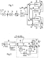
- signals arrive from an antenna 10 ⁇ via a preamplifier 12 and a mixer 14 to an analog IF filter 16.
- an analog IF filter At the output of the analog IF filter there is a frequency-modulated IF signal with a center frequency of 10 ⁇ , 7 MHz.
- This IF signal is sampled in a subsequent analog-digital converter 17 with the sampling frequency fA and converted into a digital signal.
- the digital signal is mixed into the complex baseband by sampling reduction and simultaneously subjected to digital filtering. The bandwidth is now around 30 ⁇ 0 ⁇ kHz.
- a digital phase response can be achieved by digital filtering.
- the digital complex baseband signal in the form a1 e i ⁇ 1 + a2 e i ⁇ 2 , with a1 the amplitude of the useful signal, a2 the amplitude of the interference signal, ⁇ 1 the phase of the useful signal and ⁇ 2 represent the phase of the interference signal.
- the circuit 20 ⁇ is matched to the carrier of the useful signal and the circuit 22 to the carrier of the interference signal, namely the adjacent channel.
- Demodulation of the baseband signals gives estimates for the phase ⁇ 1 of the useful signal at one output 24 of the circuit 20 ⁇ and estimates for the instantaneous amplitude a1 of the useful signal at the other output 26 of the circuit 20 ⁇ .
- estimates for the phase ⁇ 2 of the interference signal and 22 estimates for the instantaneous amplitude a2 of the interference signal can be tapped at an output 28 of the circuit 22 and at the other output 30 ⁇ of the circuit.
- the signal f 'detected by the digital PLL circuit, the instantaneous frequency is filtered by a simple low-pass filter 40 ⁇ and used to address the IF characteristic stored in a table of an addressable memory 42.
- the size obtained from the complete complex multiplication (t) with the reciprocal of the estimation signal formed in the circuit 44, ie the value 1 / â IF (t) at the Linkage point 46 is weighted, after which the size disturbed by incomplete compensation p (t) remains. This variable represents the amplitude fluctuation due to the attenuation in the transmission path.
- the following filter 48 can be designed to be narrowband.
- the signal â p (t) largely free of interference at the output of the filter 48 is now evaluated with the signal â ZF (t) at the junction 50stelle and the result of this evaluation supplies the estimated value of the instantaneous amplitude â (t).
- the signal for the phase present at the other output of the digital PLL is subject to less strong interferences than the amplitude, so that a simple filter 52 is sufficient to obtain an estimate signal for the phase from the demodulated input signal.
Landscapes
- Engineering & Computer Science (AREA)
- Power Engineering (AREA)
- Computer Networks & Wireless Communication (AREA)
- Signal Processing (AREA)
- Noise Elimination (AREA)
- Digital Transmission Methods That Use Modulated Carrier Waves (AREA)
Applications Claiming Priority (2)
| Application Number | Priority Date | Filing Date | Title |
|---|---|---|---|
| DE4110084 | 1991-03-27 | ||
| DE4110084A DE4110084A1 (de) | 1991-03-27 | 1991-03-27 | Verfahren zur nachbarkanalunterdrueckung beim empfang frequenzmodulierter sender |
Publications (3)
| Publication Number | Publication Date |
|---|---|
| EP0507139A2 true EP0507139A2 (fr) | 1992-10-07 |
| EP0507139A3 EP0507139A3 (en) | 1993-01-13 |
| EP0507139B1 EP0507139B1 (fr) | 1997-03-05 |
Family
ID=6428344
Family Applications (1)
| Application Number | Title | Priority Date | Filing Date |
|---|---|---|---|
| EP92104467A Expired - Lifetime EP0507139B1 (fr) | 1991-03-27 | 1992-03-16 | Procédé de suppression des signaux des canaux adjacents en réception FM |
Country Status (3)
| Country | Link |
|---|---|
| EP (1) | EP0507139B1 (fr) |
| JP (1) | JPH0590982A (fr) |
| DE (2) | DE4110084A1 (fr) |
Cited By (2)
| Publication number | Priority date | Publication date | Assignee | Title |
|---|---|---|---|---|
| EP0704982A3 (fr) * | 1994-09-30 | 1997-02-26 | At & T Corp | Récepteur radio pour traiter un signal à porteuses multiples ayant une large gamme dynamique |
| WO1999001945A1 (fr) * | 1997-06-19 | 1999-01-14 | Nokia Networks Oy | Procede de detection de signaux pour recepteur cellulaire numerique |
Family Cites Families (1)
| Publication number | Priority date | Publication date | Assignee | Title |
|---|---|---|---|---|
| DE3444449A1 (de) * | 1984-12-06 | 1986-06-12 | Robert Bosch Gmbh, 7000 Stuttgart | Demodulator fuer digitale empfaenger |
-
1991
- 1991-03-27 DE DE4110084A patent/DE4110084A1/de not_active Withdrawn
-
1992
- 1992-03-16 DE DE59208084T patent/DE59208084D1/de not_active Expired - Fee Related
- 1992-03-16 EP EP92104467A patent/EP0507139B1/fr not_active Expired - Lifetime
- 1992-03-27 JP JP4070917A patent/JPH0590982A/ja active Pending
Cited By (3)
| Publication number | Priority date | Publication date | Assignee | Title |
|---|---|---|---|---|
| EP0704982A3 (fr) * | 1994-09-30 | 1997-02-26 | At & T Corp | Récepteur radio pour traiter un signal à porteuses multiples ayant une large gamme dynamique |
| WO1999001945A1 (fr) * | 1997-06-19 | 1999-01-14 | Nokia Networks Oy | Procede de detection de signaux pour recepteur cellulaire numerique |
| AU741617B2 (en) * | 1997-06-19 | 2001-12-06 | Nokia Networks Oy | Signal detection method in a digital cellular receiver |
Also Published As
| Publication number | Publication date |
|---|---|
| EP0507139A3 (en) | 1993-01-13 |
| DE4110084A1 (de) | 1992-10-01 |
| JPH0590982A (ja) | 1993-04-09 |
| EP0507139B1 (fr) | 1997-03-05 |
| DE59208084D1 (de) | 1997-04-10 |
Similar Documents
| Publication | Publication Date | Title |
|---|---|---|
| EP0208982B1 (fr) | Filtre numérique de dérivation pour un récepteur de données | |
| DE3341430C2 (fr) | ||
| DE69703290T2 (de) | Als digitalsignalprozessor ausgeführter basisstationsempfänger für zellulares netzwerk | |
| DE69715069T2 (de) | Integrierter Empfänger | |
| DE60124234T2 (de) | Verfahren zur kompensation von phasenfehlern in mehrträgersignalen | |
| EP0558910B1 (fr) | Méthode d'élimination de bruits pour signaux stéréophoniques radiodiffusés | |
| DE69330554T2 (de) | Asynchrones modem für variable geschwindigkeiten | |
| DE4309518A1 (de) | Schaltungsanordnung zur Ableitung mindestens eines von der Qualität eines empfangenen Signals abhängigen Qualitätssignals | |
| DE2331146A1 (de) | Einseitenband-nachrichtenuebertragungseinrichtung | |
| EP1657917B1 (fr) | Procédé et montage de circuit pour le filtrage de canal de signaux TV à modulation analogique ou numérique | |
| DE4417723A1 (de) | Einrichtung zum Verarbeiten eines modulierten reellwertigen analogen Fernsehsignals | |
| EP0505867B1 (fr) | Procédé pour éliminer les signaux des canaux adjacents en réception FM | |
| EP0507139B1 (fr) | Procédé de suppression des signaux des canaux adjacents en réception FM | |
| WO1994022232A1 (fr) | Recepteur radio a traitement numerique de signaux | |
| DE2902616C3 (de) | UKW-Empfänger, insbesondere Autoempfänger, mit feldstärkeabhängiger Lautstärkesteuerung | |
| DE69937018T2 (de) | RDS Demodulator für den Empfang von Rundfunkprogrammen die Radiodatensignalen und Autofahrer Rundfunkinformationsignalen (ARI) enthalten, mit einer digitalen Filtervorrichtung die eine hohe Dämpfung des ARI Signals bewirkt | |
| DE1766434C3 (de) | Verfahren und Schaltungsanordnung zur Beseitigung von Störkomponenten beim Erfassen von Phasenschritten bei der Phasendemodulation | |
| EP0751654B1 (fr) | Synchronisation de trame, en particulier pour signaux à modulation multiporteuse | |
| DE2929679C2 (de) | UKW-Empfänger | |
| DE68926004T2 (de) | Übersprechstörung für übertragene Signale und Demodulation von Restseitenbandsignalen | |
| DE69027934T2 (de) | System mit kompaktem spektrum | |
| DE3843018A1 (de) | Schaltungsanordnung zur beseitigung von stoerungen | |
| DE3525172C2 (fr) | ||
| DE3245244C1 (de) | Methode zur simultanen Übertragung von binären Daten und Telefonsprechsignalen innerhalb des Sprachbandes eines Telefon-Übertragungskanals | |
| DE3246145A1 (de) | Fernsehuebertragungssystem mit integrierter uebertragung von zusatzinformationen, insbesondere tonsignalen |
Legal Events
| Date | Code | Title | Description |
|---|---|---|---|
| PUAI | Public reference made under article 153(3) epc to a published international application that has entered the european phase |
Free format text: ORIGINAL CODE: 0009012 |
|
| AK | Designated contracting states |
Kind code of ref document: A2 Designated state(s): DE FR IT PT |
|
| PUAL | Search report despatched |
Free format text: ORIGINAL CODE: 0009013 |
|
| AK | Designated contracting states |
Kind code of ref document: A3 Designated state(s): DE FR IT PT |
|
| 17P | Request for examination filed |
Effective date: 19930709 |
|
| 17Q | First examination report despatched |
Effective date: 19951215 |
|
| GRAG | Despatch of communication of intention to grant |
Free format text: ORIGINAL CODE: EPIDOS AGRA |
|
| GRAH | Despatch of communication of intention to grant a patent |
Free format text: ORIGINAL CODE: EPIDOS IGRA |
|
| GRAH | Despatch of communication of intention to grant a patent |
Free format text: ORIGINAL CODE: EPIDOS IGRA |
|
| GRAA | (expected) grant |
Free format text: ORIGINAL CODE: 0009210 |
|
| AK | Designated contracting states |
Kind code of ref document: B1 Designated state(s): DE FR IT PT |
|
| PGFP | Annual fee paid to national office [announced via postgrant information from national office to epo] |
Ref country code: FR Payment date: 19970319 Year of fee payment: 6 |
|
| REF | Corresponds to: |
Ref document number: 59208084 Country of ref document: DE Date of ref document: 19970410 |
|
| ET | Fr: translation filed | ||
| PGFP | Annual fee paid to national office [announced via postgrant information from national office to epo] |
Ref country code: DE Payment date: 19970517 Year of fee payment: 6 |
|
| ITF | It: translation for a ep patent filed | ||
| PLBE | No opposition filed within time limit |
Free format text: ORIGINAL CODE: 0009261 |
|
| STAA | Information on the status of an ep patent application or granted ep patent |
Free format text: STATUS: NO OPPOSITION FILED WITHIN TIME LIMIT |
|
| 26N | No opposition filed | ||
| PG25 | Lapsed in a contracting state [announced via postgrant information from national office to epo] |
Ref country code: FR Free format text: THE PATENT HAS BEEN ANNULLED BY A DECISION OF A NATIONAL AUTHORITY Effective date: 19980331 |
|
| PG25 | Lapsed in a contracting state [announced via postgrant information from national office to epo] |
Ref country code: PT Free format text: LAPSE BECAUSE OF NON-PAYMENT OF DUE FEES Effective date: 19980930 |
|
| PG25 | Lapsed in a contracting state [announced via postgrant information from national office to epo] |
Ref country code: DE Free format text: LAPSE BECAUSE OF NON-PAYMENT OF DUE FEES Effective date: 19981201 |
|
| REG | Reference to a national code |
Ref country code: FR Ref legal event code: ST |
|
| REG | Reference to a national code |
Ref country code: PT Ref legal event code: MM4A Free format text: LAPSE DUE TO NON-PAYMENT OF FEES Effective date: 19980930 |
|
| PG25 | Lapsed in a contracting state [announced via postgrant information from national office to epo] |
Ref country code: IT Free format text: LAPSE BECAUSE OF NON-PAYMENT OF DUE FEES;WARNING: LAPSES OF ITALIAN PATENTS WITH EFFECTIVE DATE BEFORE 2007 MAY HAVE OCCURRED AT ANY TIME BEFORE 2007. THE CORRECT EFFECTIVE DATE MAY BE DIFFERENT FROM THE ONE RECORDED. Effective date: 20050316 |
|
| PG25 | Lapsed in a contracting state [announced via postgrant information from national office to epo] |
Ref country code: PT Free format text: LAPSE BECAUSE OF NON-PAYMENT OF DUE FEES Effective date: 19970316 |