EP0507233A2 - Brûleur pour combustibles liquides - Google Patents
Brûleur pour combustibles liquides Download PDFInfo
- Publication number
- EP0507233A2 EP0507233A2 EP92105438A EP92105438A EP0507233A2 EP 0507233 A2 EP0507233 A2 EP 0507233A2 EP 92105438 A EP92105438 A EP 92105438A EP 92105438 A EP92105438 A EP 92105438A EP 0507233 A2 EP0507233 A2 EP 0507233A2
- Authority
- EP
- European Patent Office
- Prior art keywords
- fuel
- housing
- inner housing
- burner according
- combustion air
- Prior art date
- Legal status (The legal status is an assumption and is not a legal conclusion. Google has not performed a legal analysis and makes no representation as to the accuracy of the status listed.)
- Withdrawn
Links
Images
Classifications
-
- F—MECHANICAL ENGINEERING; LIGHTING; HEATING; WEAPONS; BLASTING
- F23—COMBUSTION APPARATUS; COMBUSTION PROCESSES
- F23C—METHODS OR APPARATUS FOR COMBUSTION USING FLUID FUEL OR SOLID FUEL SUSPENDED IN A CARRIER GAS OR AIR
- F23C7/00—Combustion apparatus characterised by arrangements for air supply
- F23C7/008—Flow control devices
-
- F—MECHANICAL ENGINEERING; LIGHTING; HEATING; WEAPONS; BLASTING
- F23—COMBUSTION APPARATUS; COMBUSTION PROCESSES
- F23C—METHODS OR APPARATUS FOR COMBUSTION USING FLUID FUEL OR SOLID FUEL SUSPENDED IN A CARRIER GAS OR AIR
- F23C7/00—Combustion apparatus characterised by arrangements for air supply
- F23C7/002—Combustion apparatus characterised by arrangements for air supply the air being submitted to a rotary or spinning motion
- F23C7/004—Combustion apparatus characterised by arrangements for air supply the air being submitted to a rotary or spinning motion using vanes
-
- F—MECHANICAL ENGINEERING; LIGHTING; HEATING; WEAPONS; BLASTING
- F23—COMBUSTION APPARATUS; COMBUSTION PROCESSES
- F23D—BURNERS
- F23D11/00—Burners using a direct spraying action of liquid droplets or vaporised liquid into the combustion space
- F23D11/24—Burners using a direct spraying action of liquid droplets or vaporised liquid into the combustion space by pressurisation of the fuel before a nozzle through which it is sprayed by a substantial pressure reduction into a space
- F23D11/26—Burners using a direct spraying action of liquid droplets or vaporised liquid into the combustion space by pressurisation of the fuel before a nozzle through which it is sprayed by a substantial pressure reduction into a space with provision for varying the rate at which the fuel is sprayed
Definitions
- the inventive solution is mainly achieved because the end of the ignition electrode is located at the point where a "rich” and thus easily flammable mixture is present, without the rest of the composition and operation of the fuel-air mixture needs to be changed.
- an adjustment head is fastened to the outer housing and slots are incorporated in the conical front part thereof.
- a sealing ring is arranged around the adjustable ring piston towards the adjustment head.
- the ring piston is preferably so long that it completely closes the slots in the advanced position and completely releases them in the retracted position.
- the air supply can be controlled by changing the adjustable ring piston.
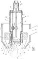
- FIG. 1 shows a longitudinal section through a heating oil burner, which is equipped with a conventional atomizing nozzle head 1.
- a conventional atomizing nozzle head Such conventional atomizing nozzle heads, which work under oil pressure, are for example the book by NIEPENBERG, industrial oil firing; Verlag Kopf, Stuttgart, 2nd edition, 1973.
- the nozzle head 1 forms the end of a fuel feed line 8.
- the fuel feed line 8 runs centrally within an inner housing 7.
- the inner housing 7 has a cylindrical wall which tapers in steps towards the front part of the burner.
- the fuel line 8 protruding from the inner housing 7 is supported in a support device 20.
- the oil supply can be switched on and off via a solenoid valve 18. Line 8 settles via the connection point A in the drawing in FIG. 2.
- an atomizing cone 16 is produced from the finest fuel particles with the nozzle head 1.
- the inner housing 7 ends in an opening 9.
- the inner housing carries, on its inside, already arranged in the outer edge of the spray cone 16, swirl generator 10, consisting of small, transverse guide surfaces, as can be seen in FIG.
- a nozzle 12 is provided for the supply of primary air. The primary air is guided inside the inner housing 7 into the area of the opening 9 and is brought into a vortex formation with the help of the swirl elements 10.
- a line 3.1 of an ignition electrode 3 is also held in the support device 20 and ends at an angle from the line 3.1 in front of the nozzle 1; with its other end, it projects like the fuel line 8 out of the inner housing 7 and is connected and connected in a known manner to a high-voltage source (not shown).
- the front part of the inner housing 7 encloses an outer housing 14 with a conical front part 14.1.
- an adjustment head 5 is fastened with a likewise conical front part 5.1. Secondary air is introduced into the outer housing 14 via a connector 15.
- Slots 19 are made in the conical front part 5.1.
- An adjustable, sliding ring piston 2 is fitted between the adjusting head 5 and the inner housing 7, which is sealed via a sealing ring 6 to the adjustment head 5.
- This annular piston 2 is so wide that it can both fully close and open the slots 19 so that the secondary air 15 can be introduced into the region of the vertebra 11 in an appropriately metered manner.
- the slots 19 can also be milled obliquely into the adjusting head 5, so that the air flow guided through the slots guides and reinforces the vortex 11 generated by the swirl devices 10.
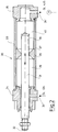
- the annular piston 2 is connected via a linkage 32 (shown schematically) to a rod piston 31 which belongs to a fuel valve 30 (cf. FIG. 2).
- the fuel valve 30 has a cylindrical housing 33 which is closed at its front end with a closure 34 and at its rear end with a closure 35. Both closures 34 and 35 are equipped via radial bores simultaneously as oil inlet 34 'and as oil outlet 35'.
- the inlet 34 ' is connected to a corresponding oil pressure line (not shown) and the oil outlet 35' is connected to the line 8 according to FIG. 1 (cf. connection point A).
- the housing 33 carries on its inside a projecting flange 36 which is toroidal and has the shape of an inwardly converging trapezoid in cross section.
- the flange touches with its inner surface 37 the outside of the rod piston 31.
- the wedge angle of the groove is approximately between 2 and 10 °.
- This groove 38 is in each case not closed by the flange 36 surrounding the piston rod 31, so that the oil under pressure in the corresponding position of the piston rod 31 can flow to a larger quantity per unit of time starting with the quantity zero, so that it flows from the space 39 in the space 40 within the cylindrical housing 33 and from there to the oil outlet 35 'can get.
- the stoichiometric amount of air supply required for the respective oil can be set precisely.
- the ignition electrode 3 and the fuel line 8 with the nozzle 1 can be adjusted relative to one another via the support device 20. Such an adjustment is normally not intended during operation. However, the adjustment option can be used, for example, if a certain ignition setting is required at the start of the burner setting or if the quality and composition or other parameters of the liquid fuel change.
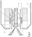
- FIG. 3 shows a front section of another heating oil burner with the same basic design.
- the fuel feed line 8 is adjustably arranged in an inner housing 7 via the support device 20.
- the ignition electrode 3 can also be adjusted.
- the nozzle 1 can thus be adjusted relative to the housing 7, the swirl generator 10 and the ignition electrode 3.
- the outer housing 14 is of a slightly different shape.
- the annular piston 2 can be moved together with the rod piston 31.
- the function of the device shown in Figures 1 and 3 is as follows:
- the fuel oil supply to the nozzle head 1 is controlled by the fuel feed line 8 via the valve 30.
- the supply air is controlled in accordance with the parameters and the conditions of the stoichiometry by adjusting the primary air and secondary air.
- the known nozzle 1 used is atomized an amount of heating oil dependent on the nozzle outlet pressure, which results in an atomizing cone 16 with an outer surface 17.
- a swirl generator 10 surrounds the nozzle head, which places the primary air in a vortex, which picks up the fine fuel oil droplets and guides them in a vortex. This vortex is further intensified with the additional smashing of the fuel oil droplets upon entry of the secondary air.
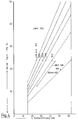
- the piston opening, ie adjustment of the piston 31 from a zero point, is indicated on the X axis.
- the quantity flowing through is directly proportional to the piston adjustment. While the upper curves show this relationship with a UMO 105 oil nozzle, the lower curves show the relationship with a UMO 108 nozzle
- Data in WS (mm water column) indicate the required air pressure.
Landscapes
- Engineering & Computer Science (AREA)
- Chemical & Material Sciences (AREA)
- Combustion & Propulsion (AREA)
- Mechanical Engineering (AREA)
- General Engineering & Computer Science (AREA)
- Pressure-Spray And Ultrasonic-Wave- Spray Burners (AREA)
Applications Claiming Priority (2)
| Application Number | Priority Date | Filing Date | Title |
|---|---|---|---|
| DE9103964U | 1991-04-02 | ||
| DE9103964U DE9103964U1 (de) | 1991-04-02 | 1991-04-02 | Brenner für flüssige Brennstoffe |
Publications (2)
| Publication Number | Publication Date |
|---|---|
| EP0507233A2 true EP0507233A2 (fr) | 1992-10-07 |
| EP0507233A3 EP0507233A3 (en) | 1993-02-24 |
Family
ID=6865881
Family Applications (1)
| Application Number | Title | Priority Date | Filing Date |
|---|---|---|---|
| EP19920105438 Withdrawn EP0507233A3 (en) | 1991-04-02 | 1992-03-30 | Burner for liquid fuels |
Country Status (2)
| Country | Link |
|---|---|
| EP (1) | EP0507233A3 (fr) |
| DE (1) | DE9103964U1 (fr) |
Cited By (14)
| Publication number | Priority date | Publication date | Assignee | Title |
|---|---|---|---|---|
| DE10164217A1 (de) * | 2001-12-31 | 2003-07-17 | Jochen Schanze | Brenner für eine Gebäudeheizanlage |
| US6866502B2 (en) | 2002-03-16 | 2005-03-15 | Exxonmobil Chemical Patents Inc. | Burner system employing flue gas recirculation |
| US6877980B2 (en) | 2002-03-16 | 2005-04-12 | Exxonmobil Chemical Patents Inc. | Burner with low NOx emissions |
| US6881053B2 (en) | 2002-03-16 | 2005-04-19 | Exxonmobil Chemical Patents Inc. | Burner with high capacity venturi |
| US6884062B2 (en) | 2002-03-16 | 2005-04-26 | Exxonmobil Chemical Patents Inc. | Burner design for achieving higher rates of flue gas recirculation |
| US6887068B2 (en) | 2002-03-16 | 2005-05-03 | Exxonmobil Chemical Patents Inc. | Centering plate for burner |
| US6890171B2 (en) | 2002-03-16 | 2005-05-10 | Exxonmobil Chemical Patents, Inc. | Apparatus for optimizing burner performance |
| US6890172B2 (en) | 2002-03-16 | 2005-05-10 | Exxonmobil Chemical Patents Inc. | Burner with flue gas recirculation |
| US6893251B2 (en) | 2002-03-16 | 2005-05-17 | Exxon Mobil Chemical Patents Inc. | Burner design for reduced NOx emissions |
| US6893252B2 (en) | 2002-03-16 | 2005-05-17 | Exxonmobil Chemical Patents Inc. | Fuel spud for high temperature burners |
| US6986658B2 (en) | 2002-03-16 | 2006-01-17 | Exxonmobil Chemical Patents, Inc. | Burner employing steam injection |
| WO2007051698A1 (fr) * | 2005-11-04 | 2007-05-10 | Alstom Technology Ltd | Lance de bruleur |
| US7322818B2 (en) | 2002-03-16 | 2008-01-29 | Exxonmobil Chemical Patents Inc. | Method for adjusting pre-mix burners to reduce NOx emissions |
| US7476099B2 (en) * | 2002-03-16 | 2009-01-13 | Exxonmobil Chemicals Patents Inc. | Removable light-off port plug for use in burners |
Family Cites Families (6)
| Publication number | Priority date | Publication date | Assignee | Title |
|---|---|---|---|---|
| US2976885A (en) * | 1955-07-08 | 1961-03-28 | Orr & Sembower Inc | Fuel control valves |
| FR1211598A (fr) * | 1957-08-27 | 1960-03-17 | Int Combustion Holdings Ltd | Installation de brûleurs pour combustibles liquides |
| NL224008A (fr) * | 1958-01-14 | 1960-11-15 | ||
| AT349595B (de) * | 1974-07-05 | 1979-04-10 | Olymp Heiz Service Gmbh | Einrichtung zur steuerung der oelzufuhr zu einem oelbrenner |
| DE2624649C3 (de) * | 1976-06-02 | 1980-05-08 | Danfoss A/S, Nordborg (Daenemark) | ölbrenner |
| DE2729321C2 (de) * | 1977-06-29 | 1983-10-20 | Smit Ovens Nijmegen B.V., Nijmegen | Verfahren zur Verbrennung von flüssigem Brennstoff sowie Brennereinrichtung zurDurchführung des Verfahrens |
-
1991
- 1991-04-02 DE DE9103964U patent/DE9103964U1/de not_active Expired - Lifetime
-
1992
- 1992-03-30 EP EP19920105438 patent/EP0507233A3/de not_active Withdrawn
Cited By (17)
| Publication number | Priority date | Publication date | Assignee | Title |
|---|---|---|---|---|
| DE10164217A1 (de) * | 2001-12-31 | 2003-07-17 | Jochen Schanze | Brenner für eine Gebäudeheizanlage |
| DE10164217B4 (de) * | 2001-12-31 | 2004-08-05 | Jochen Schanze | Brenner für eine Gebäudeheizanlage |
| US6890172B2 (en) | 2002-03-16 | 2005-05-10 | Exxonmobil Chemical Patents Inc. | Burner with flue gas recirculation |
| US6893251B2 (en) | 2002-03-16 | 2005-05-17 | Exxon Mobil Chemical Patents Inc. | Burner design for reduced NOx emissions |
| US6881053B2 (en) | 2002-03-16 | 2005-04-19 | Exxonmobil Chemical Patents Inc. | Burner with high capacity venturi |
| US6884062B2 (en) | 2002-03-16 | 2005-04-26 | Exxonmobil Chemical Patents Inc. | Burner design for achieving higher rates of flue gas recirculation |
| US6887068B2 (en) | 2002-03-16 | 2005-05-03 | Exxonmobil Chemical Patents Inc. | Centering plate for burner |
| US6890171B2 (en) | 2002-03-16 | 2005-05-10 | Exxonmobil Chemical Patents, Inc. | Apparatus for optimizing burner performance |
| US6866502B2 (en) | 2002-03-16 | 2005-03-15 | Exxonmobil Chemical Patents Inc. | Burner system employing flue gas recirculation |
| US6877980B2 (en) | 2002-03-16 | 2005-04-12 | Exxonmobil Chemical Patents Inc. | Burner with low NOx emissions |
| US6893252B2 (en) | 2002-03-16 | 2005-05-17 | Exxonmobil Chemical Patents Inc. | Fuel spud for high temperature burners |
| US6902390B2 (en) | 2002-03-16 | 2005-06-07 | Exxonmobil Chemical Patents, Inc. | Burner tip for pre-mix burners |
| US6986658B2 (en) | 2002-03-16 | 2006-01-17 | Exxonmobil Chemical Patents, Inc. | Burner employing steam injection |
| US7025587B2 (en) | 2002-03-16 | 2006-04-11 | Exxonmobil Chemical Patents Inc. | Burner with high capacity venturi |
| US7476099B2 (en) * | 2002-03-16 | 2009-01-13 | Exxonmobil Chemicals Patents Inc. | Removable light-off port plug for use in burners |
| US7322818B2 (en) | 2002-03-16 | 2008-01-29 | Exxonmobil Chemical Patents Inc. | Method for adjusting pre-mix burners to reduce NOx emissions |
| WO2007051698A1 (fr) * | 2005-11-04 | 2007-05-10 | Alstom Technology Ltd | Lance de bruleur |
Also Published As
| Publication number | Publication date |
|---|---|
| EP0507233A3 (en) | 1993-02-24 |
| DE9103964U1 (de) | 1992-07-30 |
Similar Documents
| Publication | Publication Date | Title |
|---|---|---|
| DE2731562C2 (de) | Brenner für flüssige und/oder gasförmige Brennstoffe | |
| EP0321809B1 (fr) | Procédé pour la combustion de combustible liquide dans un brûleur | |
| EP0507233A2 (fr) | Brûleur pour combustibles liquides | |
| DE2828826A1 (de) | Brenner fuer fluessigen brennstoff | |
| EP0636836A2 (fr) | Brûleur pour la combustion d'un combustible pulvérulent | |
| EP0902233A1 (fr) | Buse de pulvérisation par pression combinée | |
| DE2729321C2 (de) | Verfahren zur Verbrennung von flüssigem Brennstoff sowie Brennereinrichtung zurDurchführung des Verfahrens | |
| DE1992618U (de) | Gasbrenner. | |
| DE2806363C2 (de) | Verfahren zum Zünden der Verbrennung von Kohlenstaub | |
| DE2553953C2 (de) | Brenner für flüssige Brennstoffe | |
| EP0683883B1 (fr) | Bruleur a flamme bleue optimisant la combustion | |
| EP1030106B1 (fr) | Bruleur à flamme bleue optimisant la combustion | |
| DE2712564A1 (de) | Brenner fuer fluessige brennstoffe | |
| DE2345838A1 (de) | Brenner | |
| DE3718994C2 (fr) | ||
| WO1979000468A1 (fr) | Bruleur a mazout pour de faibles puissances de chauffage et procede de mise en action | |
| DE3424031A1 (de) | Verfahren zum verbrennen eines fluessigen oder festen, pulverfoermigen brennstoffes | |
| DE2820297A1 (de) | Geblaesebrenner und zusatzbrennerrohr fuer einen geblaesebrenner | |
| EP0683884B1 (fr) | Bruleur a flamme bleue ajustable | |
| DE2633634A1 (de) | Verfahren und vorrichtung zum zuenden einer flamme, die mit schwer entflammbarem fluessigen brennstoff gespeist wird | |
| DE4229525A1 (de) | Mischeinrichtung für Ölzerstäubungsbrenner | |
| DE19860785A1 (de) | Zerstäubungsvorrichtung | |
| DE2828319C2 (de) | Brenner für flüssigen Brennstoff mit einer zylindrischen Wirbelkammer | |
| DE3316323A1 (de) | Brenner, insbesondere gasbrenner fuer industrielle feuerungsanlagen, sowie brennerkopf hierfuer | |
| DE2835335A1 (de) | Brenner fuer durchlauferhitzer |
Legal Events
| Date | Code | Title | Description |
|---|---|---|---|
| PUAI | Public reference made under article 153(3) epc to a published international application that has entered the european phase |
Free format text: ORIGINAL CODE: 0009012 |
|
| AK | Designated contracting states |
Kind code of ref document: A2 Designated state(s): AT BE CH DE DK ES FR GB GR IT LI LU MC NL PT SE |
|
| PUAL | Search report despatched |
Free format text: ORIGINAL CODE: 0009013 |
|
| AK | Designated contracting states |
Kind code of ref document: A3 Designated state(s): AT BE CH DE DK ES FR GB GR IT LI LU MC NL PT SE |
|
| 17P | Request for examination filed |
Effective date: 19930824 |
|
| 17Q | First examination report despatched |
Effective date: 19941110 |
|
| STAA | Information on the status of an ep patent application or granted ep patent |
Free format text: STATUS: THE APPLICATION IS DEEMED TO BE WITHDRAWN |
|
| 18D | Application deemed to be withdrawn |
Effective date: 19951003 |