EP0507428A2 - Mehrweg-Übertragungssystem - Google Patents
Mehrweg-Übertragungssystem Download PDFInfo
- Publication number
- EP0507428A2 EP0507428A2 EP92300161A EP92300161A EP0507428A2 EP 0507428 A2 EP0507428 A2 EP 0507428A2 EP 92300161 A EP92300161 A EP 92300161A EP 92300161 A EP92300161 A EP 92300161A EP 0507428 A2 EP0507428 A2 EP 0507428A2
- Authority
- EP
- European Patent Office
- Prior art keywords
- multiplex
- troubleshooting
- nodes
- node
- transmission system
- Prior art date
- Legal status (The legal status is an assumption and is not a legal conclusion. Google has not performed a legal analysis and makes no representation as to the accuracy of the status listed.)
- Granted
Links
Images


Classifications
-
- H—ELECTRICITY
- H04—ELECTRIC COMMUNICATION TECHNIQUE
- H04L—TRANSMISSION OF DIGITAL INFORMATION, e.g. TELEGRAPHIC COMMUNICATION
- H04L12/00—Data switching networks
- H04L12/28—Data switching networks characterised by path configuration, e.g. LAN [Local Area Networks] or WAN [Wide Area Networks]
- H04L12/40—Bus networks
- H04L12/40169—Flexible bus arrangements
- H04L12/40176—Flexible bus arrangements involving redundancy
- H04L12/40182—Flexible bus arrangements involving redundancy by using a plurality of communication lines
-
- H—ELECTRICITY
- H04—ELECTRIC COMMUNICATION TECHNIQUE
- H04L—TRANSMISSION OF DIGITAL INFORMATION, e.g. TELEGRAPHIC COMMUNICATION
- H04L12/00—Data switching networks
- H04L12/28—Data switching networks characterised by path configuration, e.g. LAN [Local Area Networks] or WAN [Wide Area Networks]
- H04L12/40—Bus networks
- H04L12/407—Bus networks with decentralised control
- H04L12/413—Bus networks with decentralised control with random access, e.g. carrier-sense multiple-access with collision detection [CSMA-CD]
- H04L12/4135—Bus networks with decentralised control with random access, e.g. carrier-sense multiple-access with collision detection [CSMA-CD] using bit-wise arbitration
-
- B—PERFORMING OPERATIONS; TRANSPORTING
- B60—VEHICLES IN GENERAL
- B60R—VEHICLES, VEHICLE FITTINGS, OR VEHICLE PARTS, NOT OTHERWISE PROVIDED FOR
- B60R16/00—Electric or fluid circuits specially adapted for vehicles and not otherwise provided for; Arrangement of elements of electric or fluid circuits specially adapted for vehicles and not otherwise provided for
- B60R16/02—Electric or fluid circuits specially adapted for vehicles and not otherwise provided for; Arrangement of elements of electric or fluid circuits specially adapted for vehicles and not otherwise provided for electric constitutive elements
- B60R16/03—Electric or fluid circuits specially adapted for vehicles and not otherwise provided for; Arrangement of elements of electric or fluid circuits specially adapted for vehicles and not otherwise provided for electric constitutive elements for supply of electrical power to vehicle subsystems or for
- B60R16/0315—Electric or fluid circuits specially adapted for vehicles and not otherwise provided for; Arrangement of elements of electric or fluid circuits specially adapted for vehicles and not otherwise provided for electric constitutive elements for supply of electrical power to vehicle subsystems or for using multiplexing techniques
Definitions
- the present invention relates to a multipath transmission system for transferring signals between multiplex nodes connected to a plurality of networks, and more particularly, to a multipath transmission system for system troubleshooting.
- Some multipath transmission systems of this type are used in a system which includes two networks with different response characteristics (e.g., transmission speed).
- a plurality of multiplex nodes transmit signals, such as data, to each other through multiplex buses, thereby effecting independent control.
- One of the multiplex nodes constitutes an element common to both networks.
- This common node has a function as a gateway for relaying signals used in common in the two networks, as well as a communication facility for signal transmission.
- This multiplex node will hereinafter be referred to as gateway node.
- a specific multiplex node in each network periodically transmits signals to the network to which it belongs. This specific node checks reception response signals from the individual multiplex nodes. Alternatively, the specific multiplex node checks to see if the other multiplex nodes are normally operating by periodically transmitting signals to the nodes.
- the specific multiplex node In case of a failure in one of the multiplex nodes, the specific multiplex node infers an occurrence of some trouble from the absence of response signals, transmission failure, etc. if the defective node is in the same network as the specific multiplex node. If the defective node is in the other network to which the specific multiplex node does not belong, the specific node cannot detect it at all. In this multipath transmission system, the control method for each node must be changed, so that the other network should be informed of the details of the failure.
- the following is a description of the operation of the system which is supposed to be performed when a certain multiplex node in the first network is disabled from communication due to a failure.
- the specific multiplex node in the first network detects the disabled state of the defective multiplex node by periodic inspection, and then immediately transmits a signal indicative of the occurrence of the failure in the defective node to the first network.
- the gateway node On receiving this failure signal, the gateway node relays it to each multiplex node in the second network.
- the control method for each multiplex node in the second network can be also changed.
- the multiplex nodes in the first network can also utilize the failure signal, and the failure, having occurred in the same network, can be detected by any other suitable means.
- the operation of the system can be supposed to be performed in like manner when the defective multiplex node is in the second network. More specifically, in this case, the specific multiplex node in the second network detects the failure, and the gateway node relays a failure signal to the first network.
- the specific multiplex node comprises an emergency communication device and a troubleshooting device, and periodically checks to see if multiplex transmission lines (hereinafter referred to as multiplex buses) are normal.
- the emergency communication device can perform communication even if one wire of a twisted pair cable, which constitutes each transmission line, is shorted.
- the troubleshooting device can perform communication only when both wires of the cable are normal.
- the specific multiplex node finds, through the periodic inspection, a failure in the network to which it belongs, it turns on an alarm lamp in a meter, for example, thereby informing an operator of the failure.
- the specific multiplex node may be designed so that it can remember the occurrence of a failure if the failure is a relatively safe one, and can output failure record information when the system is inspected later in a repair shop or the like.
- the present invention has been contrived in consideration of these circumstances, and its object is to provide a multipath transmission system, capable of securely troubleshooting one network and securely relaying a failure signal to another network, thereby ensuring high-reliability multipath transmission.
- a multipath transmission system which comprises transmission lines constituting at least two networks, and a plurality of multiplex nodes connected to the transmission lines, each of the multiplex nodes including communication means for signal transmission through the transmission lines belonging to an identical network, at least one specific multiplex node, out of the plurality of multiplex nodes, including communication means connected to the two or more transmission lines and used for signal transfer between the transmission lines, and troubleshooting means for troubleshooting the connected transmission lines and the multiplex nodes connected to the transmission lines.
- the transmission lines constitute two or more networks, and each multiplex node is connected to one of the transmission lines to transmit signals through the same transmission line.
- the specific multiplex node which is connected to the transmission lines constituting a plurality of networks troubleshoots the transmission lines and the multiplex nodes, and transmits the result of troubleshooting, as required, to a network for the same or another line.
- the occurrence of a failure in one network can be securely detected, and the control method for each multiplex node can be properly changed, so that the reliability of the multipath transmission can be improved.
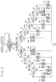
- a multipath transmission system which comprises networks 1 and 2 of two different systems.
- first network 1 multiplex nodes 11 to 15 and 20 transmit signals to each other through multiplex buses 3.
- second network 2 a plurality of multiplex nodes 16 to 20 transmit signals to one another through multiplex buses 4.
- These networks 1 and 2 are controlled independently of each other.
- a microprocessor (CPU) 21 for general process control is connected with two communication control circuits (LSI's) 22 and 23, which are each composed of a multipath transmission control IC for the control of transfer between the networks, buffers for transmission and reception, an interface, etc.
- a driver/receiver circuit (hereinafter referred to as D/R) 26 and a troubleshooting D/R 28 are connected to the LSI 22 through a switch 24.
- a D/R 27 and a troubleshooting D/R 29 are connected to the LSI 23 through a switch 25.
- the D/R's 26 and 27 are circuits for interfacing between the multiplex buses 3 and 4 and the LSI's 22 and 23, respectively.
- the D/R's 26 and 27 are designed so that communication can be secured even when the multiplex buses suffer a short-mode failure.
- the troubleshooting D/R's 28 and 29, like the D/R's 26 and 27, are circuits for interfacing between the multiplex buses 3 and 4 and the LSI's 22 and 23, respectively.
- the D/R's 28 and 29 are designed so that transmission or reception of signals to or from the individual multiplex nodes is allowed only when both wires of each multiplex bus, which is formed of a twisted pair cable, are normal.
- the CPU 21 sets the switches 24 and 25 so that the D/R's 26 and 27 are normally selected. Further, the CPU 21 periodically shifts the switches 24 and 25, and causes the troubleshooting D/R's 28 and 29 to check to see if the transmission and reception of signals are normally performed. If signals cannot be transferred between the troubleshooting D/R 28 or 29 and its corresponding network, the CPU 21 concludes that one of the twisted wires of the multiplex bus 3 or 4 is in trouble.
- the failure can be detected by means of a troubleshooting function based on the transmission and reception of signals, using the troubleshooting D/R's 28 and 29, even in case of disconnection of connectors, which connect the multiplex buses and the multiplex nodes, or a short circuit in the twisted pair cable, for example.
- the CPU 21 has a function to periodically monitor the operations of the networks 1 and 2, besides its original control function. More specifically, the multiplex node 20 periodically transmits signals to the networks 1 and 2, and checks reception response signals from the multiplex nodes to see if the individual multiplex nodes are normally operating. Alternatively, the multiplex node 20 checks to see if the multiplex nodes are normally operating by periodically transmitting specific signals to the individual nodes, for example.
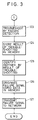
- Figs. 2 and 3 are flow charts for illustrating network troubleshooting operation performed by means of the gateway node 20.
- the LSI's 22 and 23 periodically receive response signals from all the multiplex nodes including the respective local stations of the two networks 1 and 2 in accordance with the operation control of the CPU 21. Then, the LSI's 22 and 23 cause reception buffers for the networks to store these reception signals as reception data from all the multiplex nodes.
- the CPU 21 fetches the reception data and determines whether or not the transmission of the reception signals from all the multiplex nodes is effected (Step 101). If any of the multiplex nodes transmits response signal, the CPU 21 identifies the network in which the response signal is not transmitted (Step 102).
- the CPU 21 discriminates the multiplex node which transmits no response signal, in accordance with the fetched response signal (Steps 103 to 107). This discrimination is made on the basis of ID data (data composed of addresses indicative of local stations, addresses indicative of destinations, data lengths, etc.) of the reception response signals. Based on the result of this discrimination, the CPU 21 identifies the multiplex node, among the multiplex nodes 11 to 15 and 20, from which the fetched reception response signal comes (Steps 108 to 113).
- ID data data composed of addresses indicative of local stations, addresses indicative of destinations, data lengths, etc.
- the CPU 21 discriminates the multiplex node which transmits no response signal, in accordance with the ID data of the fetched response signal (Steps 114 to 117), in the same manner as aforesaid. Based on the result of this discrimination, the CPU 21 identifies the multiplex node, among the multiplex nodes 16 to 20, from which the fetched reception response signal comes (Steps 118 to 122).
- the CPU 21 identifies the multiplex node which transmits no response signal in Steps 108 to 113 and Steps 118 to 122, whereupon it troubleshoots in response to a detection of failure (Step 123). Then, the CPU 21 writes and stores the result of this troubleshooting in its internal memory, as a failure history of the multiplex node concerned (Step 124). In response to the result of this troubleshooting, moreover, the CPU 21 discriminates the multiplex node which requires a failure signal (Step 125). Using the troubleshooting result data stored in the internal memory, furthermore, the CPU 21 produces a failure signal which is composed of ID data and data corresponding to the result of the troubleshooting. Then, the failure signal is written in the respective network transmission buffers of the LSI's 22 and 23 (Step 126).
- the LSI's 22 and 23 transmit the signal in the buffers to the multiplex nodes (all the multiplex nodes except the one in trouble) of the networks 1 and 2 which require this failure signal, in accordance with the ID data (Step 127).
- This transmission of the failure signal may be executed for the other network after being executed for the one in trouble. Since each multiplex node can independently detect failure in its corresponding network, the failure signal may be transmitted only to the network which is not in trouble.
- the CPU 21 terminates this process operation.
- the node 20 can detect the failure in the communication function of its own local station by periodic inspection, as in the case of failure in any other multiplex node, and immediately transmit a failure signal to the network 2.
- Fig. 4 is a block diagram showing a specific layout of the multipath transmission system of Fig. 1 incorporated in an automobile.
- numerals 5, 6 and 7 denote an engine compartment, a driver's cab, and a trunk compartment, respectively, which are divided from one another by dashed lines.
- the multiplex buses 3a to 3d and 4a to 4c which are each formed of a twisted pair cable or the like, are connected to one another by means of connectors C1 to C8, and are arranged in two loops for balanced signal transmission.
- the multiplex bus 3a which is incorporated in a wire harness which passes through, for example, the dashboard in the driver's cab 6, is connected with the multiplex nodes 11, 12 and 20 which are control units with a communication function.
- the multiplex bus 3b which is incorporated in a wire harness which passes through, for example, the instrument panel, is connected with the multiplex nodes 13 and 14 which also have a communication function.
- the multiplex bus 3c which is incorporated in a wire harness which passes through, for example, a floor portion beside the seats, is connected with the multiplex node 15 which also has a communication function.
- the multiplex bus 3d is incorporated in a wire harness which passes through, for example, a floor portion beside the seats and the floor of the trunk compartment 7.
- the multiplex nodes 11 to 15 and 20 and the multiplex buses 3a to 3d constitute the first network.
- the multiplex nodes 11 to 15 and 20 have the same response characteristic, and signals can be transferred at least between them by communication through the multiplex buses 3a to 3d.
- the multiplex bus 4a which is incorporated in a wire harness which passes through, for example, the dashboard, is connected with the multiplex nodes 16 to 18 and 20 which also have a communication function.
- the multiplex bus 4c which is incorporated in a wire harness which passes through, for example, a floor portion beside the seats and the floor of the trunk compartment 7, is connected with the multiplex node 19 which also has a communication function.
- the multiplex nodes 16 to 20 and the multiplex buses 4a to 4c constitute the second network.
- the multiplex nodes 16 to 20 have the same response characteristic (different from that of the multiplex nodes 11 to 15), and signals can be transferred at least between them by communication through the multiplex buses 4a to 4c.
- the first network for example, is used for the transmission of signals from switches operated by a driver, control signals for actuators produced in response to the switch signals, and the like.
- the second network for example, is used for the transfer of signals at least between various multiplex nodes, such as the engine, transmission gear, suspension system, braking system, etc., which requires a relatively high reliability.
- the system thus furnished with the networks of the two types requires troubleshooting faculty and a measure to counter failure in the multiplex nodes or multiplex buses. Since the transfer of the signals associated with the control of the engine, braking system, etc. requires high reliability, moreover, a higher-performance troubleshooting function is essential to the system. According to a method of fulfilling the troubleshooting function, for example, the driver is warned of a failure when it is detected, and the control of the engine, braking system, etc. is switched to an emergency control mode in which no networks are used.
- the gateway node 20 is a control unit connected to or contained in a joint box which is located beside the instrument panel.
- the joint box is connected with a plurality of wire harnesses which are arranged in the vehicle.
- the joint box is connected with the respective end portions of the wire harness in the dashboard, in which the multiplex buses 3b and 4a are incorporated, the wire harness in the instrument panel, in which the multiplex bus 3a is incorporated, and the wire harness connected to electric apparatuses in the engine compartment 5, as indicated by broken line in Fig. 4.
- Signal lines (including multiplex buses) in the connected wire harnesses are connected to branch circuits, which are formed of bus bars in the joint box, and are branched off to the multiplex node 20 which is contained in (or connected to) the joint box. Some of the signal lines, which need not be branched off, are connected directly to the multiplex node 20 without using the bus bars.
- Power lines in the connected wire harnesses are arranged in the same manner as the signal lines. Some of the power lines are protected against a short circuit or other failure by means of fuses in the joint box.
- Switching elements are also mounted in the joint box or the multiplex node 20, and the respective circuits of some of the electric apparatuses are switched by means of these switching elements.
- the multiplex node 20 which can receive signals from the wire harnesses or through the multiplex buses, serves to drive the electric apparatuses by controlling the switching elements in accordance with the signals and to transmit the signals to the other multiplex nodes through the multiplex buses.
- This network troubleshooting function is given to the multiplex node 20 contained in (or connected to) the joint box because the joint box is connected with many wire harnesses for various functions, such as protection of the power source, distribution of power and signals, etc. Another reason is that many of those wire harnesses which cannot be connected directly to the joint box are connected to the wire harnesses which are connected directly to the joint box in close vicinity thereto. In the example shown in Fig. 4, these wire harnesses correspond to the ones which incorporate the multiplex buses 3c and 4b and pass through the floor portion beside the driver's seat. These wire harnesses cannot be connected directly to the joint box which contains the multiplex node 20. In the region very close to the joint box, however, these wire harnesses are connected individually to wire harnesses, which incorporate the multiplex buses 3a and 4a, by means of connectors C3 and C6.
- the wire harnesses which incorporate the multiplex buses of the networks are connected directly to or arranged very close to the multiplex node 20. Therefore, the multiplex node 20 can be efficiently provided with a function to relay signals of the networks by only connecting the multiplex buses incorporated in those wire harnesses which are already connected to or arranged in close vicinity to the node 20.
- the multiplex node 20 can be regarded as an optimum node for the relaying function, and therefore, as a multiplex node for the troubleshooting function for both networks.
- the multiplex node having the gateway function is provided with the troubleshooting function, so that a failure signal can be transmitted to the normal network in case of failure. Accordingly, the control method for each multiplex node can be properly changed.
- the gateway node can grasp all the transmission and reception signals in the data transmission system, and directly obtain the data transmitted through the multiplex buses. Accordingly, the necessary failure signal can be securely relayed to the other network by giving the troubleshooting function to the gateway node. Thus, extra failure information cannot be transmitted, and the system can be totally troubleshooted.
- part of an algorithm for troubleshooting can be used in common by concentrating the troubleshooting function on the one gateway node, so that the total load on the multiplex nodes can be reduced.
- the multipath transmission system of the present invention high-reliability multipath transmission can be effected, so that the efficiency of data transmission can be improved.
Landscapes
- Engineering & Computer Science (AREA)
- Computer Networks & Wireless Communication (AREA)
- Signal Processing (AREA)
- Small-Scale Networks (AREA)
- Dc Digital Transmission (AREA)
Applications Claiming Priority (2)
| Application Number | Priority Date | Filing Date | Title |
|---|---|---|---|
| JP70028/91 | 1991-04-02 | ||
| JP3070028A JPH04339437A (ja) | 1990-07-09 | 1991-04-02 | 多重伝送方式の診断装置及び多重伝送システム |
Publications (3)
| Publication Number | Publication Date |
|---|---|
| EP0507428A2 true EP0507428A2 (de) | 1992-10-07 |
| EP0507428A3 EP0507428A3 (de) | 1992-11-25 |
| EP0507428B1 EP0507428B1 (de) | 1997-04-02 |
Family
ID=13419735
Family Applications (1)
| Application Number | Title | Priority Date | Filing Date |
|---|---|---|---|
| EP92300161A Expired - Lifetime EP0507428B1 (de) | 1991-04-02 | 1992-01-08 | Mehrweg-Übertragungssystem |
Country Status (3)
| Country | Link |
|---|---|
| US (1) | US5307340A (de) |
| EP (1) | EP0507428B1 (de) |
| DE (1) | DE69218653T2 (de) |
Cited By (6)
| Publication number | Priority date | Publication date | Assignee | Title |
|---|---|---|---|---|
| EP0915599A3 (de) * | 1997-11-06 | 1999-12-01 | Robert Bosch Gmbh | Anschlussvorrichtung zum Ankoppeln mindestens zweier Bussysteme |
| WO1999063212A1 (en) * | 1998-06-02 | 1999-12-09 | Pratt & Whitney Canada Corp | Exciter controlled by full authority digital electronic control (fadec) system |
| EP0911221A3 (de) * | 1997-10-27 | 2000-10-04 | Harness System Technologies Research, Ltd. | Im Kraftfahrzeug eingebautes Multiplexübertragungssystem |
| WO2002080463A1 (de) * | 2001-03-29 | 2002-10-10 | Robert Bosch Gmbh | Busmaster für einen bus zum anschluss von sensoren und/oder zündmitteln |
| CN101462518B (zh) * | 2007-12-17 | 2011-01-12 | 株式会社日立制作所 | 车载电子系统以及汽车 |
| WO2012105947A1 (en) * | 2011-01-31 | 2012-08-09 | Hewlett-Packard Development Company, L.P. | Cable harness switches |
Families Citing this family (7)
| Publication number | Priority date | Publication date | Assignee | Title |
|---|---|---|---|---|
| JP3123629B2 (ja) * | 1993-09-16 | 2001-01-15 | 富士電機株式会社 | 信号伝送用lsi |
| US6351768B1 (en) * | 1997-12-19 | 2002-02-26 | At&T Corp | Performance monitor for leased transmission facilities |
| DE10026124A1 (de) * | 2000-05-26 | 2001-11-29 | Bayerische Motoren Werke Ag | Schaltungsanordnung für ein Kraftfahrzeug |
| US7092361B2 (en) * | 2001-12-17 | 2006-08-15 | Alcatel Canada Inc. | System and method for transmission of operations, administration and maintenance packets between ATM and switching networks upon failures |
| US7069245B2 (en) * | 2003-02-06 | 2006-06-27 | Business Wire | Simultaneous network news distribution |
| US7369571B2 (en) * | 2004-04-30 | 2008-05-06 | Ericsson Ab | Method and system for sending E-LSP packets having QoS across a cell ATM based network |
| US20150341204A1 (en) * | 2013-03-11 | 2015-11-26 | Mitsubishi Electric Corporation | Train-informati0n management device |
Family Cites Families (9)
| Publication number | Priority date | Publication date | Assignee | Title |
|---|---|---|---|---|
| US4747097A (en) * | 1985-03-12 | 1988-05-24 | Oki Electric Industry Co., Ltd. | Multiplex transmission system |
| JPS6256032A (ja) * | 1985-09-04 | 1987-03-11 | Nissan Motor Co Ltd | 車両用通信装置 |
| DE3534216A1 (de) * | 1985-09-25 | 1987-04-02 | Bayerische Motoren Werke Ag | Datenbussystem fuer fahrzeuge |
| US4841520A (en) * | 1986-10-21 | 1989-06-20 | Amp Incorporated | Data transmission system with bus failure detection system |
| JPS6460026A (en) * | 1987-08-31 | 1989-03-07 | Fujitsu Ltd | Transmission line switching device for communication equipment |
| DE3810367A1 (de) * | 1988-03-26 | 1989-10-05 | Telefonbau & Normalzeit Gmbh | Verfahren zur erhoehung der betriebssicherheit von zur informationsuebertragung eingesetzten bussystemen in kommunikations-vermittlungsanlagen |
| JPH02182057A (ja) * | 1989-01-09 | 1990-07-16 | Canon Inc | ネツトワーク管理方式 |
| JP2904283B2 (ja) * | 1989-05-22 | 1999-06-14 | マツダ株式会社 | 車両用多重伝送装置 |
| JP2904296B2 (ja) * | 1990-03-30 | 1999-06-14 | マツダ株式会社 | 車両用多重伝送装置 |
-
1991
- 1991-12-30 US US07/815,922 patent/US5307340A/en not_active Expired - Lifetime
-
1992
- 1992-01-08 EP EP92300161A patent/EP0507428B1/de not_active Expired - Lifetime
- 1992-01-08 DE DE69218653T patent/DE69218653T2/de not_active Expired - Fee Related
Cited By (8)
| Publication number | Priority date | Publication date | Assignee | Title |
|---|---|---|---|---|
| EP0911221A3 (de) * | 1997-10-27 | 2000-10-04 | Harness System Technologies Research, Ltd. | Im Kraftfahrzeug eingebautes Multiplexübertragungssystem |
| EP0915599A3 (de) * | 1997-11-06 | 1999-12-01 | Robert Bosch Gmbh | Anschlussvorrichtung zum Ankoppeln mindestens zweier Bussysteme |
| WO1999063212A1 (en) * | 1998-06-02 | 1999-12-09 | Pratt & Whitney Canada Corp | Exciter controlled by full authority digital electronic control (fadec) system |
| US6195247B1 (en) | 1998-06-02 | 2001-02-27 | Pratt & Whitney Canada | Exciter controlled by FADEC system |
| WO2002080463A1 (de) * | 2001-03-29 | 2002-10-10 | Robert Bosch Gmbh | Busmaster für einen bus zum anschluss von sensoren und/oder zündmitteln |
| US7400641B2 (en) | 2001-03-29 | 2008-07-15 | Robert Bosch Gmbh | Bus master for a bus for connection of sensors and/or ignition means |
| CN101462518B (zh) * | 2007-12-17 | 2011-01-12 | 株式会社日立制作所 | 车载电子系统以及汽车 |
| WO2012105947A1 (en) * | 2011-01-31 | 2012-08-09 | Hewlett-Packard Development Company, L.P. | Cable harness switches |
Also Published As
| Publication number | Publication date |
|---|---|
| EP0507428A3 (de) | 1992-11-25 |
| EP0507428B1 (de) | 1997-04-02 |
| DE69218653T2 (de) | 1997-11-06 |
| US5307340A (en) | 1994-04-26 |
| DE69218653D1 (de) | 1997-05-07 |
Similar Documents
| Publication | Publication Date | Title |
|---|---|---|
| CN113271242B (zh) | 通信系统 | |
| US6151298A (en) | Electronic bus system | |
| EP0946917B1 (de) | Elektronisches bussystem | |
| US5307340A (en) | Multipath transmission system with a troubleshooting arrangement for detecting failure | |
| US4739183A (en) | Local area network for vehicle | |
| EP0529650B1 (de) | Kraftfahrzeug-Multiplexübertragungsgerät | |
| JPH07507909A (ja) | 自動車用通信システム | |
| JPH02266628A (ja) | 通信回路網 | |
| US9065676B2 (en) | Communication circuit, relay connecting circuit, and communication network | |
| US5079759A (en) | Multiplex transmission system for vehicles having a failure diagnosis function | |
| EP0467512A2 (de) | Kommunikationssystem für Kraftfahrzeuge | |
| US6404326B1 (en) | Redundant power communications circuit | |
| US7260325B2 (en) | Network component for an optical network comprising an emergency operation function, especially for an optical network in ring topology | |
| JPH08186880A (ja) | 車載多重伝送システム | |
| US11516047B2 (en) | Communication system | |
| EP2061206B1 (de) | Elektronische Steuereinheit, Kommunikationssystem und Verfahren | |
| EP1359057B1 (de) | Datenübertragungssystem im Fahrzeug mit redundanten Verbindungen | |
| CA2025173C (en) | Diagnostic apparatus for a vehicle network system and method of diagnosing a vehicle network system | |
| EP1356352B1 (de) | Steueranordnung auf der basis von can-bus-technologie | |
| JPH04339437A (ja) | 多重伝送方式の診断装置及び多重伝送システム | |
| JP2010206651A (ja) | 通信中継装置、通信中継方法、通信ネットワークおよび電子制御装置 | |
| JP3050961B2 (ja) | ネットワークシステムの故障診断方法 | |
| US12483438B2 (en) | Vehicular multiplex bus system with backup powerline communication | |
| US20050157710A1 (en) | Data bus system | |
| JP2002314554A (ja) | 車両用通信装置 |
Legal Events
| Date | Code | Title | Description |
|---|---|---|---|
| PUAI | Public reference made under article 153(3) epc to a published international application that has entered the european phase |
Free format text: ORIGINAL CODE: 0009012 |
|
| AK | Designated contracting states |
Kind code of ref document: A2 Designated state(s): DE FR GB |
|
| PUAL | Search report despatched |
Free format text: ORIGINAL CODE: 0009013 |
|
| AK | Designated contracting states |
Kind code of ref document: A3 Designated state(s): DE FR GB |
|
| 17P | Request for examination filed |
Effective date: 19930517 |
|
| 17Q | First examination report despatched |
Effective date: 19950810 |
|
| GRAG | Despatch of communication of intention to grant |
Free format text: ORIGINAL CODE: EPIDOS AGRA |
|
| GRAH | Despatch of communication of intention to grant a patent |
Free format text: ORIGINAL CODE: EPIDOS IGRA |
|
| GRAH | Despatch of communication of intention to grant a patent |
Free format text: ORIGINAL CODE: EPIDOS IGRA |
|
| GRAA | (expected) grant |
Free format text: ORIGINAL CODE: 0009210 |
|
| AK | Designated contracting states |
Kind code of ref document: B1 Designated state(s): DE FR GB |
|
| REF | Corresponds to: |
Ref document number: 69218653 Country of ref document: DE Date of ref document: 19970507 |
|
| ET | Fr: translation filed | ||
| PLBE | No opposition filed within time limit |
Free format text: ORIGINAL CODE: 0009261 |
|
| 26N | No opposition filed | ||
| PGFP | Annual fee paid to national office [announced via postgrant information from national office to epo] |
Ref country code: GB Payment date: 20000105 Year of fee payment: 9 |
|
| PGFP | Annual fee paid to national office [announced via postgrant information from national office to epo] |
Ref country code: FR Payment date: 20000112 Year of fee payment: 9 |
|
| PG25 | Lapsed in a contracting state [announced via postgrant information from national office to epo] |
Ref country code: GB Free format text: LAPSE BECAUSE OF NON-PAYMENT OF DUE FEES Effective date: 20010108 |
|
| GBPC | Gb: european patent ceased through non-payment of renewal fee |
Effective date: 20010108 |
|
| PG25 | Lapsed in a contracting state [announced via postgrant information from national office to epo] |
Ref country code: FR Free format text: LAPSE BECAUSE OF NON-PAYMENT OF DUE FEES Effective date: 20010928 |
|
| REG | Reference to a national code |
Ref country code: FR Ref legal event code: ST |
|
| PGFP | Annual fee paid to national office [announced via postgrant information from national office to epo] |
Ref country code: DE Payment date: 20080104 Year of fee payment: 17 |
|
| PG25 | Lapsed in a contracting state [announced via postgrant information from national office to epo] |
Ref country code: DE Free format text: LAPSE BECAUSE OF NON-PAYMENT OF DUE FEES Effective date: 20090801 |