EP0507715A1 - Optisches Verbindungssystem mit Modul-Paaren - Google Patents
Optisches Verbindungssystem mit Modul-Paaren Download PDFInfo
- Publication number
- EP0507715A1 EP0507715A1 EP92460010A EP92460010A EP0507715A1 EP 0507715 A1 EP0507715 A1 EP 0507715A1 EP 92460010 A EP92460010 A EP 92460010A EP 92460010 A EP92460010 A EP 92460010A EP 0507715 A1 EP0507715 A1 EP 0507715A1
- Authority
- EP
- European Patent Office
- Prior art keywords
- input
- module
- output port
- output
- computer system
- Prior art date
- Legal status (The legal status is an assumption and is not a legal conclusion. Google has not performed a legal analysis and makes no representation as to the accuracy of the status listed.)
- Withdrawn
Links
Images
Classifications
-
- H—ELECTRICITY
- H04—ELECTRIC COMMUNICATION TECHNIQUE
- H04B—TRANSMISSION
- H04B10/00—Transmission systems employing electromagnetic waves other than radio-waves, e.g. infrared, visible or ultraviolet light, or employing corpuscular radiation, e.g. quantum communication
- H04B10/11—Arrangements specific to free-space transmission, i.e. transmission through air or vacuum
- H04B10/114—Indoor or close-range type systems
- H04B10/1143—Bidirectional transmission
Definitions
- the present invention relates to an optical link system by paired modules ensuring data transmission between a computer system, such as a microcomputer, minicomputer or computer and at least one prewired computer network or another computer system or device.
- peripheral such as a modem, printer, etc.
- the present invention proposes to solve these various problems.
- a first computer system is connected to a connection socket of a computer network, to a second computer system or to a peripheral device by means of an optical link consisting, on the side of the first computer system, of a first optical transmission unit consisting of at least one optical transmission module and, on the side of the connection socket, of the second computer system or of the peripheral device, of a second optical transmission unit consisting of at least one transmission module, a module of the first unit being paired one to one with a module of the second unit, each module consisting of an input-output port connected, for each module of the first unit, to a corresponding input-output port of the first computer system and, for each module of the second unit, to the connection socket of said network or to a corresponding input-output port of the second system computer or peripheral device, a light emitter connected to the data lines of said input-output port and a light detector connected to the data lines of said input-output port, the emitter emitting a radiation having a given wavelength assigned to the module concerned and an optical link consist
- the detector is connected to the input-output port via a demodulator.
- said demodulator is a comparator which compares the signals delivered by the detector to a predetermined threshold value.
- the input-output port is of the serial data transmission type and the transmitter and the detector are connected to the data line of said port.
- the input-output port is of the serial data transmission type and the transmitter and the output of said demodulator are connected to the data line of said port.
- the input-output port is of the type with parallel data transmission, the transmitter being connected to the output of a parallel / serial converter whose input is connected to the lines of module input-output port data and the detector being connected to the input of a serial / parallel converter whose output is connected to the data lines of the module input-output port.
- the input-output port is of the type with parallel data transmission, the transmitter being connected to the output of a parallel / serial converter whose input is connected to the data lines. from the module's input-output port and the output of the demodulator being connected to the input of a serial / parallel converter whose output is connected to the data lines of the module's input-output port.
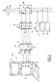
- a computer system 10 which consists, for example, of a microcomputer comprising a keyboard 11 and a screen 12 respectively connected to a central unit 13. It could also be a computer, '' a mini-computer or any other computer processing system.
- the central unit 13 is provided with three input-output ports 131, 132, 133 which are, for example, respectively for data transmission according to a first mode, a second mode and a third mode . Note that these three modes are not necessarily different.
- each port input-output 131, 132, 133 can, depending on the transmission mode it supports, be of the "RS 232", “IEEE 488", “TOKEN RING” R , “ETHERNET” R , "ISDN” type, etc.
- the first type of port 131 is connected to the input-output port 210 of a first transmission module 21 of a first type.
- the second type port 132 is connected to the input-output port 220 of a second transmission module 22 of a second type.
- the modules 21, 22, 23 together form an optical transmission unit 20.
- Fig. 1 we also see a set of lines 31, 32, 33 forming the wired support 30 of a computer network.
- the signals circulate according to the first mode of transmission of port 131; on line 32, they circulate according to the second mode of transmission of port 132 and, on line 33, they circulate according to the third mode of port 133.
- peripheral devices such as a modem 40 connected, on the one hand, to a telephone line T and, on the other hand, to line 31, a printer 50 having its input-output port which is connected to line 32 and a computer system 60 connected at line 33.
- a transmission unit 70 consists of three transmission modules 71, 72 and 73, respectively of the first, second and third type. They have their input-output ports 710, 720 and 730 which are respectively connected to the three connection pads 81, 82 and 83 of a connection socket 80 of the network 30. The pads 81, 82 and 83 are respectively connected to the lines 31, 32 and 33.
- a network 30 has been described to which are connected, on the one hand, peripheral devices and, on the other hand, a computer system 10. Nevertheless, the invention also applies to the case where the peripheral devices 40, 50 and 60 are connected to the system 10. In this case, the modules 71, 72, 73 are directly connected to the devices 40, 50 and 60.
- Each module 21, 22, 23, 71, 72, 73 can emit and detect radiation from a domain of given wavelengths depending on the mode of transmission involved in the link it provides.
- the modules 21, 22, 23 are respectively biunivocally paired with the modules 71, 72, 73.
- the differentiation between the optical signals emitted by the different modules ensuring the same optical link is made in wavelength.
- first type modules such as those referenced 21 and 71, only emit radiation of a first wavelength, for example in red, and are only sensitive to these radiations
- the modules of the second type such as those referenced 22 and 72
- the modules of the third type such that those referenced 23 and 73 emit only radiation of a third wavelength, for example in blue, and are only sensitive to these radiations.
- the modules 21 to 23 and 71 to 73 have the same constitution.
- the computer system 10 controls the printing of a document, it establishes a link between its input-output port 132 and the printer 50 via the optical link produced by the paired modules 22 and 72 .
- it if it must transmit or receive data from the modem 50, it establishes an optical link between its input-output port 131 and the modem 50 via the paired modules 21 and 71.
- it in order to have access to the computer system 60, it establishes an optical link from its input-output port 133 via the modules 23 and 73.
- Optical links have been described using three pairs of modules of different types, but it is obvious that a different number of links could be established with a corresponding number of pairs of modules of different types or not, as required. If several modules of the same type are used, their transmission wavelengths must be provided for different.
- the invention is not limited to the wavelengths corresponding to the colors mentioned above, or even to those of the visible range.
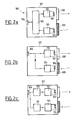
- a module 100 comprises an amplifier 101, the output of which is connected to a light emitter 102 of a given wavelength.
- the transmitter 102 is, for example, a light emitting diode or a laser type diode.
- the transmitter 102 also includes a demodulator 103, the input of which is connected to a light detector 104, for example a photodiode or a phototransistor.
- the output of the demodulator 103 is connected to an input of a control unit 105, one output of which is connected to the input of the amplifier 101.
- the unit 105 comprises an input-output port connected to the input port -output 106 of module 100.
- the demodulator 103 is advantageously a comparator which compares the signals delivered to it by the detector with a predetermined threshold value. It makes it possible to detect incident radiation which is insensitive to ambient radiation.
- windows 108 and 109 are provided for carrying out optical communication between the interior and the exterior of the case 107.
- the window 108 is located opposite the transmitter 102 and is advantageously transparent while the window 109 is located opposite the detector 104 and consists of an optical color filter allowing the only radiation to pass through a wavelength domain including the wavelength emitted by the transmitter 102.
- the transmitter 102 has a transmission cone with an angle greater than 10 °, which allows relative movement between the modules of the unit 20 and those of the unit 70.
- the control unit 105 is provided to allow the exchange of data between the input-output port 106 of the module and the amplifier 101 as well as between the demodulator 103 and the input-output port 106.
- data when data is sent to port 106, it is transmitted to the amplifier 101 which then controls the transmitter 102 so that it transmits a modulated optical signal.
- a modulated radiation When a modulated radiation is received by the module, it is first filtered by the optical filter 109. If the wavelength of this radiation does not correspond to the wavelength of the emitter 102, the detector 104 does not receive it and consequently does not deliver signals to the demodulator 103. On the other hand, if it corresponds to that of transmission from the transmitter 102, the detector 104 detects it and transforms the optical signals into electrical signals. These are transmitted to the demodulator 103. The latter compares, for example, these electrical signals to a threshold value and then delivers a demodulated signal which is transmitted to the control unit 105. The latter transmits the data received on the input-
- FIG. 2b There is shown in Figs. 2b and 2c, embodiments of particular modules.
- the module of FIG. 2b is designed to receive, on its input-output port 106, the data signals in serial form.
- Port 106 is, for example, of the "RS 232" type.
- the input of amplifier 101 and the output of demodulator 103 are directly connected to the data line of port 106.
- the module of FIG. 2c is provided with an input-output port 106 of the parallel type, for example "IEEE 488".
- the amplifier 101 receives the signals from a parallel / serial converter 110 whose input is connected to the data lines of the port 106.
- a serial / parallel converter 111 has its input connected to the output of the demodulator 103 and to its output directly connected to the data lines of the port of module 106.
Landscapes
- Physics & Mathematics (AREA)
- Electromagnetism (AREA)
- Engineering & Computer Science (AREA)
- Computer Networks & Wireless Communication (AREA)
- Signal Processing (AREA)
- Communication Control (AREA)
- Computer And Data Communications (AREA)
Applications Claiming Priority (2)
| Application Number | Priority Date | Filing Date | Title |
|---|---|---|---|
| FR9104268A FR2674963A1 (fr) | 1991-04-03 | 1991-04-03 | Systeme de liaison optique par modules apparies. |
| FR9104268 | 1991-04-03 |
Publications (1)
| Publication Number | Publication Date |
|---|---|
| EP0507715A1 true EP0507715A1 (de) | 1992-10-07 |
Family
ID=9411603
Family Applications (1)
| Application Number | Title | Priority Date | Filing Date |
|---|---|---|---|
| EP92460010A Withdrawn EP0507715A1 (de) | 1991-04-03 | 1992-04-02 | Optisches Verbindungssystem mit Modul-Paaren |
Country Status (2)
| Country | Link |
|---|---|
| EP (1) | EP0507715A1 (de) |
| FR (1) | FR2674963A1 (de) |
Cited By (1)
| Publication number | Priority date | Publication date | Assignee | Title |
|---|---|---|---|---|
| FR2716322A1 (fr) * | 1994-02-14 | 1995-08-18 | Thermo King Corp | Adaptateur pour faire passer un appareil de communication d'un mode de communication par fil à un mode de communication sans fil. |
Citations (2)
| Publication number | Priority date | Publication date | Assignee | Title |
|---|---|---|---|---|
| JPS5628538A (en) * | 1979-08-17 | 1981-03-20 | Nec Corp | Optical multiplex transmission system |
| WO1987000996A1 (fr) * | 1985-08-01 | 1987-02-12 | International Robotic Engineering Inc | Dispositif de transmission simultanee de plusieurs signaux electriques entre deux enplacements |
-
1991
- 1991-04-03 FR FR9104268A patent/FR2674963A1/fr not_active Withdrawn
-
1992
- 1992-04-02 EP EP92460010A patent/EP0507715A1/de not_active Withdrawn
Patent Citations (2)
| Publication number | Priority date | Publication date | Assignee | Title |
|---|---|---|---|---|
| JPS5628538A (en) * | 1979-08-17 | 1981-03-20 | Nec Corp | Optical multiplex transmission system |
| WO1987000996A1 (fr) * | 1985-08-01 | 1987-02-12 | International Robotic Engineering Inc | Dispositif de transmission simultanee de plusieurs signaux electriques entre deux enplacements |
Non-Patent Citations (3)
| Title |
|---|
| EDN vol. 28, no. 14, juillet 1983, page 307; D. LAIDA: "Optical data link uses one IC" * |
| IEEE TRANSACTIONS ON NUCLEAR SCIENCE vol. 36, no. 5, octobre 1989, pages 1449-1451; R.A. MCLAREN et al.: "A high speed fibre optic link for digital equipment corporation vaxes" * |
| PATENT ABSTRACTS OF JAPAN vol. 5, no. 82 (E-59)(754), 29 mai 1981; & JP - A - 56028538 (NEC) 20.03.1981 * |
Cited By (1)
| Publication number | Priority date | Publication date | Assignee | Title |
|---|---|---|---|---|
| FR2716322A1 (fr) * | 1994-02-14 | 1995-08-18 | Thermo King Corp | Adaptateur pour faire passer un appareil de communication d'un mode de communication par fil à un mode de communication sans fil. |
Also Published As
| Publication number | Publication date |
|---|---|
| FR2674963A1 (fr) | 1992-10-09 |
Similar Documents
| Publication | Publication Date | Title |
|---|---|---|
| EP1166303B1 (de) | Modulare elektrische geräte und diese enthaltende hülle | |
| CA2350848C (fr) | Systeme d'acces a un equipement d'automatisme via un reseau de proximite sans fil | |
| EP0267085A1 (de) | Elektronische Vorrichtung zum Ermöglichen der Anwendung einer Speicherkarte mit einem für diese bestimmten System | |
| EP1668804B1 (de) | Einkanalige kommunikationseinrichtung für optische faser | |
| EP3804280A1 (de) | System zur übertragung über signale vom typ li-fi | |
| EP0507715A1 (de) | Optisches Verbindungssystem mit Modul-Paaren | |
| EP0085633B1 (de) | Optoelektronisches Schaltnetzwerk | |
| EP4059160B1 (de) | Drahtlose optische kommunikationsvorrichtung | |
| FR2535090A1 (fr) | Terminal de detecteur photo-electrique de fumee | |
| FR2779250A1 (fr) | Circuit d'interface bistandard pour liaison serie | |
| FR3032572A1 (fr) | Systeme de commande et dispositif abonne d'un reseau de communication d'un systeme de commande | |
| WO1997015907A1 (fr) | Dispositif pour capter et transmettre des images, et installation de telesurveillance comportant un tel dispositif | |
| EP1315319B1 (de) | Digitales Signalübertragungssystem für ein Raumfahrzeug | |
| FR2881595A1 (fr) | Systeme securise d'interconnexion monodirectionnelle | |
| EP0854424B1 (de) | Sichere Darstellung einer Bildschirmdatei | |
| EP0055319A1 (de) | Rauchmelder nach dem Lichtstreuungsprinzip mit Selbstüberwachung | |
| EP3513513B1 (de) | Leuchte, die mit einem telekommunikationsnetzwerk verbunden werden kann | |
| FR2722044A1 (fr) | Systeme d'interconnexion optique | |
| FR2669482A1 (fr) | Module emetteur-recepteur optique bi-directionnel a plusieurs voies et repeteur optique utilisant ce module. | |
| EP3948069A1 (de) | Beleuchtungs- und kommunikationssystem mit einem sender und einem empfänger von modulierten lichtsignalen | |
| WO2007066184A2 (fr) | Dispositif d'interruption d'une ligne de communication de donnees | |
| FR2669483A1 (fr) | Systeme de multiplexage optique bi-directionnel et procede correspondant. | |
| CA2324430A1 (fr) | Dispositif et boitier pour raccordement a un reseau local | |
| FR3166209A1 (fr) | Dispositif d’injection de lumière visible dans une fibre optique à des fins de diagnostic | |
| EP1533947A1 (de) | Vorrichtung zur unidirektionalen Verbindung in einem Ethernet-Netzwerk |
Legal Events
| Date | Code | Title | Description |
|---|---|---|---|
| PUAI | Public reference made under article 153(3) epc to a published international application that has entered the european phase |
Free format text: ORIGINAL CODE: 0009012 |
|
| AK | Designated contracting states |
Kind code of ref document: A1 Designated state(s): CH DE ES GB IT LI NL |
|
| 18D | Application deemed to be withdrawn |
Effective date: 19930408 |