EP0508032A2 - Dispositif de chargement et de déchargement pour véhicules automobiles. - Google Patents
Dispositif de chargement et de déchargement pour véhicules automobiles. Download PDFInfo
- Publication number
- EP0508032A2 EP0508032A2 EP91830338A EP91830338A EP0508032A2 EP 0508032 A2 EP0508032 A2 EP 0508032A2 EP 91830338 A EP91830338 A EP 91830338A EP 91830338 A EP91830338 A EP 91830338A EP 0508032 A2 EP0508032 A2 EP 0508032A2
- Authority
- EP
- European Patent Office
- Prior art keywords
- platform
- chains
- cross member
- cables
- sprockets
- Prior art date
- Legal status (The legal status is an assumption and is not a legal conclusion. Google has not performed a legal analysis and makes no representation as to the accuracy of the status listed.)
- Withdrawn
Links
- 238000012423 maintenance Methods 0.000 description 2
- 230000005540 biological transmission Effects 0.000 description 1
- 230000015556 catabolic process Effects 0.000 description 1
- 238000010276 construction Methods 0.000 description 1
- 230000000694 effects Effects 0.000 description 1
- 230000001788 irregular Effects 0.000 description 1
- 239000000463 material Substances 0.000 description 1
- 239000002184 metal Substances 0.000 description 1
- 229920003023 plastic Polymers 0.000 description 1
- 239000004033 plastic Substances 0.000 description 1
Images



Classifications
-
- B—PERFORMING OPERATIONS; TRANSPORTING
- B60—VEHICLES IN GENERAL
- B60P—VEHICLES ADAPTED FOR LOAD TRANSPORTATION OR TO TRANSPORT, TO CARRY, OR TO COMPRISE SPECIAL LOADS OR OBJECTS
- B60P1/00—Vehicles predominantly for transporting loads and modified to facilitate loading, consolidating the load, or unloading
- B60P1/36—Vehicles predominantly for transporting loads and modified to facilitate loading, consolidating the load, or unloading using endless chains or belts thereon
Definitions
- the present invention relates to devices for loading and unloading trucks and similar motor vehicles. More particularly, the invention relates to a device of the type including a plurality of essentially endless, parallel conveyor cables which extend along a load platform of the truck and are movable relative thereto with respective upper conveyor passes projecting above the platform, a movable cross member fixed to the cables for moving them simultaneously, and a drive unit with chains for moving the cross member.
- Loading and unloading devices of this type are known, for example, from U.S. patents 4,082,196 and 4,204,592.
- the drive unit is constituted by a pair of hydraulic motors carried by the cross member and driving respective sprockets engaged by respective stationary chains the ends of which are fixed to the platform.
- This solution involves a cross member of considerable structural complexity and appreciable size since it has to house the two hydraulic motors with their pumps, hydraulic reservoirs and valve units, and the load space available on the platform is thus reduced. Moreover, maintenance operations in the event of a breakdown of the drive unit may be extremely difficult when there is a load on the platform because of the resulting difficulty of access to the cross member.
- a further problem lies in the fact that the inevitable extension of the two chains may cause irregular movement or jamming of the cross member due, for example, to its misalignment from its correct position perpendicular to the length of the platform as a result of the differential extension of the two chains.
- the object of the present invention is to avoid the aforesaid problems and to provide a loading and unloading device of the type defined above which is simpler and cheaper to produce and safer and more reliable in operation.
- the automatic tensioner preferably comprises, for each chain, a tensioning wheel carried by a pivoting arm which is subject to the action of a thrust spring and is associated with a one-way ratchet unit.
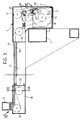
- the loading platform of a truck is indicated P and is supported in conventional manner by a chassis T of the vehicle.
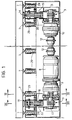
- a housing 1 is fitted to the rear end of the platform P and houses a drive unit 2 for driving a pair of endless chains 3 which extend longitudinally of the platform P in the manner explained below, adjacent its sides and substantially within its thickness.
- the two chains 3 are fixed at 4 adjacent the ends of a low, narrow transverse thrust member 5 in the manner shown in greater detail in Figure 6.
- the cross member 5 extends perpendicular to the length of the platform P and is movable between the front and rear ends thereof by the movement of the two chains 3.
- the drive unit 2 includes a single electric motor 8 with a transverse axis, that is, with its axis parallel to the cross member 5, and two outputs of which one drives a first geared reduction unit 9 directly and the other drives a second geared reduction unit 10 through a transmission shaft 11 and a pair of joints 12.
- Each of the reduction units 9, 10 transmits the drive to a respective sprocket 13 around which the corresponding chain 3 passes.
- Each chain 3 also passes around a first idler sprocket 14 from which its horizontal, lower pass 3a extends along the entire length of the platform P, near the front end of which it passes around a sprocket 15 to a return sprocket 16 from which its horizontal upper pass 3b extends above and parallel to its lower pass 3a.
- the upper pass 3b then passes around a further return sprocket 17 and completes the loop to the drive sprocket 13.
- the sprockets 14 and 17, like the drive sprocket 13, are housed in the housing 1, whilst the sprockets 15 and 16 are housed in a second housing 18 fixed to the chassis T of the vehicle near the front end of the platform P.
- each chain 3 is acted upon by a tensioning sprocket 19 which automatically takes up the natural extension of the chain in use.
- the tensioning sprocket 19 is supported for rotation by a fork 20 which pivots about a transverse shaft 21 between positions shown in continuous outline and broken outline in Figures 3 and 10.
- the fork 20 is subjected to torque by tension springs 22 which urge the tensioning sprocket 19 towards the front end of the platform P against the chain 3, the fork carrying a sector 23 with saw-teeth that cooperate with a one-way ratchet pawl 24 which in turn is subject to the action of a tension spring 25.
- the pawl 24 and the teeth 23 act to restrain the support fork 20, and hence the tensioning sprocket 19, in the angular positions they assume from time to time as a result of the extension of the respective chain 3.
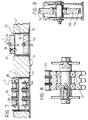
- the lower pass 3a of each of the two chains 3 is movable in a tubular, quadrangular-sectioned profile 26 fitted in a longitudinal through-slot F in the platform P.
- the tubular profile 26 has a base plate 27 fixed to the lower face of the platform P and its upper wall 28 acts as a support for the sliding of the upper pass 3b of the chain 3.
- each cable 7 passes around two grooved wheels or idler pulleys 29, 30 with horizontal axes, from which its lower pass 7a extends longitudinally to the front end of the platform P where it passes around two further idler pulleys 31, 32 from which its upper pass 7b extends parallel to and adjacent its lower pass 7a.
- the upper pass 7b is fixed to the cross member 5 at 6.
- each cable 7 extends within a tubular quadrangular-sectioned profile 33 fitted in a corresponding longitudinal through-slot F' in the platform P and having a base plate 34 fixed to the lower face of the platform P.
- a guide 35 of strong plastics material with a low coefficient of friction is fixed in the bottom of the tubular profile 33 and has a semicircular-sectioned groove 36 in which the lower pass 7a of the cable 7 can slide.
- a similar guide 37 is fixed externally to the top of the section 33 and projects above the upper face of the platform P.
- the guide 37 which, conveniently, is simply fixed to the upper wall of the tubular element 33 by rivets 38, also has an upper semicircular groove 39 in which the upper pass 7b of the cable 7 can slide.
- the guides 35 and 37 are normally of the type described and illustrated in the Applicant's European patent EP-C-240524.
- the upper passes 7b of the cables 7 thus extend at a level above the platform P in order to support and move the loads present thereon, whilst the upper passes 3b of the two chains 3 extend at a lower level substantially flush with the upper surface of the platform P.
- the function of the chains 3 is solely to transmit the drive from the motor 8 to the cross member 5, which in turn moves the cables 7 for loading and unloading operations.
- the device according to the invention on the one hand enables the cross member 5 to be considerably smaller and, on the other hand, simplifies the operations needed to install it in a truck, for which it is necessary simply to form the slots F, F' in which the tubular sections 26 and 33 can be fitted and then to fix the housing 1 with the drive unit 2 and the housing 18 with the respective idler sprockets and pulleys in the rear and front regions of the platform P respectively.
- any maintenance of the drive unit 2 is considerably easier since it is in a region of the platform P which is not affected by the load and is thus readily accessible.
Landscapes
- Engineering & Computer Science (AREA)
- Transportation (AREA)
- Mechanical Engineering (AREA)
- Devices For Conveying Motion By Means Of Endless Flexible Members (AREA)
- Power-Operated Mechanisms For Wings (AREA)
- Loading Or Unloading Of Vehicles (AREA)
Applications Claiming Priority (2)
| Application Number | Priority Date | Filing Date | Title |
|---|---|---|---|
| ITTO910176A IT1245448B (it) | 1991-03-13 | 1991-03-13 | Dispositivo di carico e scarico per autoveicoli |
| ITTO910176 | 1991-03-13 |
Publications (2)
| Publication Number | Publication Date |
|---|---|
| EP0508032A2 true EP0508032A2 (fr) | 1992-10-14 |
| EP0508032A3 EP0508032A3 (en) | 1992-12-09 |
Family
ID=11409059
Family Applications (1)
| Application Number | Title | Priority Date | Filing Date |
|---|---|---|---|
| EP19910830338 Withdrawn EP0508032A3 (en) | 1991-03-13 | 1991-07-30 | A device for loading and unloading motor vehicles |
Country Status (4)
| Country | Link |
|---|---|
| US (1) | US5171122A (fr) |
| EP (1) | EP0508032A3 (fr) |
| CA (1) | CA2048853A1 (fr) |
| IT (1) | IT1245448B (fr) |
Cited By (1)
| Publication number | Priority date | Publication date | Assignee | Title |
|---|---|---|---|---|
| EP0611676A1 (fr) * | 1993-02-16 | 1994-08-24 | SPACE S.r.l. | Appareil motorisé pour charger et décharger des camions et similaires |
Families Citing this family (3)
| Publication number | Priority date | Publication date | Assignee | Title |
|---|---|---|---|---|
| US5664663A (en) * | 1996-06-25 | 1997-09-09 | Wilkens; Arthur L. | Reciprocating floor conveyor |
| US8371434B2 (en) * | 2009-07-23 | 2013-02-12 | Balanced Enterprise Solutions, Llc | Conveyor assembly |
| CA2709797C (fr) * | 2009-12-10 | 2013-02-12 | Harvey Stewart | Module de plancher actif leger pour remorques |
Family Cites Families (15)
| Publication number | Priority date | Publication date | Assignee | Title |
|---|---|---|---|---|
| US2512339A (en) * | 1948-04-22 | 1950-06-20 | Jr Fred E Knapp | Ejector unloading apparatus for vehicles |
| US3008565A (en) * | 1959-02-13 | 1961-11-14 | Julius Duberstein | Apparatus for intermittently delivering workpieces to receiving means |
| US3250408A (en) * | 1963-09-03 | 1966-05-10 | Mcinnis Conveyors Ltd | Truck loading and unloading device |
| US3656638A (en) * | 1970-03-26 | 1972-04-18 | John L Jacobson | Hay distributor |
| US4082196A (en) * | 1976-04-23 | 1978-04-04 | Lutz David W | Loading and unloading apparatus for vehicles |
| US4204592A (en) * | 1976-04-23 | 1980-05-27 | Lutz David E | Loading and unloading apparatus for vehicles |
| US4249843A (en) * | 1978-09-14 | 1981-02-10 | Kerr Robert J | Apparatus for loading, unloading and stacking hay bales |
| JPS5634534A (en) * | 1979-08-29 | 1981-04-06 | Mitsuo Hayashi | Loading conveyor for truck |
| US4431360A (en) * | 1981-07-22 | 1984-02-14 | Mamoru Maeno | Container for the loading and transporting of goods |
| IT206704Z2 (it) * | 1985-10-02 | 1987-10-01 | Space Spa | Dispositivo di carico e scarico per veicoli |
| FR2608977A1 (fr) * | 1986-12-26 | 1988-07-01 | Thomas Jean | Transport a dechargement par chaine de convoyage |
| US4756659A (en) * | 1987-01-06 | 1988-07-12 | Bader Samuel M | Automated load and unload highway trailer |
| DE3711765A1 (de) * | 1987-04-07 | 1988-10-27 | Strautmann & Soehne | Zugstrang-spannvorrichtung fuer transportboeden |
| US4878635A (en) * | 1987-04-20 | 1989-11-07 | Ancra Corporation | Cargo handling system |
| DE3901895A1 (de) * | 1989-01-23 | 1990-07-26 | Kloeckner Paul Gmbh | Nutzfahrzeug mit reversierbarem ladeboden |
-
1991
- 1991-03-13 IT ITTO910176A patent/IT1245448B/it active IP Right Grant
- 1991-07-30 EP EP19910830338 patent/EP0508032A3/en not_active Withdrawn
- 1991-08-09 CA CA002048853A patent/CA2048853A1/fr not_active Abandoned
- 1991-08-13 US US07/744,314 patent/US5171122A/en not_active Expired - Fee Related
Cited By (2)
| Publication number | Priority date | Publication date | Assignee | Title |
|---|---|---|---|---|
| EP0611676A1 (fr) * | 1993-02-16 | 1994-08-24 | SPACE S.r.l. | Appareil motorisé pour charger et décharger des camions et similaires |
| US5413451A (en) * | 1993-02-16 | 1995-05-09 | Space S.R.L. | Loading and unloading powered apparatus for trucks and the like |
Also Published As
| Publication number | Publication date |
|---|---|
| ITTO910176A0 (it) | 1991-03-13 |
| ITTO910176A1 (it) | 1992-09-13 |
| EP0508032A3 (en) | 1992-12-09 |
| CA2048853A1 (fr) | 1992-07-14 |
| IT1245448B (it) | 1994-09-20 |
| US5171122A (en) | 1992-12-15 |
Similar Documents
| Publication | Publication Date | Title |
|---|---|---|
| CA2213427A1 (fr) | Transporteur a accumulation a bande sans fin | |
| US5104281A (en) | Apparatus for handling goods on industrial vehicles | |
| US4414778A (en) | Tape drive door operator | |
| US6123028A (en) | Conveyor for a load-moving system | |
| US20040211649A1 (en) | Conveyor for transporting load carriers | |
| EP1724217B1 (fr) | Dispositif d'entraînement d'une bande transporteuse comprenant une chaîne de transport | |
| US5881859A (en) | Escalator handrail drive mechanism | |
| US5165348A (en) | Conveyor having self-propelled carriers and track with pivotal ratchet pawl teeth to ensure smooth transition between friction drive and pinion drive | |
| US5174217A (en) | Conveyor having self-propelled carriers with a first motor for high speed driving and a second motor for low speed driving | |
| US5171122A (en) | Device for loading and unloading motor vehicles | |
| EP1004504A1 (fr) | Dispositif de propulsion | |
| EP0240524B1 (fr) | Dispositif pour charger et decharger des vehicules | |
| US5647474A (en) | Structure for preventing position deviation of a truck loaded on a traverser | |
| US4880109A (en) | Chain hauled conveyor belt | |
| CA1239610A (fr) | Convoyeur a chaine permettant l'accumulation de chariots sur la chaine | |
| EP0002056A1 (fr) | Véhicules ayant une plate-forme amovible | |
| US4254710A (en) | Link-loc chainless haulage system | |
| GB2170767A (en) | Drive transmission for an overhead rail conveyor system | |
| US3107773A (en) | Drive mechanism for an escalator | |
| JP2003201084A (ja) | 乗客コンベア | |
| WO1992004263A1 (fr) | Appareil de transport | |
| JP4326076B2 (ja) | マンコンベア | |
| US5174213A (en) | Floor mounted automobile conveyor | |
| SU1634617A1 (ru) | Привод от колес автомобил | |
| SU1692913A1 (ru) | Изгибающийс передвижной конвейер |
Legal Events
| Date | Code | Title | Description |
|---|---|---|---|
| PUAI | Public reference made under article 153(3) epc to a published international application that has entered the european phase |
Free format text: ORIGINAL CODE: 0009012 |
|
| AK | Designated contracting states |
Kind code of ref document: A2 Designated state(s): AT BE CH DE DK ES FR GB GR IT LI LU NL SE |
|
| PUAL | Search report despatched |
Free format text: ORIGINAL CODE: 0009013 |
|
| AK | Designated contracting states |
Kind code of ref document: A3 Designated state(s): AT BE CH DE DK ES FR GB GR IT LI LU NL SE |
|
| STAA | Information on the status of an ep patent application or granted ep patent |
Free format text: STATUS: THE APPLICATION IS DEEMED TO BE WITHDRAWN |
|
| 18D | Application deemed to be withdrawn |
Effective date: 19930610 |