EP0508043A2 - Nozzle for plasticising cylinder of a plastic injection moulding machine - Google Patents
Nozzle for plasticising cylinder of a plastic injection moulding machine Download PDFInfo
- Publication number
- EP0508043A2 EP0508043A2 EP92100781A EP92100781A EP0508043A2 EP 0508043 A2 EP0508043 A2 EP 0508043A2 EP 92100781 A EP92100781 A EP 92100781A EP 92100781 A EP92100781 A EP 92100781A EP 0508043 A2 EP0508043 A2 EP 0508043A2
- Authority
- EP
- European Patent Office
- Prior art keywords
- nozzle
- closure body
- channel
- section
- injection
- Prior art date
- Legal status (The legal status is an assumption and is not a legal conclusion. Google has not performed a legal analysis and makes no representation as to the accuracy of the status listed.)
- Granted
Links
Images

Classifications
-
- B—PERFORMING OPERATIONS; TRANSPORTING
- B29—WORKING OF PLASTICS; WORKING OF SUBSTANCES IN A PLASTIC STATE IN GENERAL
- B29C—SHAPING OR JOINING OF PLASTICS; SHAPING OF MATERIAL IN A PLASTIC STATE, NOT OTHERWISE PROVIDED FOR; AFTER-TREATMENT OF THE SHAPED PRODUCTS, e.g. REPAIRING
- B29C45/00—Injection moulding, i.e. forcing the required volume of moulding material through a nozzle into a closed mould; Apparatus therefor
- B29C45/17—Component parts, details or accessories; Auxiliary operations
- B29C45/20—Injection nozzles
- B29C45/23—Feed stopping equipment
- B29C45/234—Valves opened by the pressure of the moulding material
Definitions
- the invention relates to an open nozzle with a central nozzle channel for the heatable plasticizing cylinder of an injection molding unit injecting the plasticized plastic into an injection mold, in which plasticizing cylinder the plastic is plasticized by a rotating screw conveyor when the nozzle rests on the sprue opening of the injection mold and then by an axial return stroke (decompression stroke ) this screw is decompressed in such a way that it does not exit the nozzle channel even after the nozzle has been removed from the injection mold.
- a nozzle is e.g. 4 of DE 37 44 519 C2 known.
- open nozzle in the above sense is to be understood a nozzle that works without a closing needle, if necessary, closing the nozzle mouth, whereby after the decompression stroke thanks to the removal of the compression in the plasticized material or thanks to a limited negative pressure in the plasticized material, this also after stopping Nozzle from the injection mold does not come out of the nozzle.
- Frlacing the nozzle in the above sense means an axial movement of the plasticizing cylinder, in which the contact surface of the nozzle is at a distance from the injection mold.
- the known nozzle is intended and suitable for use in a plastic injection molding unit which prepares and injects the plastic material in the course of an injection cycle as follows: A predetermined quantity of plastic material with or without specific additives is continuously produced by the screw conveyor rotating in the plasticizing cylinder plasticized. Escaping the plasticized material from the nozzle is prevented by the fact that its contact surface rests against the sprue opening of the injection mold, which gate is closed by the sprue of a finished molding or by the molding itself. Then the plastic material plasticized by the screw conveyor is decompressed with the aid of a backward stroke (decompression stroke) of the screw conveyor.
- Decompression means that the plasticized material does not escape from the nozzle even after the nozzle has been removed from the injection mold, thanks to the elimination of the excess pressure or the occurrence of a limited negative pressure.
- the plastic injection molding unit works in the following steps: applying the nozzle; Injecting the material plasticized in a previous injection cycle by an axial stroke of the screw conveyor; Plasticizing the predetermined quantity of plastic; Decompression of the plasticized plastic; Depositing the nozzle from the injection mold for a period of time in which the injection molding previously formed in the injection mold is cooled and removed from the mold; Put the nozzle back on and inject the plasticized plastic.
- the invention has for its object to develop a generic nozzle such that the structural and / or color changes mentioned on the molding can be avoided.
- a limited axially movable closure body is arranged in an end section of a larger clear width of the nozzle channel, which allows the plasticized plastic to flow over from the nozzle channel to the nozzle mouth in a front position (injection position) and under the action in a rear closure position of the decompression stroke closes the end of the nozzle channel.
- the closure body In such a nozzle, the closure body is supported in a front position (FIG. 1, 2) on corresponding support surfaces of the nozzle mouthpiece when the rotating and retracting screw conveyor plasticizes the plastic material and accumulates in front of it. In this position (injection position) of the closure body, injection of the plastic is possible because the plasticized plastic flows around the closure body and can thus reach the nozzle mouth.
- the closure body is transferred as a result of a slight negative pressure in the plasticized plastic into its rearward closure position, in which it lies with the outer surface of its rear, conical end on the shoulder of the sleeve and thereby closes the nozzle channel at the end (Fig. 3).
- the closure body represents an automatically operating decompression lock, which ensures that the plasticized material prepared for the injection is shielded from atmospheric influences after the decompression stroke when the nozzle is lifted off the injection mold.
- the closure body adheres or sticks to the plastic melt when it is transferred from its injection position into its closed position.
- the adhesive effect is significantly increased by the relatively large adhesive surface, which is formed by the large surface of the extension on the closure body. Thanks to the adhesive effect, part of the decompression stroke that is otherwise required can be dispensed with. The latter can be minimized to such an extent that it is just sufficient to move the closure body from its injection position into its closed position.
- the invention is not affected by the fact that, in the case of special injection molding machines with two plasticizing cylinders operating simultaneously, for the production of colored marbled moldings, e.g. of petals or the like is known to alternately close or open the feed channels from the two plasticizing cylinders with a flying closure body.
- a special nozzle system ensures that plastics of different colors or different structures get into the mold cavity of the injection mold in a periodic change (US Pat. No. 4,190,409; 3,945,784).
- the nozzle works without a closing needle closing the nozzle mouth 14 if necessary and is therefore referred to as an 'open' nozzle. It has a central, coaxial to the spray axis Nozzle channel 16.
- the nozzle is intended and suitable for the heatable plasticizing cylinder of an injection molding unit that injects the plasticized plastic into an injection mold.
- the plastic is plasticized by a rotating screw conveyor when the nozzle rests against the sprue opening of the injection mold and then decompressed by an axial return stroke (decompression stroke) of this screw conveyor in such a way that it also emerges from the injection channel 16 after the nozzle has been removed from the injection mold does not emerge.
- a closure body 12 which is axially movable to a limited extent is arranged. In a front position (injection position), this allows the plasticized plastic to flow over from the nozzle channel 16 to the nozzle mouth 14. In a rearward closed position, the closure body covers the nozzle channel 16 at the end under the effect of the decompression stroke.
- the closure body which is approximately radially symmetrical in its basic form, has a cylindrical middle section and runs out on both sides into conical end sections 12d and 12c.
- the front conical end section 12b is provided with grooves 15 running parallel to its lateral surface.
- the nozzle is constructed from a nozzle body 10, a nozzle head 11 and a cylindrical sleeve 13 delimiting the nozzle channel 16 in the section of the nozzle head 11.
- the clear width of the sleeve 13 corresponds to the clear width of the nozzle channel 16 in the section of the nozzle body 10.
- the sleeve 13 also delimits the front end section 16 'of a larger clear width of the nozzle channel 16.
- This end section 16' has a shoulder which serves as a seat for the closure body 12 18 on.
- an annular space 17 is formed between the sleeve 13 and the closure body 12 in the injection position.
- the closure body 12 is provided with a shoulder 12a with a cross-shaped cross-sectional profile which is guided in the nozzle channel 16.
- This approach 12a ensures that the movements of the closure body 12 from its injection position to the closed position and vice versa are strictly axial.
- the one with a plan Contact surface 11b provided nozzle head 11 has a rear portion of smaller diameter, which is provided with an external thread 11a. This is in engagement with the internal thread of a central bore of the nozzle body 10.
- the closure body 12 In the injection position, the closure body 12 is axially supported with the lateral surface of its front conical end section 12b by a correspondingly inclined support surface 11c of the nozzle head 11. If the closure body 12 is in the closed position, the lateral surface of its rear, conical end section 12c lies sealingly against the correspondingly inclined shoulder 18 of the sleeve 13.
- the radially symmetrical basic body of the closure body 12 consisting of the cylindrical central section and the two conical end sections, has a plane of symmetry b-b running perpendicular to the axis of the nozzle, as can be seen particularly in FIG. 7.
- the crosswise arranged grooves 15 extend into the central cylindrical portion of the closure body. However, they end at a distance from the rear conical end section 12c. This ensures that the entrances to the grooves on the annular space 17 are open with a full flow cross-section when the closure body 12 is in the injection position (FIGS. 1, 2).
- the end faces of the conical end sections 12b, 12c enclose an angle of approximately 28 ° to the plane of symmetry b-b in the illustrative embodiment. Since the grooves have the same depth throughout and run parallel to the lateral surfaces of these end sections, there is a corresponding inclination also for the grooves 15. The depth of the annular space 17 measured in the radial direction is approximately a quarter to a third of the clear width of the nozzle mouth 14 .
- the outer surface of the conical end section 12c lies only in a relatively small edge area on the shoulder 18 of the sleeve 13 serving as a seat, so that under the effect of the decompression stroke there is a sufficiently tight contact of the closure body 12 with the Shoulder 18 results.
Landscapes
- Engineering & Computer Science (AREA)
- Manufacturing & Machinery (AREA)
- Mechanical Engineering (AREA)
- Injection Moulding Of Plastics Or The Like (AREA)
Abstract
In einem Endabschnitt größerer lichter Weite des Düsenkanals (16) ist ein begrenzt axial bewegbarer Verschlußkörper (12) angeordnet. Dieser Verschlußkörper läßt in einer vorderen Position (Einspritzposition) ein Überströmen des plastifizierten Kunststoffes vom Düsenkanal (16) zur Düsenmündung (14) zu. In einer rückwärtigen Verschlußposition schirmt der Verschlußkörper (12) den Düsenkanal (16) unter der Wirkung eines Dekompressionshubes stirnseitig ab. Der Dekompressionshub besteht aus einem axialen Rückhub der den plastifizierten Kunststoff in eine Spritzgießform einspritzenden Förderschnecke. Durch eine solche Ausbildung können unerwünschte partielle und strukturelle farbliche Veränderungen am fertigen Spritzling vermieden werden.
Description
Die Erfindung betrifft eine offene Düse mit zentralem Düsenkanal für den beheizbaren Plastifizierzylinder einer den plastifizierten Kunststoff in eine Spritzgießform einspritzenden Spritzgießeinheit, in welchem Plastifizierzylinder der Kunststoff bei Anlage der Düse an der Angußöffnung der Spritzgießform von einer rotierenden Förderschnecke plastifiziert und danach durch einen axialen Rückhub (Dekompressionshub) dieser Förderschnecke derart dekomprimiert wird, daß er auch nach Absetzen der Düse von der Spritzgießform aus dem Düsenkanal nicht austritt. Eine solche Düse ist z.B. aus Fig. 4 der DE 37 44 519 C2 bekannt.The invention relates to an open nozzle with a central nozzle channel for the heatable plasticizing cylinder of an injection molding unit injecting the plasticized plastic into an injection mold, in which plasticizing cylinder the plastic is plasticized by a rotating screw conveyor when the nozzle rests on the sprue opening of the injection mold and then by an axial return stroke (decompression stroke ) this screw is decompressed in such a way that it does not exit the nozzle channel even after the nozzle has been removed from the injection mold. Such a nozzle is e.g. 4 of DE 37 44 519 C2 known.
Unter "offener Düse" im obigen Sinn ist eine Düse zu verstehen, die ohne eine die Düsenmündung bedarfsweise abschließende Verschlußnadel arbeitet, wobei nach dem Dekompressionshub dank einer Aufhebung der Kompression im plastifizierten Material bzw. dank eines begrenzten Unterdruckes im plastifizierten Material dieses auch nach Absetzen der Düse von der Spritzgießform aus der Düse nicht austritt.Under "open nozzle" in the above sense is to be understood a nozzle that works without a closing needle, if necessary, closing the nozzle mouth, whereby after the decompression stroke thanks to the removal of the compression in the plasticized material or thanks to a limited negative pressure in the plasticized material, this also after stopping Nozzle from the injection mold does not come out of the nozzle.
Unter "Absetzen der Düse" im obigen Sinne wird eine axiale Bewegung des Plastifizierzylinders verstanden, bei der die Anlagefläche der Düse im Abstand von der Spritzgießform gelangt."Placing the nozzle" in the above sense means an axial movement of the plasticizing cylinder, in which the contact surface of the nozzle is at a distance from the injection mold.
Die bekannte Düse ist zur Benutzung in einer Kunststoff-Spritzgießeinheit bestimmt und geeignet, welche das Kunststoffmaterial im Verlauf eines Spritzzyklus wie folgt aufbereitet und einspritzt: Ein vorbestimmtes Quantum an Kunststoffmaterial mit oder ohne spezifische Zusätze wird von der im Plastifizierzylinder rotierenden Förderschnecke fortlaufend plastifiziert. Ein Austreten des plastifizierten Materials aus der Düse wird dabei dadurch verhindert, daß diese mit ihrer Anlagefläche an der durch den Anguß eines fertigen Spritzlings bzw. durch den Spritzling selbst geschlossenen Angußöffnung der Spritzgießform anliegt. Danach wird das von der Förderschnecke plastifizierte Kunststoffmaterial mit Hilfe eines nach rückwärts gerichteten Hubes (Dekompressionshub) der Förderschnecke dekomprimiert. Die Dekomprimierung hat zur Folge, daß das plastifizierte Material auch nach Absetzen der Düse von der Spritzgießform dank der Beseitigung des Überdruckes bzw. des Auftretens eines begrenzten Unterdruckes aus der Düse nicht austritt. Insgesamt arbeitet die Kunststoff-Spritzgießeinheit in folgenden Schritten: Anlegen der Düse; Einspritzen des in einem vorausgegangenen Spritzzyklus plastifizierten Materials durch einen Axialhub der Förderschnecke; Plastifizieren des vorbestimmten Kunststoffquantums; Dekompression des plastifizierten Kunststoffes; Absetzen der Düse von der Spritzgießform für eine Zeitspanne, in welcher der zuvor in der Spritzgießform gebildete Spritzling abkühlt und entformt wird; erneutes Anlegen der Düse und Einspritzen des plastifizierten Kunststoffes.The known nozzle is intended and suitable for use in a plastic injection molding unit which prepares and injects the plastic material in the course of an injection cycle as follows: A predetermined quantity of plastic material with or without specific additives is continuously produced by the screw conveyor rotating in the plasticizing cylinder plasticized. Escaping the plasticized material from the nozzle is prevented by the fact that its contact surface rests against the sprue opening of the injection mold, which gate is closed by the sprue of a finished molding or by the molding itself. Then the plastic material plasticized by the screw conveyor is decompressed with the aid of a backward stroke (decompression stroke) of the screw conveyor. Decompression means that the plasticized material does not escape from the nozzle even after the nozzle has been removed from the injection mold, thanks to the elimination of the excess pressure or the occurrence of a limited negative pressure. Overall, the plastic injection molding unit works in the following steps: applying the nozzle; Injecting the material plasticized in a previous injection cycle by an axial stroke of the screw conveyor; Plasticizing the predetermined quantity of plastic; Decompression of the plasticized plastic; Depositing the nozzle from the injection mold for a period of time in which the injection molding previously formed in the injection mold is cooled and removed from the mold; Put the nozzle back on and inject the plasticized plastic.
Bei Düsen der eingangs genannten Gattung treten verschiedentlich unerwünschte partielle, strukturelle und farbliche Veränderungen am fertigen Spritzling, z.B. Schlieren, auf. Diese sind auf unterschiedliche Ursachen, z.B. auf partielle Überhitzung bei Aufbereitung des Kunststoffes im Plastifizierzylinder oder Verunreinigungen usw. zurückzuführen. In langfristigen Beobachtungen wurde erkannt, daß solche Veränderungen zu vermeiden sind, wenn man den plastifizierten Kunststoff im Bereich der offenen Düse gegenüber der Atmosphäre abschirmt. Daraus kann gefolgert werden, daß als Ursache für die genannten Veränderungen auch komplexe, im einzelnen nicht abgeklärte Oxydationsprozesse, aber auch das Eindringen von Wasserdampf in die Kunststoffschmelze in Betracht kommen können.In the case of nozzles of the type mentioned at the outset, undesired partial, structural and color changes occur on the finished molded part, e.g. Streaks, on. These are due to different causes, e.g. due to partial overheating when processing the plastic in the plasticizing cylinder or contamination etc. Long-term observations have shown that such changes can be avoided if the plasticized plastic is shielded from the atmosphere in the area of the open nozzle. From this it can be concluded that complex, not yet clarified oxidation processes, but also the penetration of water vapor into the plastic melt can be considered as the cause of the changes mentioned.
Der Erfindung liegt die Aufgabe zugrunde, eine gattungsgemäße Düse derart weiterzubilden, daß die genannten strukturellen und/oder farblichen Veränderungen am Spritzling vermieden werden können.The invention has for its object to develop a generic nozzle such that the structural and / or color changes mentioned on the molding can be avoided.
Diese Aufgabe wird erfindungsgemäß dadurch gelöst, daß in einem Endabschnitt größerer lichter Weite des Düsenkanals ein begrenzt axial bewegbarer Verschlußkörper angeordnet ist, der in einer vorderen Position (Einspritzposition) ein Überströmen des plastifizierten Kunststoffes vom Düsenkanal zur Düsenmündung zuläßt und in einer rückwärtigen Verschlußposition unter der Wirkung des Dekompressionshubes den Düsenkanal stirnseitig abschließt.This object is achieved in that a limited axially movable closure body is arranged in an end section of a larger clear width of the nozzle channel, which allows the plasticized plastic to flow over from the nozzle channel to the nozzle mouth in a front position (injection position) and under the action in a rear closure position of the decompression stroke closes the end of the nozzle channel.
Bei einer solchen Düse ist der Verschlußkörper in einer vorderen Position (Fig.1, 2) an entsprechenden Stützflächen des Düsenmundstückes abgestützt, wenn die rotierende und zurückweichende Förderschnecke das Kunststoffmaterial plastifiziert und vor sich ansammelt. In dieser Position (Einspritzposition) des Verschlußkörpers ist eine Einspritzung des Kunststoffes möglich, weil der plastifizierte Kunststoff den Verschlußkörper umströmen und dadurch zur Düsenmündung gelangen kann. Beim Dekompressionshub wird der Verschlußkörper im Gefolge eines geringfügigen Unterdruckes im plastifizierten Kunststoff in seine rückwärtige Verschlußposition überführt, in welcher er mit der Mantelfläche seines rückwärtigen kegelförmigen Endes an der Schulter der Hülse anliegt und dadurch den Düsenkanal stirnseitig abschließt (Fig. 3). Insoweit stellt der Verschlußkörper einen automatisch arbeitenden Dekompressionsverschluß dar, der sicherstellt, daß das für die Einspritzung vorbereitete plastifizierte Material nach dem Dekompressionshub von atmosphärischen Einflüssen abgeschirmt ist, wenn die Düse von der Spritzgießform abgehoben ist.In such a nozzle, the closure body is supported in a front position (FIG. 1, 2) on corresponding support surfaces of the nozzle mouthpiece when the rotating and retracting screw conveyor plasticizes the plastic material and accumulates in front of it. In this position (injection position) of the closure body, injection of the plastic is possible because the plasticized plastic flows around the closure body and can thus reach the nozzle mouth. During the decompression stroke, the closure body is transferred as a result of a slight negative pressure in the plasticized plastic into its rearward closure position, in which it lies with the outer surface of its rear, conical end on the shoulder of the sleeve and thereby closes the nozzle channel at the end (Fig. 3). In this respect, the closure body represents an automatically operating decompression lock, which ensures that the plasticized material prepared for the injection is shielded from atmospheric influences after the decompression stroke when the nozzle is lifted off the injection mold.
Es hat sich gezeigt, daß bei einem solchen Dekompressionsverschluß der Verschlußkörper beim Überführen von seiner Einspritzposition in seine Verschlußposition an der Kunststoffschmelze haftet bzw. klebt. Die Haftwirkung ist durch die relativ große Haftfläche wesentlich verstärkt, welche durch die große Oberfläche des Ansatzes am Verschlußkörper gebildet ist. Dank der Haftwirkung kann auf einen Teil des sonst erforderlichen Dekompressionshubes verzichtet werden. Letzterer kann soweit minimiert werden, daß er gerade noch zur Verschiebung des Verschlußkörpers aus seiner Einspritzposition in seine Verschlußposition ausreicht.It has been shown that with such a decompression seal, the closure body adheres or sticks to the plastic melt when it is transferred from its injection position into its closed position. The adhesive effect is significantly increased by the relatively large adhesive surface, which is formed by the large surface of the extension on the closure body. Thanks to the adhesive effect, part of the decompression stroke that is otherwise required can be dispensed with. The latter can be minimized to such an extent that it is just sufficient to move the closure body from its injection position into its closed position.
Die Erfindung wird dadurch nicht berührt, daß es bei speziellen Spritzgießmaschinen mit zwei gleichzeitig arbeitenden Plastifizierzylindern zur Herstellung von farbmarmorierten Spritzlingen, z.B. von Blumenblättern oder dergleichen bekannt ist, die Zufuhrkanäle aus beiden Plastifizierzylindern wechselweise mit einem fliegenden Verschlußkörper abzuschließen bzw. zu öffnen. Ein solches spezielles Düsensystem stellt sicher, daß Kunststoffe unterschiedlicher Farbe bzw. unterschiedlicher Struktur im periodischen Wechsel in den Formhohlraum der Spritzgießform gelangen (US-PS 4,190,409; 3,945,784).The invention is not affected by the fact that, in the case of special injection molding machines with two plasticizing cylinders operating simultaneously, for the production of colored marbled moldings, e.g. of petals or the like is known to alternately close or open the feed channels from the two plasticizing cylinders with a flying closure body. Such a special nozzle system ensures that plastics of different colors or different structures get into the mold cavity of the injection mold in a periodic change (US Pat. No. 4,190,409; 3,945,784).
Nachstehend wird die Erfindung anhand eines Ausführungsbeispiels erläutert.The invention is explained below using an exemplary embodiment.
Es zeigen:
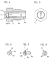
- Fig. 1
- den vorderen Teil der Düse im vertikalen Schnitt bei in Einspritzposition befindlichem Verschlußkörper,
- Fig. 2 und 3
- den Düsenkopf der Düse bei in Einspritzposition und in Verschlußposition befindlichem Verschlußkörper in einer Darstellung entsprechend Fig. 1,
- Fig. 4, 5
- den Düsenkopf gemäß Fign. 2, 3 ohne Verschlußkörper und in Seiten- und Stirnansicht und
- Fig. 6, 7, 8
- den Verschlußkörper in Rückansicht, Seitenansicht und Stirnansicht.
- Fig. 1
- the front part of the nozzle in vertical section with the closure body in the injection position,
- 2 and 3
- 1 shows the nozzle head of the nozzle with the closure body in the injection position and in the closure position, in a representation corresponding to FIG. 1,
- 4, 5
- the nozzle head according to FIGS. 2, 3 without closure body and in side and front view and
- 6, 7, 8
- the closure body in rear view, side view and front view.
Die Düse arbeitet ohne eine die Düsenmündung 14 bedarfsweise abschließende Verschlußnadel und wird daher als 'offene' Düse bezeichnet. Sie weist einen zentralen, zur Spritzachse koaxialen Düsenkanal 16 auf. Die Düse ist für den beheizbaren Plastifizierzylinder einer den plastifizierten Kunststoff in eine Spritzgießform einspritzenden Spritzgießeinheit bestimmt und geeignet. Im Plastifizierzylinder einer solchen Spritzgießeinheit wird der Kunststoff bei Anlage der Düse an der Angußöffnung der Spritzgießform von einer rotierenden Förderschnecke plastifiziert und danach durch einen axialen Rückhub (Dekompressionshub) dieser Förderschnecke derart dekomprimiert, daß er auch nach Absetzen der Düse von der Spritzgießform aus dem Düsenkanal 16 nicht austritt. In einem Endabschnitt 16' größerer lichter Weite des Düsenkanals 16 ist ein begrenzt axial bewegbarer Verschlußkörper 12 angeordnet. Dieser läßt in einer vorderen Position (Einspritzposition) ein Überströmen des plastifizierten Kunststoffes vom Düsenkanal 16 zur Düsenmündung 14 zu. In einer rückwärtigen Verschlußposition deckt der Verschlußkörper unter Wirkung des Dekompressionshubes den Düsenkanal 16 stirnseitig ab. Der in seiner Grundform etwa radialsymmetrische Verschlußkörper weist einen zylindrischen Mittelabschnitt auf und läuft beidseits in kegelförmige Endabschnitte 12d und 12c aus. Der vordere kegelförmige Endabschnitt 12b ist mit parallel zu seiner Mantelfläche verlaufenden Nuten 15 versehen.The nozzle works without a closing needle closing the
Die Düse ist aus einem Düsenkörper 10, einem Düsenkopf 11 und einer den Düsenkanal 16 im Abschnitt des Düsenkopfes 11 begrenzenden zylindrischen Hülse 13 aufgebaut. Die lichte Weite der Hülse 13 entspricht der lichten Weite des Düsenkanals 16 im Abschnitt des Düsenkörpers 10. Die Hülse 13 begrenzt auch den vorderen Endabschnitt 16' größerer lichter Weite des Düsenkanals 16. Dieser Endabschnitt 16' weist eine als Sitz für den Verschlußkörper 12 dienende Schulter 18 auf. Im Bereich des Endabschnittes 16' größerer lichter Weite des Düsenkanals 16 ist zwischen der Hülse 13 und dem in Einspritzposition befindlichen Verschlußkörper 12 ein Ringraum 17 gebildet. Rückseitig ist der Verschlußkörper 12 mit einem im Düsenkanal 16 geführten Ansatz 12a mit kreuzförmigem Querschnittsprofil versehen. Dieser Ansatz 12a gewährleistet, daß die Bewegungen des Verschlußkörpers 12 aus seiner Einspritzposition in die Verschlußposition und umgekehrt streng axial verlaufen. Der mit einer planen Anlagefläche 11b versehene Düsenkopf 11 weist einen rückwärtigen Abschnitt geringeren Durchmessers auf, der mit einem Außengewinde 11a versehen ist. Dieses steht mit dem Innengewinde einer zentralen Bohrung des Düsenkörpers 10 in Eingriff. In Einspritzposition ist der Verschlußkörper 12 mit der Mantelfläche seines vorderen kegelförmigen Endabschnittes 12b von einer entsprechend geneigten Stützfläche 11c des Düsenkopfes 11 axial abgestützt. Befindet sich der Verschlußkörper 12 in Verschlußposition, so liegt die Mantelfläche seines rückwärtigen, kegelförmigen Endabschnittes 12c an der entsprechend geneigten Schulter 18 der Hülse 13 dichtend an.The nozzle is constructed from a
Sieht man von den Nuten 15 und dem Ansatz 12a ab, so weist der radialsymmetrische, aus dem zylindrischen Mittelabschnitt und den beiden kegelförmigen Endabschnitten bestehende Grundkörper des Verschlußkörpers 12 eine rechtwinklig zur Achse der Düse verlaufende Symmetrieebene b-b auf, wie insbesondere aus Fig. 7 ersichtlich. Die kreuzweise angeordneten Nuten 15 erstrecken sich in den mittleren zylindrischen Abschnitt des Verschlußkörpers hinein. Sie enden jedoch im Abstand vom rückwärtigen kegelförmigen Endabschnitt 12c. Dadurch ist sichergestellt, daß die Eingänge zu den Nuten am Ringraum 17 mit vollem Durchflußquerschnitt offen sind, wenn der Verschlußkörper 12 sich in Einspritzposition (Fig. 1, 2) befindet. Die Stirnflächen der kegelförmigen Endabschnitte 12b, 12c schließen im zeichnerischen Ausführungsbeispiel zur Symmetrieebene b-b etwa einen Winkel von 28° ein. Da die Nuten durchgehend eine gleiche Tiefe aufweisen und parallel zu den Mantelflächen dieser Endabschnitte verlaufen, ergibt sich eine entsprechende Neigung auch für die Nuten 15. Die in radialer Richtung gemessene Tiefe des Ringraumes 17 beträgt etwa ein Viertel bis ein Drittel der lichten Weite der Düsenmündung 14.Apart from the
Wie insbesondere aus Fig. 3 ersichtlich, liegt die Mantelfläche des kegelförmigen Endabschnittes 12c lediglich in einem relativ geringen Randbereich an der als Sitz dienenden Schulter 18 der Hülse 13 an, so daß sich unter der Wirkung des Dekompressionshubes eine ausreichend dichte Anlage des Verschlußkörpers 12 an der Schulter 18 ergibt.As can be seen in particular from FIG. 3, the outer surface of the
- 1010th
- DüsenkörperNozzle body
- 1111
- DüsenkopfNozzle head
- 11a11a
- AußengewindeExternal thread
- 11b11b
- plane Anlageflächeflat contact surface
- 1212
- VerschlußkörperClosure body
- 12a12a
- Ansatzapproach
- 12b12b
- vorderer kegelförmiger Abschnittfront conical section
- 12c12c
- rückwärtiger kegelförmiger Abschnittrear conical section
- 1313
- HülseSleeve
- 13a13a
- vorderer Endabschnitt der Hülse größerer lichter Weitefront end portion of the sleeve larger internal width
- 1414
- DüsenmündungNozzle mouth
- 1515
- DurchflußkanäleFlow channels
- 1616
- Düsenkanal ; 16' Endabschnitt (Fig. 4)Nozzle channel; 16 'end section (Fig. 4)
- 1717th
- RingraumAnnulus
- 1818th
- Schultershoulder
Claims (10)
Applications Claiming Priority (2)
| Application Number | Priority Date | Filing Date | Title |
|---|---|---|---|
| DE4111164A DE4111164C1 (en) | 1991-04-06 | 1991-04-06 | |
| DE4111164 | 1991-04-06 |
Publications (3)
| Publication Number | Publication Date |
|---|---|
| EP0508043A2 true EP0508043A2 (en) | 1992-10-14 |
| EP0508043A3 EP0508043A3 (en) | 1992-12-09 |
| EP0508043B1 EP0508043B1 (en) | 1996-03-13 |
Family
ID=6428958
Family Applications (1)
| Application Number | Title | Priority Date | Filing Date |
|---|---|---|---|
| EP92100781A Expired - Lifetime EP0508043B1 (en) | 1991-04-06 | 1992-01-18 | Nozzle for plasticising cylinder of a plastic injection moulding machine |
Country Status (3)
| Country | Link |
|---|---|
| EP (1) | EP0508043B1 (en) |
| AT (1) | ATE135282T1 (en) |
| DE (2) | DE4111164C1 (en) |
Family Cites Families (6)
| Publication number | Priority date | Publication date | Assignee | Title |
|---|---|---|---|---|
| DE1167008B (en) * | 1961-02-11 | 1964-04-02 | Anker Werk Gebr Goller | Device to prevent plasticized plastic from escaping from the injection nozzle of a screw injection molding machine |
| DE1217597B (en) * | 1964-10-15 | 1966-05-26 | Desma Werke Gmbh | Injection nozzle with flat nozzle head for injection molding machines |
| US3396431A (en) * | 1965-04-07 | 1968-08-13 | Modern Plastic Machinery Corp | Screw injector for plastic material |
| US3401426A (en) * | 1966-05-31 | 1968-09-17 | New Britain Machine Co | Plastic injection molding machine |
| US3902665A (en) * | 1974-06-10 | 1975-09-02 | Ex Cell O Corp | Nozzle shut-off valve |
| DE3744519A1 (en) * | 1987-12-30 | 1989-07-13 | Karl Hehl | PLASTICIZING CYLINDER FOR A PLASTIC INJECTION MOLDING UNIT |
-
1991
- 1991-04-06 DE DE4111164A patent/DE4111164C1/de not_active Expired - Lifetime
-
1992
- 1992-01-18 EP EP92100781A patent/EP0508043B1/en not_active Expired - Lifetime
- 1992-01-18 DE DE59205633T patent/DE59205633D1/en not_active Expired - Fee Related
- 1992-01-18 AT AT92100781T patent/ATE135282T1/en active
Also Published As
| Publication number | Publication date |
|---|---|
| EP0508043A3 (en) | 1992-12-09 |
| ATE135282T1 (en) | 1996-03-15 |
| DE4111164C1 (en) | 1992-07-02 |
| DE59205633D1 (en) | 1996-04-18 |
| EP0508043B1 (en) | 1996-03-13 |
Similar Documents
| Publication | Publication Date | Title |
|---|---|---|
| EP0043543B1 (en) | Device for producing multi-layer moulded thermoplastic articles | |
| EP0310914B2 (en) | Method of injection moulding formed parts of thermoplastic resins, and for carrying out this method | |
| DE69722463T2 (en) | DISCHARGE SEAL WITH STOPPER AND METHOD FOR THE PRODUCTION THEREOF | |
| DE2342794A1 (en) | METHOD AND DEVICE FOR THE DISCONTINUOUS MANUFACTURE OF MULTI-LAYER MOLDED PARTS FROM THERMOPLASTIC PLASTIC | |
| DE69228683T2 (en) | NOZZLE FOR GAS SUPPORTED INJECTION MOLDING | |
| DE69624453T2 (en) | Reaction injection molding process for the production of two-tone molded polyurethane parts | |
| EP0161589B1 (en) | Process and device for making a plastic injection-moulded article, especially a profiled listel for a vehicle | |
| DE1704791B2 (en) | DEVICE FOR THE PRODUCTION OF CROSS-SECTION RING-SHAPED BODIES FROM THERMOPLASTIC PLASTIC | |
| DE4404672A1 (en) | Method and device for manufacturing brushes | |
| DE2247995B2 (en) | Method and device for the injection molding of plastic moldings, which consist of a filling layer made of a thermoplastic plastic and a cover layer enclosing this made of another thermoplastic plastic | |
| DE1261657B (en) | Spray head for the production of tubular stretches | |
| EP0467129B1 (en) | Nozzle for injection moulding machines | |
| DE3247000C2 (en) | ||
| DE885152C (en) | Method and machine for pressing or spraying multicolored parts, preferably made of thermoplastics | |
| DE1177326B (en) | Process for the production of artificial flower petals made of thermoplastics and device for carrying out this process | |
| EP3414073B1 (en) | Method for producing a plastic part in the two-component injection moulding method | |
| DE3043275C2 (en) | Injection mold with outer molded parts and a multi-part inner core | |
| DE4111164C1 (en) | ||
| DE19808145A1 (en) | Injection moulding of articles with two components | |
| DE102007045439B3 (en) | Melt mixer or filter unit mounted in injection molding machine nozzle is cylindrical and has central blind bore terminating in channel at downstream end which is closed by ball valve during injection, valve opening when screw is withdrawn | |
| DE1124234B (en) | Injection molding machine for processing thermoplastics | |
| DE19703316A1 (en) | Simple but precise pressure injection moulding method producing cartridge complete with nozzle used to contain e.g. mastic | |
| EP2243613A1 (en) | Nozzle device and method for injecting plastic moulded parts | |
| EP2891551A1 (en) | Injection moulding tool for producing a zip slider and the manufactured zip slider | |
| EP1007318A1 (en) | Method for injection moulding, injection mould, injection moulding device and method for filling a main extruder from a secondary extruder |
Legal Events
| Date | Code | Title | Description |
|---|---|---|---|
| PUAI | Public reference made under article 153(3) epc to a published international application that has entered the european phase |
Free format text: ORIGINAL CODE: 0009012 |
|
| AK | Designated contracting states |
Kind code of ref document: A2 Designated state(s): AT CH DE ES FR GB IT LI NL |
|
| PUAL | Search report despatched |
Free format text: ORIGINAL CODE: 0009013 |
|
| AK | Designated contracting states |
Kind code of ref document: A3 Designated state(s): AT CH DE ES FR GB IT LI NL |
|
| 17P | Request for examination filed |
Effective date: 19930416 |
|
| 17Q | First examination report despatched |
Effective date: 19941010 |
|
| GRAA | (expected) grant |
Free format text: ORIGINAL CODE: 0009210 |
|
| AK | Designated contracting states |
Kind code of ref document: B1 Designated state(s): AT CH DE ES FR GB IT LI NL |
|
| PG25 | Lapsed in a contracting state [announced via postgrant information from national office to epo] |
Ref country code: NL Free format text: LAPSE BECAUSE OF FAILURE TO SUBMIT A TRANSLATION OF THE DESCRIPTION OR TO PAY THE FEE WITHIN THE PRESCRIBED TIME-LIMIT Effective date: 19960313 Ref country code: GB Effective date: 19960313 Ref country code: FR Effective date: 19960313 Ref country code: ES Free format text: THE PATENT HAS BEEN ANNULLED BY A DECISION OF A NATIONAL AUTHORITY Effective date: 19960313 |
|
| REF | Corresponds to: |
Ref document number: 135282 Country of ref document: AT Date of ref document: 19960315 Kind code of ref document: T |
|
| REG | Reference to a national code |
Ref country code: CH Ref legal event code: NV Representative=s name: PATENTANWALTSBUREAU BOSSHARD UND LUCHS |
|
| REF | Corresponds to: |
Ref document number: 59205633 Country of ref document: DE Date of ref document: 19960418 |
|
| ITF | It: translation for a ep patent filed | ||
| NLV1 | Nl: lapsed or annulled due to failure to fulfill the requirements of art. 29p and 29m of the patents act | ||
| EN | Fr: translation not filed | ||
| GBV | Gb: ep patent (uk) treated as always having been void in accordance with gb section 77(7)/1977 [no translation filed] |
Effective date: 19960313 |
|
| PLBE | No opposition filed within time limit |
Free format text: ORIGINAL CODE: 0009261 |
|
| STAA | Information on the status of an ep patent application or granted ep patent |
Free format text: STATUS: NO OPPOSITION FILED WITHIN TIME LIMIT |
|
| PG25 | Lapsed in a contracting state [announced via postgrant information from national office to epo] |
Ref country code: AT Free format text: LAPSE BECAUSE OF NON-PAYMENT OF DUE FEES Effective date: 19970118 |
|
| PG25 | Lapsed in a contracting state [announced via postgrant information from national office to epo] |
Ref country code: LI Effective date: 19970131 Ref country code: CH Effective date: 19970131 |
|
| 26N | No opposition filed | ||
| REG | Reference to a national code |
Ref country code: CH Ref legal event code: PL |
|
| PG25 | Lapsed in a contracting state [announced via postgrant information from national office to epo] |
Ref country code: DE Effective date: 19971001 |
|
| PG25 | Lapsed in a contracting state [announced via postgrant information from national office to epo] |
Ref country code: IT Free format text: LAPSE BECAUSE OF NON-PAYMENT OF DUE FEES;WARNING: LAPSES OF ITALIAN PATENTS WITH EFFECTIVE DATE BEFORE 2007 MAY HAVE OCCURRED AT ANY TIME BEFORE 2007. THE CORRECT EFFECTIVE DATE MAY BE DIFFERENT FROM THE ONE RECORDED. Effective date: 20050118 |