EP0508052A2 - Fehlerstromrelais - Google Patents
Fehlerstromrelais Download PDFInfo
- Publication number
- EP0508052A2 EP0508052A2 EP92101784A EP92101784A EP0508052A2 EP 0508052 A2 EP0508052 A2 EP 0508052A2 EP 92101784 A EP92101784 A EP 92101784A EP 92101784 A EP92101784 A EP 92101784A EP 0508052 A2 EP0508052 A2 EP 0508052A2
- Authority
- EP
- European Patent Office
- Prior art keywords
- leg
- shaped yoke
- armature
- yoke part
- pole
- Prior art date
- Legal status (The legal status is an assumption and is not a legal conclusion. Google has not performed a legal analysis and makes no representation as to the accuracy of the status listed.)
- Granted
Links
- 230000000694 effects Effects 0.000 description 6
- 230000004907 flux Effects 0.000 description 5
- XEEYBQQBJWHFJM-UHFFFAOYSA-N Iron Chemical compound [Fe] XEEYBQQBJWHFJM-UHFFFAOYSA-N 0.000 description 4
- 230000036039 immunity Effects 0.000 description 4
- 230000004043 responsiveness Effects 0.000 description 4
- 230000035939 shock Effects 0.000 description 3
- 238000011161 development Methods 0.000 description 2
- 230000018109 developmental process Effects 0.000 description 2
- 238000010586 diagram Methods 0.000 description 2
- 229910052742 iron Inorganic materials 0.000 description 2
- 239000000463 material Substances 0.000 description 2
- 230000035945 sensitivity Effects 0.000 description 2
- 238000003466 welding Methods 0.000 description 2
- 230000006978 adaptation Effects 0.000 description 1
- 239000000696 magnetic material Substances 0.000 description 1
- 238000011144 upstream manufacturing Methods 0.000 description 1
- 238000004804 winding Methods 0.000 description 1
Images
Classifications
-
- H—ELECTRICITY
- H01—ELECTRIC ELEMENTS
- H01H—ELECTRIC SWITCHES; RELAYS; SELECTORS; EMERGENCY PROTECTIVE DEVICES
- H01H71/00—Details of the protective switches or relays covered by groups H01H73/00 - H01H83/00
- H01H71/10—Operating or release mechanisms
- H01H71/12—Automatic release mechanisms with or without manual release
- H01H71/24—Electromagnetic mechanisms
- H01H71/32—Electromagnetic mechanisms having permanently magnetised part
- H01H71/321—Electromagnetic mechanisms having permanently magnetised part characterised by the magnetic circuit or active magnetic elements
- H01H71/323—Electromagnetic mechanisms having permanently magnetised part characterised by the magnetic circuit or active magnetic elements with rotatable armature
-
- H—ELECTRICITY
- H01—ELECTRIC ELEMENTS
- H01H—ELECTRIC SWITCHES; RELAYS; SELECTORS; EMERGENCY PROTECTIVE DEVICES
- H01H50/00—Details of electromagnetic relays
- H01H50/16—Magnetic circuit arrangements
- H01H50/36—Stationary parts of magnetic circuit, e.g. yoke
-
- H—ELECTRICITY
- H01—ELECTRIC ELEMENTS
- H01H—ELECTRIC SWITCHES; RELAYS; SELECTORS; EMERGENCY PROTECTIVE DEVICES
- H01H50/00—Details of electromagnetic relays
- H01H50/02—Bases; Casings; Covers
- H01H50/04—Mounting complete relay or separate parts of relay on a base or inside a case
- H01H50/041—Details concerning assembly of relays
- H01H2050/046—Assembling parts of a relay by using snap mounting techniques
-
- H—ELECTRICITY
- H01—ELECTRIC ELEMENTS
- H01H—ELECTRIC SWITCHES; RELAYS; SELECTORS; EMERGENCY PROTECTIVE DEVICES
- H01H50/00—Details of electromagnetic relays
- H01H50/16—Magnetic circuit arrangements
- H01H50/36—Stationary parts of magnetic circuit, e.g. yoke
- H01H50/40—Branched or multiple-limb main magnetic circuits
Definitions
- the invention relates to a residual current relay, consisting of a magnet system arranged in a housing with a spring-loaded hinged armature, the triggering movement of which is transmitted to a plunger arranged above the armature on the housing, the magnet system being formed from a U-shaped yoke, on the armature-remote pole leg of the coil former with fault current connection.
- a fault current relay of this type is known, for example, from DE-A-17 64 921.
- the plunger interacts with the hinged armature, which is arranged essentially perpendicular to the armature and through which the switching movement of the armature is transmitted to the actual circuit breaker. If there is no fault current, the hinged armature rests on the pole faces of the magnet system against the spring action, and is held by the pulling force of the permanent magnet, which is part of the magnet system.
- the invention is therefore based on the object to improve residual current relays of the generic type with simple means in such a way that with at least comparatively the same immunity to interference of previous relays, the power consumption is significantly reduced and thus the responsiveness to residual currents can be increased.
- the pole faces of the permanent magnet located in the shunt are fully integrated into the overall magnetic system, as a result of which the magnetic force flow is optimally introduced into the soft magnetic material and saturation effects in the circles of the magnetic force flows are avoided when the state of charge of the permanent magnet reaches a maximum value does not exceed.
- the shunt resistance is much larger than the resistances generated by the air gaps between the hinged armature and the pole faces of the yoke, the impedance of the relays is largely constant at the operating point and depends only to a small extent on the tripping power.
- the shunt resistance is precisely defined by the one inserted between the yoke parts non-magnetic film. All of this together with the practically loss-free opening mechanism guarantees stable operation with a power consumption of only 50 ⁇ VA and with at least the same immunity to mechanical shocks as previous FI relays, but the power consumption is much higher.
- the effect according to the invention namely to be able to substantially reduce the power consumption with at least comparatively the same immunity to interference of previous relays, is based on the fact that the magnetic resistance of the iron in the magnetic circuit is not neglected. Without iron magnetic resistance there would be no saturation effects. These saturation effects can only occur in the shunt circuit due to the geometric structure of the yoke according to the invention, as a result of which the main circuit which is decisive for the sensitivity of the relay remains magnetically soft.
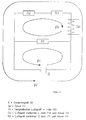
- FIG. 1 shows an equivalent circuit diagram for the entire magnetic system on which the relay is based if the magnetic resistance of the yoke and armature material is neglected in a first approximation.
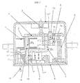
- the residual current relay consists of a magnet system arranged in a housing 4 with a spring-loaded hinged armature 2, the triggering movement of which a plunger 3 arranged above the armature 2 on the housing 4 is transmitted, the magnet system being formed from a U-shaped yoke J, on the pole leg 11 'remote from the armature bearing, the coil former 1 with fault current connection 12 is seated.
- the U-shaped yoke J is formed from an L-shaped yoke part 11 and an S-shaped yoke part 7, which has its leg 7 'below the coil former 1 with the interposition of a non-magnetic film 10 on the pole leg 11 'is present, the permanent magnet 9 of the magnet system between the short leg 11' 'of the yoke part 11 and the connecting web of the leg 7' and the pole leg 7 '' of the S-shaped yoke part forming the base web 7 '' 'of the u-shaped yoke J 7 is arranged.
- the housing 4 is designed as a hood enclosing the entire system and seated on a base plate 8, in which the plunger 3 is arranged in a guide at the top, which, for example, has a stroke of at least 2 mm with sufficient force to actuate the lock in the FI Should be able to bridge switches.
- the internal magnetic circuit consists of the permanent magnet 9, the L-yoke part 11, the S-yoke part 7 and the film 10.
- the L-yoke part 11, the films 10 and the S-yoke part 7 are each on the right by two laser welding points (not shown) and firmly connected on the left.
- the permanent magnet 9 is attached to the L-yoke 11 at the bottom left and right by a laser welding point.
- the coil former 1 sits on the pole leg 11 'of the L-yoke part 11 and is clipped to the base plate 8.
- the armature holder 6 is seated on the pole leg 7 ′′ of the S-yoke part 7.
- the armature holding shaft 13 is guided in two lateral guides in the armature holder 6 and has a rectangular mandrel 13 ′ which is caulked in the hinged armature 2 and is thus firmly connected to it .
- a tension spring 5 is suspended at the end of the anchor, the other end of which is attached to the base plate 8. In the closed relay state, this tension spring 5 is biased by a fixed amount.
- the permanent magnet 9 generates a magnetic force flow ⁇ 1 through the S-yoke part 7 and the L-yoke part 11 and a second magnetic force flow ⁇ 2 through the S-yoke part 7, the armature 2 and the L-yoke part 11.
- the absolute value of the force flows ⁇ 1 and ⁇ 2 is determined by the state of charge of the permanent magnet 9.
- the ratio of the power flows ⁇ 1 to ⁇ 2 is defined by the size of the "magnetic air gap", which is given by the thickness of the film 10.
- the magnetic relationships can be represented by neglecting the magnetic resistance of the yoke and armature parts by means of the attached equivalent circuit diagram according to FIG. 2.
- this tension spring 5 causes the relay to open, ie the armature 2 is rotated clockwise about the armature holding shaft 13 until the plunger 3 strikes the hood forming the housing 4.
- the armature holding force, generated by the magnetic flux ⁇ 2 is fundamentally stronger than the opposing force, which is generated by the tension spring 5.
- the overhang of the armature holding force, generated by the magnetic flux ⁇ 2 compared to the opposing force of the tension spring 5, is a measure of the immunity to interference of the relay against external mechanical shocks.
- a fault current is introduced into the coil 1 in a FI switch via the connection lugs 12.
- This fault current induces a magnetic force flow ⁇ 3, which counteracts the force flow ⁇ 2 and thus also the armature holding force. From a certain fault current intensity in the coil 1, the magnetic force flow ⁇ 3 induced by it is so great that the force generated by the prestressed tension spring 5 leads to the opening of the armature 2.
Landscapes
- Physics & Mathematics (AREA)
- Electromagnetism (AREA)
- Breakers (AREA)
- Electromagnets (AREA)
- Emergency Protection Circuit Devices (AREA)
- Relay Circuits (AREA)
Abstract
Description
- Die Erfindung betrifft ein Fehlerstromrelais, bestehend aus einem in einem Gehäuse angeordneten Magnetsystem mit federbelastetem Klappanker, dessen Auslösebewegung an einen über dem Anker am Gehäuse angeordneten Stößel übertragen wird, wobei das Magnetsystem aus einem u-förmigen Joch gebildet ist, an dessen ankerlagerfernen Polschenkel der Spulenkörper mit Fehlerstromanschluß sitzt.
- Ein Fehlerstromrelais dieser Art ist bspw. nach der DE-A-17 64 921 bekannt. Bei solchen Fehlerstromrelais wirkt mit dem Klappanker der Stößel zusammen, der im wesentlichen senkrecht zum Anker angeordnet ist und durch den die Schaltbewegung des Ankers auf den eigentlichen Schutzschalter übertragen wird. Bei nicht vorhandenem Fehlerstrom ruht der Klappanker auf den Polflächen des Magnetsystems entgegen der Federwirkung auf, und zwar gehalten von der Anzugskraft des Dauermagneten, der mit zum Magnetsystem gehört. Tritt ein Fehlerstrom auf, so wird die auf den Klappanker wirkende Anzugskraft reduziert, der Anker schlägt durch die Federkraft auf und der Stößel öffnet den Schutzschalter, der dann nach Beseitigung der Fehlerquelle in bekannter Weise wieder geschlossen und dabei - ebenfalls wieder via Stößel - der Klappanker in seine Ruhestellung auf den Polflächen des Magnetsystems zurückgestellt wird.
- Dabei ist man bemüht, die Leistungsaufnahme in bezug auf die vorgegebene und konstante Federkraft bzw. den Magnetfluß des Dauermagneten wegen der Ansprechbarkeit des Relais auf Fehlerströme so niedrig wie möglich zu halten, wobei aber gleichzeitig eine ausreichende Störunempfindlichkeit gegen äußere mechanische Erschütterungen gegeben sein muß, damit nicht schon allein dadurch das Relais ausgelöst wird. Bezüglich der Leistungsaufnahme (via Fehlerstrom) kommt es also entscheidend darauf an, in welcher Weise der vom Fehlerstrom via Spule im Magnetsystem erzeugte magnetische Kraftfluß auf den des Dauermagneten einwirken kann, um diesen soweit zu kompensieren, daß die vom Dauermagneten erzeugte Ankerhaltekraft aufgehoben und die dieser entgegenwirkende Federkraft wirksam werden und den Klappanker abheben kann. Soweit bekannt, haben bisherige Bemühungen, die Leistungsaufnahme zu reduzieren und damit die Ansprechbarkeit solcher Relais zu erhöhen, immer zu einer erhöhten Störanfälligkeit gegen äußere mechanische Erschütterungen oder dgl. Einwirkungen geführt.
- Der Erfindung liegt demgemäß die Aufgabe zugrunde, Fehlerstromrelais der gattungsgemäßen Art mit einfachen Mitteln dahingehend zu verbessern, daß bei zumindest vergleichsweise gleicher Störunempfindlichkeit bisheriger Relais, die Leistungsaufnahme wesentlich reduziert und damit die Ansprechbarkeit auf Fehlerströme erhöht werden kann.
- Diese Aufgabe ist mit einem Fehlerstromrelais der eingangs genannten Art nach der Erfindung durch die im Kennzeichen des Patentanspruches 1 angeführten Merkmale gelöst. Vorteilhafte Weiterbildungen und praktische Ausführungsformen ergeben sich nach den Unteransprüchen.
- Durch diese erfindungsgemäße Ausbildung des Relais sind die Polflächen des im Nebenschluß befindlichen Dauermagneten voll in das magnetische Gesamtsystem eingebunden, wodurch der magnetische Kraftfluß optimal in das weichmagnetische Material eingeleitet wird und Sättigungseffekte in den Kreisen der magnetischen Kraftflüsse vermieden werden, wenn der Ladungszustand des Dauermageneten einen Maximalwert nicht überschreitet. Da der Nebenschlußwiderstand sehr viel größer ist als die Widerstände, die durch die Luftspalte zwischen Klappanker und den Polflächen des Joches erzeugt werden, ist die Impedanz der Relais im Arbeitspunkt weitgehend konstant und nur im geringen Maße abhängig von der Auslöse-Leistung. Der Nebenschlußwiderstand ist dabei exakt definiert durch die zwischen den Jochteilen eingefügte nichtmagnetische Folie. Dies alles zusammen garantiert im Zusammenspiel mit dem praktisch verlustfreien Öffnungsmechanismus einen stabilen Betrieb bei einer Leistungsaufnahme von nur 50 µVA und bei mindestens gleichgroßer Störunempfindlichkeit gegen mechanische Schockbeanspruchung, wie sie bisherige FI-Relais haben, deren Leistungsaufnahme dabei aber wesentlich höher liegt.
- Der erfindungsgemäße Effekt, nämlich bei zumindest vergleichweise gleicher Störunempfindlichkeit bisheriger Relais die Leistungsaufnahme wesentlich reduzieren zu können, basiert also darauf, daß der magnetische Widerstand des Eisens im Magnetkreis nicht vernachlässigt wird. Ohne magnetischen Widerstand des Eisens gäbe es keine Sättigungseffekte. Diese Sättigungseffekte können durch den erfindungsgemäßen geometrischen Aufbau des Joches nur im Nebenschlußkreis auftreten, wodurch der für die Empfindlichkeit des Relais maßgebliche Hauptkreis magnetisch weich bleibt.
- Im Gegensatz zu bisherigen Relais ist somit garantiert, daß trotz genügend großem, vom Magneten generierten Kraftfluß durch die Joche keine Sättigungseffekte den Fehlerstrom-Magnetfluß behindern. Die Empfindlichkeit gegen Bestromung ist beim erfindungsgemäßen Relais also weitaus größer als bei allen bisher bekannten Relais.
- Das erfindungsgemäße Fehlerstromrelais wird nachfolgend anhand der zeichnerischen Darstellung eines einzigen und insoweit bevorzugten Ausführungsbeispieles gemäß Fig. 1 näher erläutert. Fig. 2 stellt ein Ersatzschaltbild für das gesamte, dem Relais zugrundeliegende magnetische System dar, wenn der magnetische Widerstand des Joch- und Ankermaterials in erster Näherung vernachlässigt wird.
- Grundsätzlich und in bekannter Weise besteht dabei das Fehlerstromrelais aus einem in einem Gehäuse 4 angeordneten Magnetsystem mit federbelastetem Klappanker 2, dessen Auslösebewegung an einen über dem Anker 2 am Gehäuse 4 angeordneten Stößel 3 übertragen wird, wobei das Magnetsystem aus einem u-förmigen Joch J gebildet ist, an dessen ankerlagerfernen Polschenkel 11' der Spulenkörper 1 mit Fehlerstromanschluß 12 sitzt.
- Für dieses Fehlerstromrelais ist nun wesentlich, daß das u-förmige Joch J aus einem L-förmigen Jochteil 11 und einem S-förmigen Jochteil 7 gebildet ist, das mit seinem Schenkel 7' unterhalb des Spulenkörpenrs 1 unter Zwischenschaltung einer nichtmagnetischen Folie 10 am Polschenkel 11'anliegt, wobei der Dauermagnet 9 des Magnetsystems zwischen dem kurzen Schenkel 11'' des Jochteiles 11 und dem den Basissteg 7''' des u-förmigen Joches J bildenden Verbindungssteg des Schenkels 7' und des Polschenkels 7'' des S-förmigen Jochteiles 7 angeordnet ist. Das Gehäuse 4 ist dabei als das ganze System umschließende, auf einer Bodenplatte 8 sitzende Haube ausgebildet, in der oben der Stößel 3 in einer Führung angeordnet ist, der bspw. einen Hub von mindestens 2 mm mit ausreichender Kraft zur Betätigung des Schlosses im FI-Schalter überbrücken können soll.
- Der interne Magnetkreis besteht aus dem Dauermagneten 9, dem L-Jochteil 11, dem S-Jochteil 7 und der Folie 10. Das L-Jochteil 11, die Folien 10 und das S-Jochteil 7 sind durch je zwei Laserschweißpunkte (nicht dargestellt) rechts und links fest miteinander verbunden. Der Dauermagnet 9 ist durch je einen Laserschweißpunkt rechts und links unten am L-Joch 11 befestigt. Der Spulenkörper 1 sitzt auf dem Polschenkel 11' des L-Jochteils 11 und ist mit der Bodenplatte 8 verklipst. Die beiden elektrisch leitenden Anschlußfahnen 12, die im Spulenkörper 1 mit den beiden Wicklungsenden verlötet sind, ragen zur Kontaktierung durch die Bodenplatte nach außen.
- Auf dem Polschenkel 7'' des S-Jochteils 7 sitzt der Ankerhalter 6. In zwei seitlichen Führungen im Ankerhalter 6 ist die Ankerhaltewelle 13 geführt, die über einen rechteckigen Dorn 13' verfügt, der im Klappanker 2 verstemmt und somit fest mit diesem verbunden ist. Am Ende des Ankers ist eine Zugfeder 5 eingehängt, deren anderes Ende an der Bodenplatte 8 befestigt ist. Im geschlossenen Relaiszustand ist diese Zugfeder 5 um einen festen Betrag vorgespannt. Um eine möglichst verlustfreie, exakte und die Ansprechbarkeit des Relais praktisch nicht beeinträchtigende Klappankerlagerung zu erreichen, ohne dabei, wie dies bei bekannten Relais in der Regel der Fall ist, Feder- und Kippkantenausbildungen benutzen zu müssen, die immer mehr oder weniger stark mit Verlusten verbunden sind, besteht, wie ebenfalls aus Fig. 1 ersichtlich und wie zum Teil vorerwähnt, diese vorteilhafte Weiterbildung des Relais im einzelnen darin, daß der auf dem Polschenkel 7'' des S-förmigen Jochteiles 7 entsprechend positionierte Ankerhalter 6 in seinen Seitenflanken 15 mit geringstmöglichem Drehspiel die Achsstümpfe der Ankerhaltewelle 13 gelagert sind, deren Dorn 13' mit dem unmittelbar darüber erstreckten Teil des Klappankers 2 fest verbunden ist, welche Verbindungsstelle selbstverständlich vor der Einhakstelle der Zugfeder 5 liegt.
- Dieses Relais funktioniert wie folg:
Der Dauermagnet 9 erzeugt einen magnetischen Kraftfluß φ1 durch das S-Jochteil 7 und das L-Jochteil 11 und einen zweiten magnetischen Kraftfluß φ2 durch das S-Jochteil 7, den Anker 2 und das L-Jochteil 11. Der Absolutwert der Kraftflüsse φ1 und φ2 ist durch den Ladungszustand des Dauermagneten 9 festgelegt. Das Verhältnis der Kraftflüsse φ1 zu φ2 wird durch die Größe des "Magnetischen Luftspaltes" definiert, der durch die Dicke der Folie 10 gegeben ist. Die magnetischen Verhältnisse sind unter Vernachlässigung des magnetischen Widerstandes der Joch- und Ankerteile durch das beigefügte Ersatzschaltbild gemäß Fig. 2 darstellbar. - Die geometrische Konfiguration des weichmagnetischen Kreises durch L-Jochteil 11, S-Jochteil 7 und Anker 2 (φ2) gewährleistet, daß im Material keine Sättigung auftreten kann, wenn der Ladungszustand des Dauermagneten einen festgelegten Maximalwert nicht überschreitet, was bewirkt, daß in weiten Bereichen eine freie Anpassung an den vorgeschalteten Wandler (nicht dargestellt) möglich ist. Der magnetische Kraftfluß φ2 sorgt dafür, daß der Anker 2 fest auf die Polflächen der S-, und L-Jochteiles 7, 11 gedrückt wird. Dieser sogenannten "Ankerhaltekraft" wirkt die gespannte Zugfeder 5 entgegen. Diese Zugfeder 5 bewirkt bei fehlendem magnetischen Kraftfluß φ2 das Öffnen des Relais, d.h. der Anker 2 wird um die Ankerhaltewelle 13 in Uhrzeigerrichtung gedreht, bis der Stößel 3 an der das Gehäuse 4 bildenden Haube anschlägt. Im geschlossenen Relaiszustand ist die Ankerhaltekraft, erzeugt durch den Magnetfluß φ2, grundsätzlich stärker, als die entgegen gerichtete Kraft, die durch die Zugfeder 5 erzeugt wird. Der Überhang der Ankerhaltekraft, erzeugt durch den magnetischen Fluß φ2 gegenüber der entgegen gerichteten Kraft der Zugfeder 5, ist ein Maß für die Störunempfindlichkeit des Relais gegen äußere mechanische Erschütterungen. Über die Anschlußfahnen 12 wird in einem FI-Schalter ein Fehlerstrom in die Spule 1 eingeleitet. Dieser Fehlerstrom induziert einen magnetischen Kraftfluß φ3, der dem Kraftfluß φ2 entgegenwirkt und damit auch der Ankerhaltekraft. Von einer bestimmten Fehlerstromstärke ab in der Spule 1 ist der von ihr induzierte magnetische Kraftfluß φ3 so groß, daß die durch die vorgespannte Zugfeder 5 erzeugte Kraft zum Öffnen des Ankers 2 führt.
Claims (6)
- Fehlerstromrelais, bestehend aus einem in einem Gehäuse (4) angeordneten Magnetsystem mit federbelastetem Klappanker (2), dessen Auslösebewegung an einen über dem Anker (2) am Gehäuse (4) angeordneten Stößel (3) übertragen wird, wobei das Magnetsystem aus einem u-förmigen Joch (J) gebildet ist, an dessen ankerlagerfernen Polschenkel (11') der Spulenkörper (1) mit Fehlerstromanschluß (12) sitzt,
dadurch gekennzeichnet,
daß das U-förmige Joch gebildet ist aus einem L-förmigen Jochteil (11), dessen längerer Schenkel einen Polschenkel (11') bildet, und
aus einem zweimal abgewinkelten, in der Form einem S ähnlichen Jochteil (7), das mit seinem einen Endschenkel (7') unterhalb des Spulenkörpers (1) am Polschenkel (11') des L-förmigen Jochteiles (11) unter Zwischenschaltung einer nicht magnetischen Folie (10) anliegt und mit seinem zweiten Endschenkel einen zweiten Polschenkel (7'') bildet,
und daß der Dauermagnet (9) des Magnetsystems zwischen dem kürzeren Schenkel (11'') des L-förmigen Jochteiles (11) und dem den Basissteg (7''') des U-förmigen Joches (J) bildenden Verbindungssteg der beiden Endschenkel des etwa S-förmigen Jochteiles (7) angeordnet ist. - Relais nach Anspruch 1,
dadurch gekennzeichnet,
daß der Spulenkörper (1) mit einem verlängerten Fortsatz (1') versehen und mittels eines Klips (14) an der Bodenplatte (8) des Gehäuses (4) festgelegt ist. - Relais nach Anspruch 1 oder 2,
dadurch gekennzeichnet,
daß der Polschenkel (11') des L-Jochteiles (11) unter einem Bodenplattenfortsatz (8') verankert ist. - Relais nach einem der Ansprüche 1 bis 3,
dadurch gekennzeichnet,
daß die beiden Jochteile (7, 11) im Bereich der Folie (10) an den Seitenflanken miteinander punktverschweißt sind. - Relais nach einem der Ansprüche 1 bis 4,
dadurch gekennzeichnet,
daß der Dauermagnet (9) mit dem kürzeren Schenkel (11') des L-Jochteiles (7) an zwei Stellen punktverschweißt ist. - Relais, insbesondere nach einem der Ansprüche 1 bis 5,
dadurch gekennzeichnet,
daß der auf dem Polschenkel (7'') des S-förmigen Jochteiles (7) positionierte Ankerhalter (6) in seinen Seitenflanken (15) mit zueinander fluchtenden Nuten (16) versehen ist, in denen mit geringem Drehspiel die Achsstümpfe der mit einem Dorn (13') versehenen Ankerhaltewelle (13) gelagert sind, welcher Dorn (13') mit dem unmittelbar darüber erstreckten Teil des Klappankers (2) fest verbunden ist.
Applications Claiming Priority (2)
| Application Number | Priority Date | Filing Date | Title |
|---|---|---|---|
| DE4111092A DE4111092A1 (de) | 1991-04-07 | 1991-04-07 | Fehlerstromrelais |
| DE4111092 | 1991-04-07 |
Publications (3)
| Publication Number | Publication Date |
|---|---|
| EP0508052A2 true EP0508052A2 (de) | 1992-10-14 |
| EP0508052A3 EP0508052A3 (en) | 1993-08-11 |
| EP0508052B1 EP0508052B1 (de) | 1996-08-14 |
Family
ID=6428905
Family Applications (1)
| Application Number | Title | Priority Date | Filing Date |
|---|---|---|---|
| EP92101784A Expired - Lifetime EP0508052B1 (de) | 1991-04-07 | 1992-02-04 | Fehlerstromrelais |
Country Status (4)
| Country | Link |
|---|---|
| EP (1) | EP0508052B1 (de) |
| AT (1) | ATE141441T1 (de) |
| DE (2) | DE4111092A1 (de) |
| ES (1) | ES2091341T3 (de) |
Cited By (4)
| Publication number | Priority date | Publication date | Assignee | Title |
|---|---|---|---|---|
| EP0632476A1 (de) * | 1993-06-30 | 1995-01-04 | Electrical Distribution & Control Espana, S.A. | Verbessertes Relais |
| ES2107935A1 (es) * | 1994-09-12 | 1997-12-01 | Saez M Luisa Delgado | Mejoras introducidas en la fabricacion de reles. |
| WO2011126460A1 (en) | 2010-04-07 | 2011-10-13 | Eti Elektroelement D.D. | Arc preventing switch |
| CN106128868A (zh) * | 2016-08-19 | 2016-11-16 | 天津市百利电气有限公司 | 电子式过载继电器的脱扣和复位转换装置 |
Families Citing this family (4)
| Publication number | Priority date | Publication date | Assignee | Title |
|---|---|---|---|---|
| DE19637076A1 (de) * | 1996-09-12 | 1998-03-19 | Maier & Cie C | Magnetauslöser, insbesondere für einen Fehlerstromschutzschalter |
| SI23649B (sl) | 2011-02-04 | 2017-05-31 | Eti Elektroelement D.D. | Elektromagnetni rele, zlasti rele stikala za prekinitev tokokroga ob pojavu diferenčnega toka v električnem tokokrogu, in stikalo, obsegajoče tovrsten rele |
| EP2718953B1 (de) | 2011-06-06 | 2015-09-30 | Eti Elektroelement D.D. | Elektromagnetisches relais mit verbessertem bügel, insbesondere ein relais zur unterbrechung einer elektrischen schaltung bei differentialstrom sowie schalter mit einem solchen relais |
| EP4583143A1 (de) * | 2024-01-05 | 2025-07-09 | Xiamen Hongfa Transportation Electronics Co., Ltd. | Magnetischer verriegelungsauslöser und schaltvorrichtung |
Family Cites Families (6)
| Publication number | Priority date | Publication date | Assignee | Title |
|---|---|---|---|---|
| FR1544085A (fr) * | 1967-09-14 | 1968-10-31 | Comp Generale Electricite | Relais électromagnétique réglable |
| BE759996A (fr) * | 1970-01-02 | 1971-05-17 | Felten & Guilleaume Schaltanl | Declencheur pour disjoncteur de protection a courant de defaut |
| FR2410353A1 (fr) * | 1977-11-28 | 1979-06-22 | Merlin Gerin | Relais polarise de declenchement d'un disjoncteur differentiel |
| DE2905275A1 (de) * | 1979-02-12 | 1980-08-21 | Felten & Guilleaume Carlswerk | Magnetsystem fuer einen ausloeser, insbesondere in einem fehlerstrom-schutzschalter |
| DE3643510A1 (de) * | 1986-12-19 | 1988-06-30 | Felten & Guilleaume Energie | Magnetsystem fuer schnellabschaltung |
| FR2630256B1 (fr) * | 1988-04-14 | 1995-06-23 | Merlin Gerin | Declencheur electromagnetique a haute sensibilite |
-
1991
- 1991-04-07 DE DE4111092A patent/DE4111092A1/de not_active Ceased
-
1992
- 1992-02-04 DE DE59206886T patent/DE59206886D1/de not_active Expired - Fee Related
- 1992-02-04 ES ES92101784T patent/ES2091341T3/es not_active Expired - Lifetime
- 1992-02-04 EP EP92101784A patent/EP0508052B1/de not_active Expired - Lifetime
- 1992-02-04 AT AT92101784T patent/ATE141441T1/de not_active IP Right Cessation
Cited By (4)
| Publication number | Priority date | Publication date | Assignee | Title |
|---|---|---|---|---|
| EP0632476A1 (de) * | 1993-06-30 | 1995-01-04 | Electrical Distribution & Control Espana, S.A. | Verbessertes Relais |
| ES2107935A1 (es) * | 1994-09-12 | 1997-12-01 | Saez M Luisa Delgado | Mejoras introducidas en la fabricacion de reles. |
| WO2011126460A1 (en) | 2010-04-07 | 2011-10-13 | Eti Elektroelement D.D. | Arc preventing switch |
| CN106128868A (zh) * | 2016-08-19 | 2016-11-16 | 天津市百利电气有限公司 | 电子式过载继电器的脱扣和复位转换装置 |
Also Published As
| Publication number | Publication date |
|---|---|
| DE59206886D1 (de) | 1996-09-19 |
| ATE141441T1 (de) | 1996-08-15 |
| EP0508052B1 (de) | 1996-08-14 |
| DE4111092A1 (de) | 1992-10-08 |
| ES2091341T3 (es) | 1996-11-01 |
| EP0508052A3 (en) | 1993-08-11 |
Similar Documents
| Publication | Publication Date | Title |
|---|---|---|
| DE2456361C3 (de) | Elektromagnetisches Relais | |
| DE966844C (de) | Elektrischer Steuermagnet | |
| DE1807098C3 (de) | Elektromagnetisches Klappankerrelais | |
| DE3320000C2 (de) | Elektromagnetisches Relais | |
| DE4122704C2 (de) | Elektromagnetisches Relais | |
| DE3406832C2 (de) | Klappankerrelais | |
| EP0508052B1 (de) | Fehlerstromrelais | |
| DE3826624A1 (de) | Relaisantrieb fuer ein polarisiertes relais | |
| EP0646282B1 (de) | Elektromagnetisches relais | |
| DE1938897A1 (de) | Elektromagnet mit einem,eine Kurzschlusswicklung aufweisenden Magnetschenkel | |
| DE1277420B (de) | Haltemagnet fuer Selbstschalter, insbesondere Fehlerstromschutzschalter | |
| DE4019236C2 (de) | Kontaktvorrichtung sowie mit einer Kontaktvorrichtung ausgestattetes Relais | |
| DE388940C (de) | Elektromagnetisches Relais mit gegen den Hauptanker beweglichem Hilfsanker | |
| DE3219368A1 (de) | Elektrischer leistungsschalter mit elektromagnetisch wirkendem ausloesemechanismus | |
| DE102005051942B3 (de) | Bistabile elektrische Schaltvorrichtung | |
| DE267556C (de) | ||
| DE19727152A1 (de) | Fehlerstromschutzschalter | |
| DE4143063C2 (de) | Minielektromagnet und seine Verwendung als Relais | |
| DE2428109A1 (de) | Kleinrelais, insbesondere fuer leiterplatten in gedruckter schaltung | |
| DE2245803B2 (de) | Drehankerrelais | |
| DE2231525B1 (de) | Kleinrelais, insbesondere für Leiterplatten in gedruckter Schaltung | |
| DE3528090C1 (de) | Elektromagnetisches Relais | |
| CH390329A (de) | Schalteinrichtung mit mehreren magnetischen Steuerkreisen, insbesondere zur Durchschaltung von Fernsprechleitungen | |
| DE4244794C2 (de) | Polarisiertes Relais | |
| DE2951900A1 (de) | Ausloeser fuer fehlerstromschutzschalter |
Legal Events
| Date | Code | Title | Description |
|---|---|---|---|
| PUAI | Public reference made under article 153(3) epc to a published international application that has entered the european phase |
Free format text: ORIGINAL CODE: 0009012 |
|
| AK | Designated contracting states |
Kind code of ref document: A2 Designated state(s): AT CH DE ES FR IT LI |
|
| PUAL | Search report despatched |
Free format text: ORIGINAL CODE: 0009013 |
|
| AK | Designated contracting states |
Kind code of ref document: A3 Designated state(s): AT CH DE ES FR IT LI |
|
| 17P | Request for examination filed |
Effective date: 19940208 |
|
| 17Q | First examination report despatched |
Effective date: 19951127 |
|
| GRAH | Despatch of communication of intention to grant a patent |
Free format text: ORIGINAL CODE: EPIDOS IGRA |
|
| RAP1 | Party data changed (applicant data changed or rights of an application transferred) |
Owner name: SCHIELE INDUSTRIEWERKE GMBH |
|
| GRAH | Despatch of communication of intention to grant a patent |
Free format text: ORIGINAL CODE: EPIDOS IGRA |
|
| ITF | It: translation for a ep patent filed | ||
| GRAA | (expected) grant |
Free format text: ORIGINAL CODE: 0009210 |
|
| AK | Designated contracting states |
Kind code of ref document: B1 Designated state(s): AT CH DE ES FR IT LI |
|
| REF | Corresponds to: |
Ref document number: 141441 Country of ref document: AT Date of ref document: 19960815 Kind code of ref document: T |
|
| REG | Reference to a national code |
Ref country code: CH Ref legal event code: NV Representative=s name: SCHMAUDER & WANN PATENTANWALTSBUERO, INHABER KLAUS |
|
| ET | Fr: translation filed | ||
| REF | Corresponds to: |
Ref document number: 59206886 Country of ref document: DE Date of ref document: 19960919 |
|
| REG | Reference to a national code |
Ref country code: ES Ref legal event code: FG2A Ref document number: 2091341 Country of ref document: ES Kind code of ref document: T3 |
|
| PLBE | No opposition filed within time limit |
Free format text: ORIGINAL CODE: 0009261 |
|
| STAA | Information on the status of an ep patent application or granted ep patent |
Free format text: STATUS: NO OPPOSITION FILED WITHIN TIME LIMIT |
|
| 26N | No opposition filed | ||
| REG | Reference to a national code |
Ref country code: CH Ref legal event code: PUE Owner name: SCHIELE INDUSTRIEWERKE GMBH;ENTRELEC SCHIELE INDUS Ref country code: CH Ref legal event code: PFA Free format text: SCHIELE INDUSTRIEWERKE GMBH TRANSFER- SCHIELE INDUSTRIEWERKE GMBH;ENTRELEC SCHIELE INDUSTRIEWERKE GMBH & CO. KG. |
|
| REG | Reference to a national code |
Ref country code: CH Ref legal event code: PFA Free format text: SCHIELE INDUSTRIEWERKE GMBH TRANSFER- SCHIELE INDUSTRIEWERKE GMBH & CO KG |
|
| REG | Reference to a national code |
Ref country code: FR Ref legal event code: TP Ref country code: FR Ref legal event code: CJ Ref country code: FR Ref legal event code: CD |
|
| REG | Reference to a national code |
Ref country code: ES Ref legal event code: PC2A |
|
| PGFP | Annual fee paid to national office [announced via postgrant information from national office to epo] |
Ref country code: CH Payment date: 20030224 Year of fee payment: 12 |
|
| PGFP | Annual fee paid to national office [announced via postgrant information from national office to epo] |
Ref country code: ES Payment date: 20040223 Year of fee payment: 13 |
|
| PGFP | Annual fee paid to national office [announced via postgrant information from national office to epo] |
Ref country code: FR Payment date: 20040226 Year of fee payment: 13 Ref country code: DE Payment date: 20040226 Year of fee payment: 13 Ref country code: AT Payment date: 20040226 Year of fee payment: 13 |
|
| PG25 | Lapsed in a contracting state [announced via postgrant information from national office to epo] |
Ref country code: LI Free format text: LAPSE BECAUSE OF NON-PAYMENT OF DUE FEES Effective date: 20040229 Ref country code: CH Free format text: LAPSE BECAUSE OF NON-PAYMENT OF DUE FEES Effective date: 20040229 |
|
| REG | Reference to a national code |
Ref country code: CH Ref legal event code: PL |
|
| PG25 | Lapsed in a contracting state [announced via postgrant information from national office to epo] |
Ref country code: IT Free format text: LAPSE BECAUSE OF NON-PAYMENT OF DUE FEES;WARNING: LAPSES OF ITALIAN PATENTS WITH EFFECTIVE DATE BEFORE 2007 MAY HAVE OCCURRED AT ANY TIME BEFORE 2007. THE CORRECT EFFECTIVE DATE MAY BE DIFFERENT FROM THE ONE RECORDED. Effective date: 20050204 Ref country code: AT Free format text: LAPSE BECAUSE OF NON-PAYMENT OF DUE FEES Effective date: 20050204 |
|
| PG25 | Lapsed in a contracting state [announced via postgrant information from national office to epo] |
Ref country code: ES Free format text: LAPSE BECAUSE OF NON-PAYMENT OF DUE FEES Effective date: 20050205 |
|
| PG25 | Lapsed in a contracting state [announced via postgrant information from national office to epo] |
Ref country code: DE Free format text: LAPSE BECAUSE OF NON-PAYMENT OF DUE FEES Effective date: 20050901 |
|
| PG25 | Lapsed in a contracting state [announced via postgrant information from national office to epo] |
Ref country code: FR Free format text: LAPSE BECAUSE OF NON-PAYMENT OF DUE FEES Effective date: 20051031 |
|
| REG | Reference to a national code |
Ref country code: FR Ref legal event code: ST Effective date: 20051031 |
|
| REG | Reference to a national code |
Ref country code: ES Ref legal event code: FD2A Effective date: 20050205 |