EP0508081A2 - Circuit et procédé pour surveiller un appareil chauffé au combustible - Google Patents
Circuit et procédé pour surveiller un appareil chauffé au combustible Download PDFInfo
- Publication number
- EP0508081A2 EP0508081A2 EP92103323A EP92103323A EP0508081A2 EP 0508081 A2 EP0508081 A2 EP 0508081A2 EP 92103323 A EP92103323 A EP 92103323A EP 92103323 A EP92103323 A EP 92103323A EP 0508081 A2 EP0508081 A2 EP 0508081A2
- Authority
- EP
- European Patent Office
- Prior art keywords
- circuit
- control unit
- safety
- arrangement according
- circuit arrangement
- Prior art date
- Legal status (The legal status is an assumption and is not a legal conclusion. Google has not performed a legal analysis and makes no representation as to the accuracy of the status listed.)
- Granted
Links
Images

Classifications
-
- F—MECHANICAL ENGINEERING; LIGHTING; HEATING; WEAPONS; BLASTING
- F23—COMBUSTION APPARATUS; COMBUSTION PROCESSES
- F23N—REGULATING OR CONTROLLING COMBUSTION
- F23N5/00—Systems for controlling combustion
- F23N5/24—Preventing development of abnormal or undesired conditions, i.e. safety arrangements
- F23N5/242—Preventing development of abnormal or undesired conditions, i.e. safety arrangements using electronic means
-
- F—MECHANICAL ENGINEERING; LIGHTING; HEATING; WEAPONS; BLASTING
- F23—COMBUSTION APPARATUS; COMBUSTION PROCESSES
- F23N—REGULATING OR CONTROLLING COMBUSTION
- F23N5/00—Systems for controlling combustion
- F23N5/20—Systems for controlling combustion with a time program acting through electrical means, e.g. using time-delay relays
- F23N5/203—Systems for controlling combustion with a time program acting through electrical means, e.g. using time-delay relays using electronic means
-
- F—MECHANICAL ENGINEERING; LIGHTING; HEATING; WEAPONS; BLASTING
- F23—COMBUSTION APPARATUS; COMBUSTION PROCESSES
- F23N—REGULATING OR CONTROLLING COMBUSTION
- F23N2223/00—Signal processing; Details thereof
- F23N2223/08—Microprocessor; Microcomputer
-
- F—MECHANICAL ENGINEERING; LIGHTING; HEATING; WEAPONS; BLASTING
- F23—COMBUSTION APPARATUS; COMBUSTION PROCESSES
- F23N—REGULATING OR CONTROLLING COMBUSTION
- F23N2223/00—Signal processing; Details thereof
- F23N2223/22—Timing network
-
- F—MECHANICAL ENGINEERING; LIGHTING; HEATING; WEAPONS; BLASTING
- F23—COMBUSTION APPARATUS; COMBUSTION PROCESSES
- F23N—REGULATING OR CONTROLLING COMBUSTION
- F23N2227/00—Ignition or checking
- F23N2227/12—Burner simulation or checking
- F23N2227/14—Flame simulation
-
- F—MECHANICAL ENGINEERING; LIGHTING; HEATING; WEAPONS; BLASTING
- F23—COMBUSTION APPARATUS; COMBUSTION PROCESSES
- F23N—REGULATING OR CONTROLLING COMBUSTION
- F23N2227/00—Ignition or checking
- F23N2227/12—Burner simulation or checking
- F23N2227/16—Checking components, e.g. electronic
-
- F—MECHANICAL ENGINEERING; LIGHTING; HEATING; WEAPONS; BLASTING
- F23—COMBUSTION APPARATUS; COMBUSTION PROCESSES
- F23N—REGULATING OR CONTROLLING COMBUSTION
- F23N2227/00—Ignition or checking
- F23N2227/36—Spark ignition, e.g. by means of a high voltage
-
- F—MECHANICAL ENGINEERING; LIGHTING; HEATING; WEAPONS; BLASTING
- F23—COMBUSTION APPARATUS; COMBUSTION PROCESSES
- F23N—REGULATING OR CONTROLLING COMBUSTION
- F23N2229/00—Flame sensors
-
- F—MECHANICAL ENGINEERING; LIGHTING; HEATING; WEAPONS; BLASTING
- F23—COMBUSTION APPARATUS; COMBUSTION PROCESSES
- F23N—REGULATING OR CONTROLLING COMBUSTION
- F23N2231/00—Fail safe
- F23N2231/10—Fail safe for component failures
-
- F—MECHANICAL ENGINEERING; LIGHTING; HEATING; WEAPONS; BLASTING
- F23—COMBUSTION APPARATUS; COMBUSTION PROCESSES
- F23N—REGULATING OR CONTROLLING COMBUSTION
- F23N2235/00—Valves, nozzles or pumps
- F23N2235/12—Fuel valves
- F23N2235/14—Fuel valves electromagnetically operated
-
- F—MECHANICAL ENGINEERING; LIGHTING; HEATING; WEAPONS; BLASTING
- F23—COMBUSTION APPARATUS; COMBUSTION PROCESSES
- F23N—REGULATING OR CONTROLLING COMBUSTION
- F23N2235/00—Valves, nozzles or pumps
- F23N2235/12—Fuel valves
- F23N2235/18—Groups of two or more valves
Definitions
- the invention relates to a circuit according to the preamble of the preamble.
- DE-OS 39 23 773 a method and a device for monitoring a fuel-heated device are known, in which security-relevant input signals are simultaneously input into two microcomputer systems, used independently in each microcomputer and then the resulting output signals are compared.
- the conformity of the output signals is a verifiable criterion for the error-free functioning of the control system.
- each microcomputer system has the option of disconnecting all output stages and actuators with the help of a safety shutdown.
- This system in which two independently working microcomputers have to be coordinated with one another, is complex in terms of both hardware and software. Furthermore, this type of circuit has the disadvantage that, in the event of errors in the sensors or actuators, there is no direct possibility of switching off the entire system without a microcomputer causing this.
- the circuit arrangement according to the invention with the characterizing features of the main claim has the advantage that in the event of errors occurring in the safety-relevant circuit parts, the safety circuit, which switches the device off immediately, is acted upon.
- the circuit arrangement also makes it possible to check these circuit parts for fault conditions without having to use a second microcomputer.
- simple logical elements such as. B. AND, OR, NAND elements, etc. used. These elements have the advantage that, compared to a microcomputer, they are simpler, cheaper and can be safely controlled.
- the signal emitted by the safety circuit to the control unit is emitted with a delay compared to the switch-off signal of the safety circuit to the valve, it is possible to check various paths acting on the control circuit, which if necessary cause a switch-off, by means of targeted false information.
- an error is simulated with signals that are output in a defined manner and are detected by the safety circuit in response to the signal sent to the control unit and within the Delay time of the original operating state restored. In this way, unwanted switching off is avoided.
- connection of the outputs of the valve checking device and the device for checking the flame monitoring device by means of a linking element, the output of which acts on the safety shutdown, enables each actuation path of one or more valves to be checked.
- this path can also be checked for possible errors.
- control unit is connected to the safety circuit via a device monitoring the control unit and a line is branched from the line between this device and the safety circuit and leads to the control unit via an AND gate, this device can detect operational errors in the control unit. Furthermore, if this device is prevented from acting on the control unit, both this device and the route from the control unit via this device to the safety circuit can be subjected to an error check through deliberate misinformation.
- the control unit By integrating a device checking the voltage applied to the control unit into the circuit arrangement, the control unit can be brought into a defined state if the voltage supply is faulty. If, in addition, the safety circuit acts on this device, it is possible, by triggering the safety switch, to influence this device in such a way that it keeps the control unit in the defined state.
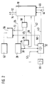
- FIG. 2 shows the integration of a device checking the voltage applied to the control unit into a part of the circuit according to FIG. 1 and FIG. 3 an embodiment of this device.
- FIG. 3 An exemplary embodiment of the safety circuit is shown in FIG.
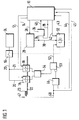
- FIG. 1 shows a control unit 10 which is connected to solenoid valves 16, 18 via lines 12, 14 and which in turn is connected to a current / voltage supply 24 via lines 20, 21.
- the solenoid valves 16, 18 act on a gas supply line 22 which leads to a burner 23 and are connected in series with one another.
- a line 26 also goes from the control unit 10 to a device 28 which checks the control unit 10, hereinafter referred to as the watchdog, the output of which is connected to a safety circuit 32 via a line 30.
- Watchdogs are generally known and check periodic events within a given time window, e.g. B. the periodicity of trigger pulses.
- a line 34 branches off from line 30 and leads to a first input of an AND gate 36.
- the second input is connected to the control unit 10 via a line 38 and the output is returned to the control unit 10 via a line 40.
- the control unit 10 is connected to the safety circuit 32 via lines 42, 43.
- Test device 46 for the flame monitoring device 47 is also connected to the controller 10.
- the test device 46 is implemented by a simple AND gate. However, structures with a more complex structure that process a larger amount of data are also conceivable.
- a line 48, which leads from the flame monitoring device 47, is connected to the line 45.
- the output of the AND gate 46 is negated to an input of a further AND gate 50, the output of which is connected to the safety circuit 32 via a line 52.
- the second input of this AND gate 50 is connected to the output of a valve checking device 54 in the form of an OR gate and its inputs to the solenoid valves 16 and 18.
- the safety circuit 32 is mechanically connected to a switch 55, which makes it possible to interrupt the line 20.
- FIG. 2 shows how a device 56 checking the voltage applied to the control unit 10 is installed in the circuit arrangement according to FIG. 1 (only shown in part).
- the line 40 is led from the AND gate 36 to a first input of an OR gate 58, the output of which is connected to the control unit 10.
- the output 72 of the device 56 is connected to the second input.
- a line 60 leads from the safety circuit 32 to the device 56, for which a current / voltage supply 62 is also provided.
- FIG. 3 An embodiment of the device 56 as an undervoltage detector is shown in FIG. 3, the core of which is a comparator 64, which has a positive input with a reference voltage source 66 and a negative input via a line 67, a diode 68 and a line 60 with the line 20 connected is.
- the line 67 is also connected to the center tap of a voltage divider 70, 71 and this to the power supply 62.
- the output 72 of the comparator leads to the OR gate 58.
- FIG. 4 An exemplary embodiment of the safety circuit 32 as a bimetal control is shown in FIG. 4.
- the line 20 leads via the switch 55 to a coil 77, the output of which is connected via a line 74 to the collector of a transistor 76.
- the emitter of transistor 76 is connected to ground.
- Parallel to the collector-emitter path is a voltage divider 78, 79, at the center tap of which line 43 branches off.
- Lines 30, 42, 52 lead in parallel via diodes 80 to the base of transistor 76.
- the solenoid valves 16, 18 are closed and there is no flame. If a heat request occurs, the control unit 10 first opens one of the solenoid valves 16, 18. This leads to an energization of the safety circuit 32 via the OR gate 54 and the AND gate 50. This energization of the control unit 10 is indicated via line 43 . If there is no current supply, this control path must be defective, the control unit closes the valve again and in turn energizes the safety circuit 32 via line 42.
- the control unit 10 When functioning correctly, the control unit 10 opens the second of the valves 16, 18 and triggers the ignition. If the flame monitor 47 delivers a valid signal after the ignition via line 48, this leads via the AND gate 46 to the negated input of the AND gate 50. This prevents an output signal at 50, the energization of the safety circuit 32 is terminated and the heating is operating. If no flame signal appears within a safety time of approximately 10 seconds, the control unit 10 closes the solenoid valves 16, 18 and maintains the current supply to the safety circuit 32 until the switch 55 trips. A time of approximately 25 seconds usually elapses between the energization of the bimetal control 32 and the triggering of the switch 55.
- the watchdog 28 is tested at constant time intervals (approx. 40 sec in the exemplary embodiment) by controlled false triggering.
- the tests are carried out alternately with the trigger pulse period being too short and too long.
- the control unit 10 "blocks" the AND gate 36 and thus prevents the watchdog 28 from bringing the control unit into a defined state during the check via the lines 34, 40.
- the control unit 10 is thus able to check via the line 43 whether the watchdog 28 is energizing the safety circuit 32.
- the test duration is shorter than the response time of the switch 55, so that it does not switch when the test is running correctly.
- the AND gate 36 is "released" again.
- the watchdog 28 Since the watchdog 28 is already energizing the safety circuit 32 during the test, the blocked AND gate 36 does not impair safety, even if an error should occur in the control unit 10 during test operation. In this case, the false triggering continues for the time of the test, and the watchdog maintains the current on the safety circuit 32 until the switch 55 trips.
- self-tests of the control unit 10 can be provided such that the control unit 10 changes itself to a defined state when errors occur and causes the safety circuit 32 to be energized via the line 42.
- a first test to ensure that the safety circuit 32 was free from faults by means of a signal via line 52 was already carried out when the firing system was started.
- a second test is also carried out at constant time intervals when the burner is switched on.
- the control unit 10 "blocks" the AND gate 46 via the line 44 and thus simulates the failure of a flame detection signal.
- the output signal of the AND gate 46 goes out, which leads to an input signal at the AND gate 50 via the negation. Since the solenoid valves 16, 18 are energized, the OR gate 54 also supplies a signal to the AND gate 50, which creates a signal on line 52.
- the energization of the safety circuit 32 is in turn recognized by the control unit 10 via the line 43.
- the effective flame detection signal on line 48 is tapped off by line 45 and passed directly to control unit 10.
- the device 56 which is constructed in the form of an undervoltage detector, monitors the supply voltage of the control unit 10 in such a way that an output signal is sent to the control unit 10 when a certain threshold value is undershot, thereby converting it into a defined state.
- This output signal is advantageously connected to the output signal of the AND gate 36 via an OR gate 58.
- the same input on the control unit 10 can be used as is also available to the watchdog circuit 28, 34, 36, 40.
- a connection between the safety circuit 32 and the undervoltage detector 56 makes it possible to keep the control unit 10 in a defined state via the undervoltage detector 56 when the switch 55 is triggered.
- the comparator 64 compares a reference voltage 66 with a partial voltage across the voltage divider 70, 71, which is derived from the current / voltage supply 62. As long as this partial voltage is greater than the reference voltage 66, there is no signal at the output 72. If the supply voltage 62 drops, the partial voltage drops above 71 and generates an output signal.
- the influence of the safety circuit 32 on the undervoltage detector 56 can take place by a connection via a diode 68 between the center tap of the voltage divider 70, 71 and the line 20.
- switch 55 When switch 55 is closed, the second (higher) supply voltage of the current / voltage supply 24 has no influence on the comparator 64 because of the diode 68.
- the diode 68 is operated in the forward direction, as a result of which the voltage at the voltage divider 70, 71 drops and causes an output signal at output 72.
- the circuitry implementation of the exemplary embodiments is possible in different ways.
- the control unit is preferably implemented as a microcomputer. A discrete structure can also be provided in simpler devices.
- the logical elements can be implemented as discrete components, for example with AND and OR operations.
- An integrated solution that includes all functions is particularly suitable.
- implementation in relay technology can also be advantageous.
Landscapes
- Engineering & Computer Science (AREA)
- Chemical & Material Sciences (AREA)
- Combustion & Propulsion (AREA)
- Mechanical Engineering (AREA)
- General Engineering & Computer Science (AREA)
- Regulation And Control Of Combustion (AREA)
Applications Claiming Priority (2)
| Application Number | Priority Date | Filing Date | Title |
|---|---|---|---|
| DE4111947 | 1991-04-12 | ||
| DE4111947A DE4111947A1 (de) | 1991-04-12 | 1991-04-12 | Schaltungsanordnung und verfahren zum ueberwachen eines brennstoffbeheizten geraetes |
Publications (3)
| Publication Number | Publication Date |
|---|---|
| EP0508081A2 true EP0508081A2 (fr) | 1992-10-14 |
| EP0508081A3 EP0508081A3 (en) | 1993-02-03 |
| EP0508081B1 EP0508081B1 (fr) | 1996-09-25 |
Family
ID=6429439
Family Applications (1)
| Application Number | Title | Priority Date | Filing Date |
|---|---|---|---|
| EP92103323A Expired - Lifetime EP0508081B1 (fr) | 1991-04-12 | 1992-02-27 | Circuit et procédé pour surveiller un appareil chauffé au combustible |
Country Status (3)
| Country | Link |
|---|---|
| EP (1) | EP0508081B1 (fr) |
| DE (2) | DE4111947A1 (fr) |
| ES (1) | ES2093126T3 (fr) |
Cited By (4)
| Publication number | Priority date | Publication date | Assignee | Title |
|---|---|---|---|---|
| WO2002077530A1 (fr) * | 2001-03-26 | 2002-10-03 | Sit La Precisa S.P.A. | Dispositif de controle et de securite pour systeme de valve |
| EP1070919A3 (fr) * | 1999-07-23 | 2002-12-18 | FAGOR, S.Coop | Circuit de commande pour brûleurs à gaz |
| EP1103765A3 (fr) * | 1999-11-24 | 2003-09-17 | Honeywell B.V. | Dispositif de surveillance de la température de l'eau |
| EP2295863A3 (fr) * | 2009-08-06 | 2014-06-11 | Robert Bosch GmbH | Système de combustion, automate de chauffage au gaz ainsi que dispositif et procédé d'arrêt d'une amenée de combustible correspondant |
Families Citing this family (1)
| Publication number | Priority date | Publication date | Assignee | Title |
|---|---|---|---|---|
| DE19616065A1 (de) * | 1996-04-23 | 1997-11-06 | Bosch Gmbh Robert | Schaltungsanordnung zum Überwachen eines brennstoffbeheizten Gerätes |
Family Cites Families (7)
| Publication number | Priority date | Publication date | Assignee | Title |
|---|---|---|---|---|
| US4211526A (en) * | 1978-11-06 | 1980-07-08 | Honeywell Inc. | Control system for redundant valves |
| US4518345A (en) * | 1983-02-28 | 1985-05-21 | Emerson Electric Co. | Direct ignition gas burner control system |
| US4695246A (en) * | 1984-08-30 | 1987-09-22 | Lennox Industries, Inc. | Ignition control system for a gas appliance |
| FR2600437B1 (fr) * | 1986-06-18 | 1993-12-31 | Telemecanique Electrique | Procede et dispositif pour la commande redondante d'un organe de puissance |
| US4832594A (en) * | 1987-09-10 | 1989-05-23 | Hamilton Standard Controls, Inc. | Control system with timer redundancy |
| US4842510A (en) * | 1987-09-10 | 1989-06-27 | Hamilton Standard Controls, Inc. | Integrated furnace control having ignition and pressure switch diagnostics |
| US4854852A (en) * | 1987-09-21 | 1989-08-08 | Honeywell Inc. | System for redundantly processing a flame amplifier output signal |
-
1991
- 1991-04-12 DE DE4111947A patent/DE4111947A1/de not_active Withdrawn
-
1992
- 1992-02-27 ES ES92103323T patent/ES2093126T3/es not_active Expired - Lifetime
- 1992-02-27 DE DE59207215T patent/DE59207215D1/de not_active Expired - Fee Related
- 1992-02-27 EP EP92103323A patent/EP0508081B1/fr not_active Expired - Lifetime
Cited By (5)
| Publication number | Priority date | Publication date | Assignee | Title |
|---|---|---|---|---|
| EP1070919A3 (fr) * | 1999-07-23 | 2002-12-18 | FAGOR, S.Coop | Circuit de commande pour brûleurs à gaz |
| EP1103765A3 (fr) * | 1999-11-24 | 2003-09-17 | Honeywell B.V. | Dispositif de surveillance de la température de l'eau |
| WO2002077530A1 (fr) * | 2001-03-26 | 2002-10-03 | Sit La Precisa S.P.A. | Dispositif de controle et de securite pour systeme de valve |
| EP2295863A3 (fr) * | 2009-08-06 | 2014-06-11 | Robert Bosch GmbH | Système de combustion, automate de chauffage au gaz ainsi que dispositif et procédé d'arrêt d'une amenée de combustible correspondant |
| EP2295863B1 (fr) | 2009-08-06 | 2019-05-01 | Robert Bosch GmbH | Système de combustion, automate de chauffage au gaz ainsi que dispositif et procédé d'arrêt d'une amenée de combustible correspondant |
Also Published As
| Publication number | Publication date |
|---|---|
| DE59207215D1 (de) | 1996-10-31 |
| EP0508081B1 (fr) | 1996-09-25 |
| DE4111947A1 (de) | 1992-10-15 |
| ES2093126T3 (es) | 1996-12-16 |
| EP0508081A3 (en) | 1993-02-03 |
Similar Documents
| Publication | Publication Date | Title |
|---|---|---|
| DE3731142C2 (de) | Überwachungseinrichtung in einer elektronischen Steuereinheit | |
| EP0577641B1 (fr) | Circuit pour regulateur | |
| DE2109226C3 (de) | Schaltungsanordnung zur Überwachung der Funktion des Flammenfühlers | |
| WO1995015517A1 (fr) | Commande et regulation d'une porte entrainee par un moteur electromecanique | |
| DE4441070C2 (de) | Sicherheitsschalteranordnung | |
| DE4101598A1 (de) | Schaltungsanordnung fuer eine blockiergeschuetzte bremsanlage | |
| DE2643492C2 (de) | Blockiergeschützte Fahrzeugbremsanlage | |
| DE3508608C2 (fr) | ||
| DE4242792C2 (de) | Sicherheitsschalteranordnung | |
| CH650087A5 (de) | Relais-steueranordnung. | |
| EP0007579A1 (fr) | Circuit de surveillance de l'état de systèmes de signalisation, spécialement de systèmes lumineux de signalisation de circulation routière | |
| EP0676055B1 (fr) | Agencement de circuits permettant de surveiller une pluralite de bobines | |
| EP0326694A1 (fr) | Système de sécurité pour moteur à combustion interne | |
| DE3926377C2 (de) | Elektronisches Steuergerät für eine Brennkraftmaschine | |
| EP0508081B1 (fr) | Circuit et procédé pour surveiller un appareil chauffé au combustible | |
| DE19828057A1 (de) | Vorrichtung und Verfahren zur Überwachung der Spannungsversorgung einer Kfz-Steuergerätanordnung | |
| DE3101747C2 (fr) | ||
| DE3728561A1 (de) | Verfahren zur ueberpruefung einer ueberwachungseinrichtung fuer einen mikroprozessor | |
| DE10011410A1 (de) | Vorrichtung zur sicheren Signalerzeugung | |
| DE2630234A1 (de) | Schutzsystem mit pruefmoeglichkeit | |
| EP0660043A1 (fr) | Dispositif de commande pour commander des appareils de commutation selon un programme de temps | |
| EP0596297B1 (fr) | Méthode et dispositif pour tester une unité de surveillance de système de commande de moteur | |
| DE2222258B1 (de) | Steuerschaltung fuer eine brenneranlage | |
| DE10127056A1 (de) | Vorrichtung zur sicheren Signalerzeugung | |
| DE102004020538B4 (de) | Elektronische Steuereinrichtung und Verfahren zur Steuerung des Betriebs von Kraftfahrzeugkomponenten |
Legal Events
| Date | Code | Title | Description |
|---|---|---|---|
| PUAI | Public reference made under article 153(3) epc to a published international application that has entered the european phase |
Free format text: ORIGINAL CODE: 0009012 |
|
| AK | Designated contracting states |
Kind code of ref document: A2 Designated state(s): DE ES FR GB IT |
|
| PUAL | Search report despatched |
Free format text: ORIGINAL CODE: 0009013 |
|
| AK | Designated contracting states |
Kind code of ref document: A3 Designated state(s): DE ES FR GB IT |
|
| 17P | Request for examination filed |
Effective date: 19930708 |
|
| 17Q | First examination report despatched |
Effective date: 19950214 |
|
| GRAG | Despatch of communication of intention to grant |
Free format text: ORIGINAL CODE: EPIDOS AGRA |
|
| GRAH | Despatch of communication of intention to grant a patent |
Free format text: ORIGINAL CODE: EPIDOS IGRA |
|
| GRAH | Despatch of communication of intention to grant a patent |
Free format text: ORIGINAL CODE: EPIDOS IGRA |
|
| GRAA | (expected) grant |
Free format text: ORIGINAL CODE: 0009210 |
|
| AK | Designated contracting states |
Kind code of ref document: B1 Designated state(s): DE ES FR GB IT |
|
| REF | Corresponds to: |
Ref document number: 59207215 Country of ref document: DE Date of ref document: 19961031 |
|
| ET | Fr: translation filed | ||
| ITF | It: translation for a ep patent filed | ||
| REG | Reference to a national code |
Ref country code: ES Ref legal event code: FG2A Ref document number: 2093126 Country of ref document: ES Kind code of ref document: T3 |
|
| GBT | Gb: translation of ep patent filed (gb section 77(6)(a)/1977) |
Effective date: 19961205 |
|
| PLBE | No opposition filed within time limit |
Free format text: ORIGINAL CODE: 0009261 |
|
| STAA | Information on the status of an ep patent application or granted ep patent |
Free format text: STATUS: NO OPPOSITION FILED WITHIN TIME LIMIT |
|
| 26N | No opposition filed | ||
| PGFP | Annual fee paid to national office [announced via postgrant information from national office to epo] |
Ref country code: ES Payment date: 19990208 Year of fee payment: 8 |
|
| PGFP | Annual fee paid to national office [announced via postgrant information from national office to epo] |
Ref country code: FR Payment date: 19990219 Year of fee payment: 8 |
|
| PGFP | Annual fee paid to national office [announced via postgrant information from national office to epo] |
Ref country code: GB Payment date: 19990225 Year of fee payment: 8 |
|
| PGFP | Annual fee paid to national office [announced via postgrant information from national office to epo] |
Ref country code: DE Payment date: 19990511 Year of fee payment: 8 |
|
| PG25 | Lapsed in a contracting state [announced via postgrant information from national office to epo] |
Ref country code: GB Free format text: LAPSE BECAUSE OF NON-PAYMENT OF DUE FEES Effective date: 20000227 |
|
| PG25 | Lapsed in a contracting state [announced via postgrant information from national office to epo] |
Ref country code: ES Free format text: LAPSE BECAUSE OF NON-PAYMENT OF DUE FEES Effective date: 20000228 |
|
| GBPC | Gb: european patent ceased through non-payment of renewal fee |
Effective date: 20000227 |
|
| PG25 | Lapsed in a contracting state [announced via postgrant information from national office to epo] |
Ref country code: FR Free format text: LAPSE BECAUSE OF NON-PAYMENT OF DUE FEES Effective date: 20001031 |
|
| PG25 | Lapsed in a contracting state [announced via postgrant information from national office to epo] |
Ref country code: DE Free format text: LAPSE BECAUSE OF NON-PAYMENT OF DUE FEES Effective date: 20001201 |
|
| REG | Reference to a national code |
Ref country code: FR Ref legal event code: ST |
|
| REG | Reference to a national code |
Ref country code: ES Ref legal event code: FD2A Effective date: 20011010 |
|
| PG25 | Lapsed in a contracting state [announced via postgrant information from national office to epo] |
Ref country code: IT Free format text: LAPSE BECAUSE OF NON-PAYMENT OF DUE FEES Effective date: 20050227 |